Avidyne Entegra EX5000 Pilot's Manual
Multi-function display for piper pa34, pa46 seneca v, meridian, mirage
Hide thumbs
Also See for Entegra EX5000:
- Pilot's manual (190 pages) ,
- Installation manual (114 pages) ,
- Field level troubleshooting reference manual (39 pages)
Table of Contents
Advertisement
Quick Links
Advertisement
Table of Contents

Related Manuals for Avidyne Entegra EX5000


Summary of Contents for Avidyne Entegra EX5000
- Page 1 600-00121-001 Rev 01 Entegra EX5000...
- Page 2 Entegra EX5000 600-00121-001 Rev 01...
- Page 3 Software Part Number 530-00235-000 Release 8.2.2 or Later Hardware Part Number 700-00030-() System Configuration When contacting your dealer or Avidyne technical support, and when logging onto MyAvidyne.com for the first time, please have your EX5000 serial number and Subscriber Communicator (SC) serial...
- Page 4 Note: All images contained within this document, including screenshots and other displays, are for reference use only and are subject to change. The images contained herein may differ slightly from your actual equipment or display. Entegra EX5000 -ii- 600-00121-001 Rev 01...
- Page 5 Notes and Warnings Notes and warnings provide guidance for the use of the EX5000. Avidyne strongly suggests that you pay close attention to notes and warnings for your own safety. For example: Note: Notes provide useful information about how to use the EX5000.
- Page 6 By using Broadcast datalink, you can access weather information made available from sources external to Avidyne Corporation. Avidyne does not control, edit or review the content of such information and is not responsible for such information or the actions or conduct of any company that provides sources of weather data through the Broadcast datalink.
- Page 7 The NOTAM information provided by the EX5000 is for planning purposes only. Always consult official NOTAMS for the latest restrictions. Avidyne does not provide a complete list of NOTAMS. Local NOTAMS, most laser light NOTAMS, and any NOTAMS other than restricted airspace are not listed.
- Page 8 This page intentionally left blank. Entegra EX5000 -vi- 600-00121-001 Rev 01...
-
Page 9: Table Of Contents
Table of Contents 1 Introduction .............. 1 Using the Entegra EX5000 MFD ..........2 Power Up..................4 2 Map Page ..............7 Map Page—Controls ..............8 Map Symbols—Terrain and Position ......... 16 Map Symbols—Runways and Flight Plan ......... 20 Map Orientation Control ............22 Errors Displayed on the Map Page.......... - Page 10 Overview of Datalink Weather ..........126 Symbols Displayed using Datalink .......... 128 Using Datalink without a Traffic Sensor or Radar ..... 130 Nearest Page with Datalink Weather........131 Trip Page with Datalink Weather ..........132 600-00121-001 Rev 01 -viii- Entegra EX5000...
- Page 11 Radar Messages ..............169 Avionics Abbreviations ............171 13 Using EX5000 Outside the US ......175 Features Available in the US Only........... 175 Features Available in North America ........175 Features Specific to International Flight ........175 600-00121-001 Rev 01 -ix- Entegra EX5000...
- Page 12 List of Figures Figure 1.1 Entegra EX5000 MFD............2 Figure 1.2 Meridian Startup Page ............4 Figure 2.1 Map Page Controls ............8 Figure 2.2 TWXCELL Mode Display ..........13 Figure 2.3 Map Page Symbols–Terrain and Position ...... 16 Figure 2.4 Map page Symbols—Runways and Flight Plan....20 Figure 3.1 Map Page—Traffic Mode ..........
- Page 13 Figure 11.2 Graphical METAR Symbols ........126 Figure 11.3 Broadcast Datalink Weather ........128 Figure 11.4 Datalink Weather without Traffic Sensors....130 Figure 11.5 Nearest Page with Broadcast Datalink ....... 131 Figure 11.6 Trip Page with Datalink Weather ........ 132 600-00121-001 Rev 01 -xi- Entegra EX5000...
- Page 14 Table 12.18 Mirage Engine Messages ......... 163 Table 12.19 PFD Messages ............164 Table 12.20 Broadcast Datalink Messages ........165 Table 12.21 Radar Messages and Colors ........169 Table 12.22 Avionics Abbreviations ..........171 600-00121-001 Rev 01 -xii- Entegra EX5000...
-
Page 15: Introduction
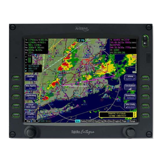
Introduction The Entegra EX5000 Multi-Function Display (MFD) provides a moving map view of your flight plan, on-board radar data, broadcast datalink weather, lightning, traffic, navigation data, obstacles, terrain, and CMax™ approach plates with an intuitive user interface. The EX5000 offers the following standard and optional features: Engine instruments display. -
Page 16: Using The Entegra Ex5000 Mfd
Introduction 1.1 Using the Entegra EX5000 MFD The controls on the bezel of the Entegra EX5000 are placed to allow you quick and intuitive access to the information you need, when you need it (see Figure 1.1). Figure 1.1 Entegra EX5000 MFD 1) PhotoCell Light Sensor—Automatically compensates display... - Page 17 Using the Entegra EX5000 MFD 3) Data Port—Provides a front panel access point for loading database updates. Note: When removing the rubber cap from the data port, pull the cap gently from the top until it pops out. Make sure the cap is out of the way (but not removed) before plugging anything into the USB port.
-
Page 18: Power Up
If the issue date for the next update has passed, the Startup page displays “Update Available” in white. If the current date is more than a week past the issue of the next update, “Update Required” displays in yellow cautionary text. Entegra EX5000 600-00121-001 Rev 01... - Page 19 For NavData, the date range displays if the data is valid; if it is not valid, the word “EXPIRED” and the expiration data display in yellow. For more information about updating CMax and NavData, see Section 12.1, "Updating Your Databases" on page 134. 600-00121-001 Rev 01 Entegra EX5000...
- Page 20 Introduction THIS PAGE INTENTIONALLY LEFT BLANK. Entegra EX5000 600-00121-001 Rev 01...
-
Page 21: Map Page
This section discusses the following topics: Map Page—Controls, page 8 Map Symbols—Terrain and Position, page 16 Map Symbols—Runways and Flight Plan, page 20 Map Orientation Control, page 22 Errors Displayed on the Map Page, page 22 600-00121-001 Rev 01 Entegra EX5000... -
Page 22: Map Page-Controls
Radar—Cycles through the available on-board Radar functions. These do not affect the Datalink settings. For more information, see Section 4.1, "Radar—Map Page Overlay" on page 31. On—Places the radar in normal operation. Test—Initiates radar self-test function. Entegra EX5000 600-00121-001 Rev 01... - Page 23 25NM accurately display lightning strikes outside the 25 NM radius. Datalink - Displays lightning strikes obtained from the Datalink weather service, depending on the weather service and subscription level. Lightning strikes are 600-00121-001 Rev 01 Entegra EX5000...
- Page 24 View—Orients the map for either Track/Heading Up or North Up. FORWARD and CENTER views are oriented with Track/ Heading Up. North Up orients the map to true North, with the ownship symbol rotated to show track/heading. Entegra EX5000 -10- 600-00121-001 Rev 01...
- Page 25 Both systems provide datalink radar data—a composite image depicting precipitation as seen by multiple ground-based weather radar sites. The image is color-coded to show intensity levels and precipitation types. Broadcast Datalink, however, especially at a 600-00121-001 Rev 01 -11- Entegra EX5000...
- Page 26 The TWX670 detects and measures lightning strike energy and generates cell data that the EX5000 displays in color. This mode shows dangerous convective areas that you must avoid. Entegra EX5000 -12- 600-00121-001 Rev 01...
-
Page 27: Figure 2.2 Twxcell Mode Display
Table 2.1Thunderstorm Activity (Cell) Colors Color Interpretation Intense thunderstorm activity - presence of hazardous atmospheric conditions is certain. Orange Weather conditions are approaching intense thunderstorm activity. Orange- Heavy thunderstorm activity - high likelihood of Yellow hazardous atmospheric conditions. 600-00121-001 Rev 01 -13- Entegra EX5000... - Page 28 1, 2, 5, 10, 15, 20, 30, 40, 50, 75, 100, 150, 200, 300, 400, 500, 750, 1000, and 1500. Note: The terrain base map is automatically removed and Nav database information is fully decluttered at 750NM and higher ranges. Entegra EX5000 -14- 600-00121-001 Rev 01...
- Page 29 • The word “FAIL” displays in the sensor's status line in yellow. • The sensor symbol changes from cyan to yellow (if the sensor was on). What to do: • Select the Setup page and perform Self-Test for the applicable sensor. 600-00121-001 Rev 01 -15- Entegra EX5000...
-
Page 30: Map Symbols-Terrain And Position
The H/T Block provides digital readout of the current heading, or actual track. Map orientation is indicated in the triangle to the right of the H/T Block. Entegra EX5000 -16- 600-00121-001 Rev 01... -
Page 31: Table 2.2 Track Indicator Graphics
5) Lightning and Storm Cell Indications - Displays geographically referenced lightning strikes (if configured). Strikes are displayed using a yellow X ( ) in Strike Mode and by a yellow + ( ) in 600-00121-001 Rev 01 -17- Entegra EX5000... - Page 32 The displayed terrain and obstacle indicators are only advisory. It is dangerous to rely on the EX5000 as the sole source of obstacle and terrain avoidance information. Always refer to current aeronautical charts for appropriate terrain and obstacle information. Entegra EX5000 -18- 600-00121-001 Rev 01...
- Page 33 Flight Service. 9) Compass Rose/Range Ring—Displays a 360-degree or 120- degree compass circle or arc and also indicates current range setting. The range number is the distance from the airplane symbol to the compass arc. 600-00121-001 Rev 01 -19- Entegra EX5000...
-
Page 34: Map Symbols-Runways And Flight Plan
Note: For most GPS units, the EX5000 cannot display the active course leg when you are adjusting the desired track in OBS mode. The desired track leg will be displayed after you finish selecting the course and exit the OBS mode of the GPS. Entegra EX5000 -20- 600-00121-001 Rev 01... -
Page 35: Table 2.3 Obstacle Graphics
Note: For example, a 2000 foot tall TV tower located in Denver (elevation 5300 feet MSL) will be depicted as being at 7300 feet MSL. Table 2.3 Obstacle Graphics Graphic Meaning Height (AGL) Single Obstacle 200’ AGL to < 1000’ AGL 600-00121-001 Rev 01 -21- Entegra EX5000... -
Page 36: Map Orientation Control
If the primary GPS fails during flight and you have a second GPS connected to the EX5000, you may switch your GPS input to the backup source by pressing the Nav Src button on the Aux page. Entegra EX5000 -22- 600-00121-001 Rev 01... -
Page 37: Loss Of Heading Input
A problem with heading from a Primary Flight Display (PFD). The GPS (This would be a pass through of the heading from another source, such as an Avidyne PFD. The GPS does not determine heading). If an installed heading source becomes unavailable or invalid, the EX5000 will automatically switch to using GPS track for map alignment. - Page 38 Map Page Entegra EX5000 -24- 600-00121-001 Rev 01...
-
Page 39: Traffic Mode And The Traffic Page
The Traffic page is a specially configured Map page with the following settings: View—Center, with heading (or track) up Range—5 NM Base Map—No terrain or political boundaries Declutter—No symbol or airspace depictions Lightning—Not displayed Flight Plan—Displayed 600-00121-001 Rev 01 -25- Entegra EX5000... -
Page 40: Figure 3.1 Map Page-Traffic Mode
Pilot Guide. For TIS sensors, see Section 1-3-5 of the Aeronautical Information Manual. The available Traffic button modes are listed below. For more information on specific traffic sensor modes, consult the user documentation for your traffic sensor. Entegra EX5000 -26- 600-00121-001 Rev 01... - Page 41 OFF. Note that some TCAD installations will support automatic mode switching by the TCAD unit. The current mode is always reported on the EX5000 screen. All other 735 Connected Devices—Traffic modes are ABOVE, NORMAL, UNLIMTD, BELOW, and DSPLY OFF. 600-00121-001 Rev 01 -27- Entegra EX5000...
-
Page 42: Traffic Symbols
1) Relative bearing of target. 2) Range in nautical miles. 3) Relative altitude of traffic to your current aircraft altitude. For example, -200 would be 200 feet below your aircraft, as reported by the traffic sensor. Entegra EX5000 -28- 600-00121-001 Rev 01... -
Page 43: Tis Sensor Status
TIS data is not available at the current aircraft location. SBY—The TIS sensor is in standby mode. DATA FAIL—The TIS sensor has reported an internal fault. Traffic information will be removed from display. 600-00121-001 Rev 01 -29- Entegra EX5000... - Page 44 Traffic Mode and the Traffic Page THIS PAGE INTENTIONALLY LEFT BLANK. Entegra EX5000 -30- 600-00121-001 Rev 01...
-
Page 45: Radar Page
Radar Page The Entegra EX5000 radar display replaces a separate indicator and provides a more intuitive user interface that is integrated with the other sensors such as traffic and lightning (if installed). To view the Radar page, select Radar from the Page Bar. - Page 46 Note: For Radar messages, see Table 12.21 Radar Messages and Colors on page 169. Radar is intended as a severe weather avoidance tool only. Do not use the EX5000 data to penetrate severe weather, thunderstorms, cells or lines of cells. Entegra EX5000 -32- 600-00121-001 Rev 01...
- Page 47 For example, if a second button is available for Radar functions, a dedicated Radar Off button becomes available.Similarly, if other buttons become free, additional Radar buttons display, including Radar Off, Radar On, Radar Standby, and Radar Test. 600-00121-001 Rev 01 -33- Entegra EX5000...
-
Page 48: Dedicated Radar Page
3) Tilt Control—The left inner knob controls the antenna tilt. Each click of the knob changes the tilt by 0.25°. Turning the knob to the Entegra EX5000 -34- 600-00121-001 Rev 01... - Page 49 ART-2000: 10, 20, 40, 80, 160, and 240NM. ART-2100: 5, 10, 20, 40, 80, 160, 240, and 320NM. Turn the knob clockwise to increase the range scale and counter clockwise to decrease the scale. 600-00121-001 Rev 01 -35- Entegra EX5000...
- Page 50 Radar Page Based on recommendations made by the FAA and the radar manufacturer, Avidyne recommends the following safety procedures: • At startup, if the radar is not being used in flight, ensure that it is turned off. • At startup, if the radar is being used during the flight, switch to standby as soon as possible.
-
Page 51: Dedicated Radar In Ground Mode
EX5000. When the radar is in standby, you will not see the moving scan indicator, or radar echo returns, and the screen annunciation says “STBY”. In Standby mode, the antenna is moved to in the desired park position. 600-00121-001 Rev 01 -37- Entegra EX5000... - Page 52 (Items 5, 6, 7 & 8) to control the “Settings” as described on page 30 and 31. Pushing the Control button again brings the top right three button functions back to “Mode” as described above. Entegra EX5000 -38- 600-00121-001 Rev 01...
-
Page 53: Using An Art-2000 Or Art-2100 Radar
Collins - Target Alert consists of two screen indications. When Target Alert is ON but not active, the alert is displayed as, “TGT”, in white text in the upper right corner of the screen. 600-00121-001 Rev 01 -39- Entegra EX5000... - Page 54 A vertical profile annunciation (PROFILE) provides the current azimuth displayed on the screen, in degrees left (L), right (R) or centered. Entegra EX5000 -40- 600-00121-001 Rev 01...
-
Page 55: Figure 4.5 Vertical Profile View
Using an ART-2000 or ART-2100 Radar Figure 4.5 Vertical Profile View 600-00121-001 Rev 01 -41- Entegra EX5000... -
Page 56: Radar Warnings
EX5000. The MPEL boundary shown below does not guarantee protection against ignition of flammable materials or damage to sensitive electronic equipment exposed to microwave energy from your radar. Figure 4.6 Maximum Permissible Exposure Level Entegra EX5000 -42- 600-00121-001 Rev 01... -
Page 57: Taws Page (Optional)
TAWS-B installation, and is intended only to enhance situational awareness. All terrain avoidance maneuvering must be predicated on indications from the installed TAWS system, and not from the EX5000. TAWS Information Figure 5.1 TAWS Information 600-00121-001 Rev 01 -43- Entegra EX5000... - Page 58 The elevation value colors are not modified in this case, but continue to correspond to the colors that would appear in the TAWS display under normal circumstances, and represent the actual elevation of the terrain relative to the aircraft. Entegra EX5000 -44- 600-00121-001 Rev 01...
- Page 59 “TAWS Failed”, but will resume normal operation within a few seconds. Note: The EX5000 displays TAWS data that is received from the TAWS sensor. The EX5000 does not generate its own TAWS data. 600-00121-001 Rev 01 -45- Entegra EX5000...
- Page 60 100 feet or more, is not to be used for navigation. It is presented to provide the crew with additional situational awareness of true height above sea level upon which TAWS terrain alerting and display is based. Entegra EX5000 -46- 600-00121-001 Rev 01...
-
Page 61: Taws Operation
When a caution alert is triggered, the terrain or obstacle that caused the alert displays in bright yellow, as shown below. In addition, a message describing the nature of the alert is presented in the message bar. Figure 5.2 Terrain Caution Condition 600-00121-001 Rev 01 -47- Entegra EX5000... -
Page 62: Figure 5.3 Terrain Warning Condition
EX5000 automatically switches to the TAWS Display page. The message bar is removed from the display when the EGPWS is no longer in alert status, or if you acknowledge the message from the TAWS page. Entegra EX5000 -48- 600-00121-001 Rev 01... -
Page 63: Taws Reference
EGPWS, the system may still be initializing and the TAWS page will display the text “TAWS Initializing” rather than the expected terrain. The EGPWS and TAWS page will begin normal operation when initialization is complete. 600-00121-001 Rev 01 -49- Entegra EX5000... -
Page 64: Table 5.1 Egpws Display Color Formats
Black No significant terrain/obstacle. 16% Blue Peaks mode only. Water at sea level elevation (0 feet MSL). Magenta Unknown terrain. No terrain data in the data base for the Dots magenta area shown. Entegra EX5000 -50- 600-00121-001 Rev 01... -
Page 65: Cmax Chart Pages (Optional)
CMax Chart Pages (Optional) CMax™ is an optional Avidyne feature that allows you to view Jeppesen Terminal Procedure charts on your EX5000. If CMax is installed on your aircraft, you can select Charts from the Page Bar to view the CMax charts. This section discusses the following topics:... - Page 66 CMax Chart Pages (Optional) Entegra EX5000 -52- 600-00121-001 Rev 01...
-
Page 67: European Vfr Charts
CMax Selection Page below European VFR charts. If a VFR chart is selected pressing "Display Airport" will display the VFR airport diagram. Likewise, if an IFR chart is selected, pressing "Display Airport" will display the standard Jeppesen airport diagram. 600-00121-001 Rev 01 -53- Entegra EX5000... -
Page 68: About Cmax
Jeppesen printed charts. CMax requires that you have a valid chart data subscription from Jeppesen Sanderson, Inc. For information on obtaining a CMax subscription, see the Avidyne Data Update Guide or the Jeppesen website at www.jeppesen.com. The Data Update Guide also contains instructions for loading the chart data to your Zip Drive or USB Flash Memory Drive. -
Page 69: About Geo-Referenced Charts
On landing, if the Chart page is being displayed, the EX5000 will automatically switch to display the Airport diagram for the current location when the GPS Ground Speed drops below 50 knots. 600-00121-001 Rev 01 -55- Entegra EX5000... -
Page 70: Figure 6.2 Cmax Airport Chart-Plan View
FPL symbol is crossed out. Note that if a chart is not geo-referenced or no flight plan is received from the GPS, the flight plan cannot be displayed even if the option is selected. Entegra EX5000 -56- 600-00121-001 Rev 01... - Page 71 If you have panned the view, using Zoom to zoom all the way out to the full-screen chart size will also re-center the chart on the page. A typical approach procedure chart is shown in Figure 6.3: 600-00121-001 Rev 01 -57- Entegra EX5000...
-
Page 72: Figure 6.3 Cmax Procedure Chart-Plan View
3) Flight Plan—The flight plan displays when the you set FlightPlan to Display (on the Selection page, page 64) and the chart is geo- referenced. If a flight plan is expected and does not appear, check that you selected the correct airport and approach. Entegra EX5000 -58- 600-00121-001 Rev 01... - Page 73 KBED to KLAX passes over KEMT. If you bring up KEMT charts, the KBED-KLAX flight plan will not display. To display the flight plan over KEMT, a waypoint on a KEMT approach must be included in the flight plan. 600-00121-001 Rev 01 -59- Entegra EX5000...
-
Page 74: Cmax Chart Views
“preview pane” of the Plan View, which, although too small to read all chart details, gives the user a general overview of the approach for situational awareness. The flight plan and ownship symbol are also displayed on the preview pane. Entegra EX5000 -60- 600-00121-001 Rev 01... -
Page 75: Figure 6.4 Procedure Chart Views
3 of 4 Profile Includes the profile view of the approach procedure. 4 of 4 Minimums Shows the descent minimums for the approach. Header View Profile View Minimums View Figure 6.4 Procedure Chart Views 600-00121-001 Rev 01 -61- Entegra EX5000... -
Page 76: Airport Chart Views
Includes general chart information and communications frequencies. 3 of 4 Runways Shows runway information for the airport. 4 of 4 Departure Displays specific departure procedure information. Header View Runways View Departure View Figure 6.5 Airport Chart Views Entegra EX5000 -62- 600-00121-001 Rev 01... -
Page 77: Figure 6.6 Airport Departure Chart (Night View)
Charts that cannot be split into smaller sections are shown as a complete chart, as shown in Figure 6.6, with the View button not displayed, since only one View type is available. Figure 6.6 Airport Departure Chart (Night View) 600-00121-001 Rev 01 -63- Entegra EX5000... -
Page 78: Cmax Selection Page
Chart NOTAMS to bring up a window that lists any associated chart NOTAMs for the airport currently entered in the Airport Entry Field. See Section 6.7.2, "Chart NOTAMs Page" on page 67 for more information. Entegra EX5000 -64- 600-00121-001 Rev 01... -
Page 79: Selecting An Airport
Chart page by pressing the Display Airport button. 6.7.1 Selecting an Airport Use the Airport Selection page to specify the airport charts and runway information you want to view. 600-00121-001 Rev 01 -65- Entegra EX5000... -
Page 80: Figure 6.8 Airport Selection Page
A list of all charts available for the identified airport appears in the chart list area. The name of the airport in the Airport Entry Field is listed next to the entry field. Entegra EX5000 -66- 600-00121-001 Rev 01... -
Page 81: Chart Notams Page
The character selection goes from A to Z, then 0 to 9, then restarts at A. 6.7.2 Chart NOTAMs Page Displays the chart NOTAMs associated with the currently displayed airport. 600-00121-001 Rev 01 -67- Entegra EX5000... -
Page 82: Figure 6.9 Chart Notams
Chart NOTAMs specific to that airport are listed first, followed by any general chart NOTAMs. Note: Chart NOTAMs address changes to information contained on the charts, and do not include local or regional operational NOTAMs. Always obtain local and regional NOTAMS before any flight. Entegra EX5000 -68- 600-00121-001 Rev 01... - Page 83 • Expected airports are not available for chart selection. If you observe any of these, reload the CMax chart data as described in the Avidyne Data Update Guide or in the Jeppesen JeppView for MFD Quick Start Guide. If problems persist, contact your dealer or Avidyne Technical Support.
- Page 84 CMax Chart Pages (Optional) THIS PAGE INTENTIONALLY LEFT BLANK. Entegra EX5000 -70- 600-00121-001 Rev 01...
-
Page 85: Trip Page
Figure 7.1 Trip Page Information with METAR Display 1) Current ground speed and track—As reported by your GPS Navigator. 2) Course Deviation Indicator (CDI)—Shows lateral distance (Crosstrack deviation) from desired course, providing continuous navigation reference when viewing the Trip page. 600-00121-001 Rev 01 -71- Entegra EX5000... - Page 86 The EX5000 adds intermediate waypoints along your flight path to provide weather information between flight plan waypoints for longer flight plan legs. This can provide you with a fuller picture of enroute conditions. Entegra EX5000 -72- 600-00121-001 Rev 01...
- Page 87 Aux Main page and in the message bar. For example, if 91 minutes has elapsed since the last TAF data was 600-00121-001 Rev 01 -73- Entegra EX5000...
- Page 88 Products: This is the standard Status page which display the product ages and receiver status Stations: This page shows information about which stations are providing data and the completeness of that data. White Entegra EX5000 -74- 600-00121-001 Rev 01...
- Page 89 (not magnetic) North. Winds are interpolated for each Trip page waypoint and are based on a computer forecast model that is updated hourly. The XM Freezing Level forecast (see figure) displays the expected altitude of the freezing level for the waypoint. 600-00121-001 Rev 01 -75- Entegra EX5000...
- Page 90 Trip page. Use the GPS as the primary source of navigation information for approach procedures. Consult your avionics installation facility to determine if your EX5000 is interfaced to the Garmin GNS- 430 via ARINC 429 or RS-232. Entegra EX5000 -76- 600-00121-001 Rev 01...
- Page 91 THIS PAGE INTENTIONALLY LEFT BLANK. 600-00121-001 Rev 01 -77- Entegra EX5000...
- Page 92 Trip Page Entegra EX5000 -78- 600-00121-001 Rev 01...
-
Page 93: Figure 8.1 Nearest Page
Datalink is enabled, the text METAR for the currently selected airport is displayed on the lower half of the Nearest page. 1) Airport details—By default, displays the following details about the airports nearest to your current location: 600-00121-001 Rev 01 -79- Entegra EX5000... - Page 94 Intersections—Identifier, bearing, and distance. Obstacles—MSL (and AGL) height, bearing, and distance. 5) FILTER—Press to see all airport types (SHOW ALL) or only the airport types as defined on the Airport Filter page (ON) (see Entegra EX5000 -80- 600-00121-001 Rev 01...
-
Page 95: Figure 8.2 Airport Information Page
CMax charts, see Chapter 6 "CMax Chart Pages (Optional).” 7) Select knob—Use the Select knob to move the cursor up or down to highlight a specific airport or other data type. Figure 8.2 Airport Information Page 600-00121-001 Rev 01 -81- Entegra EX5000... - Page 96 THIS PAGE INTENTIONALLY LEFT BLANK. Entegra EX5000 -82- 600-00121-001 Rev 01...
-
Page 97: Aux Pages - Configuring The Ex5000
Aux Main Page, page 83 Airport Filter Setup Page, page 85 Declutter Setup Page, page 87 Data Block Edit Page, page 89 System Time Page, page 91 Aux Main Page Figure 9.1 Aux Main Page 600-00121-001 Rev 01 -83- Entegra EX5000... - Page 98 Aux Pages – Configuring the EX5000 1) Entegra EX5000 Version Information—Displays software part number, serial number, and media part number. Expiration dates for on-board databases are also shown on this page. 2) Message List including sensor status—A record of the messages displayed in the message bar.
-
Page 99: Airport Filter Setup Page
Note: To display airports with both hard surface and water runways, check the hard surface box. 3) Minimum Runway Length—select the minimum runway length from 2000ft.—7000ft. or show all lengths. 4) Save—Saves settings and returns to the Aux Main page. 600-00121-001 Rev 01 -85- Entegra EX5000... - Page 100 5) Cancel—Cancels any changes and returns to the Aux Main page. 6) Select knob—The right outer knob moves the blue field selector. 7) Change knob—The right inner knob changes the value or status of the selected field. Entegra EX5000 -86- 600-00121-001 Rev 01...
-
Page 101: Declutter Setup Page
Auto—The item displays automatically and declutters automatically based on pixel density of the display at a given range. Off—The item is never displayed. Note: The EX5000 may limit the number of symbols displayed based on the total symbol density. 600-00121-001 Rev 01 -87- Entegra EX5000... - Page 102 400NM, Map performance may be slow, and in some cases, may cease to operate. If this occurs, you will need to recycle the EX5000 power to restore functionality. To avoid this situation, Avidyne suggests that you select the IFR or VFR Default declutter setting. Entegra EX5000...
-
Page 103: Data Block Edit Page
The factory default uses the data blocks as follows: Upper left contains engine and fuel data Upper right contains navigation data. 600-00121-001 Rev 01 -89- Entegra EX5000... - Page 104 5) Cancel—Cancels any changes and returns to the Aux Main page. 6) Select knob—The right outer knob moves the green field selector. 7) Change knob—The right inner knob changes the value or status of the selected field. Entegra EX5000 -90- 600-00121-001 Rev 01...
-
Page 105: System Time Page
GPS unit. If the GPS signal is not available, the EX5000 will use the last known time data. 2) Time and Date Setting—If manual time source is selected, it allows you to manually adjust the current UTC value. 600-00121-001 Rev 01 -91- Entegra EX5000... - Page 106 6) Cancel—Cancels any changes and returns to the Aux Main page. 7) Change knob—The left knob changes the value or status of the selected field. 8) Select knob—The right knob moves the blue field selector. Entegra EX5000 -92- 600-00121-001 Rev 01...
-
Page 107: Mfd Cmos Battery Operation And Replacement
GPS time. Until the GPS time is acquired by the connected GPS, the EX5000 Series of MFDs will display an incorrect time. The connected GPS 600-00121-001 Rev 01 -93- Entegra EX5000... -
Page 108: Cmos Battery Replacement
For customers whose batteries are no longer operational, and are uncomfortable waiting for a GPS signal in order to facilitate the clock adjustment, we suggest replacement of the CMOS battery. Replacement of a CMOS battery is optional. Entegra EX5000 -94- 600-00121-001 Rev 01... -
Page 109: Datalink Configuration Page
11) Datalink Radar Resolution—Selects High, Medium, Low, and Off Datalink Radar resolution. The “Low” setting uses the least message units and “Off” setting turns the Datalink Radar requests and overlay off. 600-00121-001 Rev 01 -95- Entegra EX5000... - Page 110 15) Cancel—Returns to the previous page without saving your changes. 16) Change knob—The left knob changes the value or status of the selected field. 17) Select knob—The right knob moves the blue field selector. Entegra EX5000 -96- 600-00121-001 Rev 01...
-
Page 111: Engine Page
Most of the engine data is transmitted to the EX5000 via a remotely mounted data acquisition unit (DAU). The remaining data is either transmitted from the Entegra EXP5000 Primary Flight Display (PFD) or calculated by the Entegra EX5000. This section discusses the following topics: PA34 Engine Page, page 100... -
Page 112: Engine
6) Exceed.—(PA46 Meridian Only) Displays the Exceedances page. 7) Initial Fuel—Displays the Initial Usable Fuel page: PA34—See Section 10.3, "PA34 Initial Usable Fuel Page" on page 104 PA46 Meridian—See Section 10.7, "PA46 Meridian Initial Usable Fuel Page" on page 113. Entegra EX5000 -98- 600-00121-001 Rev 01... - Page 113 If all indicators fail, check and/or cycle the circuit breaker for the engine DAU. If functionality is not restored, land as soon as practical and have a maintenance facility inspect the system. 600-00121-001 Rev 01 -99- Entegra EX5000...
-
Page 114: Pa34 Engine Page
This indication is calculated by the MFD based on engine RPM, manifold pressure, pressure altitude, outside air temperature, and fuel flow. Oil Temperature—For each engine, indicates the current engine oil temperature in degrees Fahrenheit as reported by the DAU. Entegra EX5000 -100- 600-00121-001 Rev 01... - Page 115 DAU. The temperature of the hottest cylinder, along with the cylinder’s number, displays above the bar graph. A white up or down trend arrow will also appear above the 600-00121-001 Rev 01 -101- Entegra EX5000...
- Page 116 MFD based on the setting from the Initial Usable Fuel page and fuel flow as reported by the DAU. This value is only Entegra EX5000 -102- 600-00121-001 Rev 01...
- Page 117 Pressure Altitude and OAT. Use the density altitude, along with the performance charts in your aircraft’s Pilot Operating Handbook, to determine aircraft performance. 12) Initial Fuel Button—Displays the Initial Usable Fuel page, described on page 104. 600-00121-001 Rev 01 -103- Entegra EX5000...
-
Page 118: Pa34 Initial Usable Fuel Page
Usable Fuel page. 4) Add Fuel knob—Use the right outer knob to add or subtract the amount of fuel indicated in the tank. Turning the knob adds or subtracts one gallon or liter at a time. Entegra EX5000 -104- 600-00121-001 Rev 01... -
Page 119: Pa34 Lean Assist
POH performance charts to determine current aircraft percent power prior to engine leaning. 2) The EX5000 will annunciate “Looking for Peak” for each engine (L and R) at the top of the temperatures section of the display. 600-00121-001 Rev 01 -105- Entegra EX5000... - Page 120 EX5000 will annunciate “Re-lean or Reset.” If the mixture is adjusted too far to the rich side, the EX5000 will annunciate “Too Rich.” Slowly lean the mixture until the annunciation switches back to “Cruise Setting.” Entegra EX5000 -106- 600-00121-001 Rev 01...
- Page 121 7) To restart the Lean Assist process, move the mixture to full rich and then press the Lean Assist button. After the EGTs have had time to stabilize, you can restart the Lean Assist procedure. 600-00121-001 Rev 01 -107- Entegra EX5000...
-
Page 122: Pa34 Engine Data Blocks On Map Page
You can configure the left and right upper data blocks to include engine instrument information. For information about configuring the data blocks, see Section 9.4, "Data Block Edit Page" on page 89 and Section 12.6, "Data Blocks" on page 150. Entegra EX5000 -108- 600-00121-001 Rev 01... -
Page 123: Pa46 Meridian Engine Page
Oil Pressure—Indicates the engine oil pressure in pounds per square inch (PSI) as reported by the DAU. 2) Vacuum—Vacuum indicates the vacuum pressure for the de- icing system in inches Hg as reported by the DAU. 600-00121-001 Rev 01 -109- Entegra EX5000... - Page 124 Econ—Displays the current fuel economy in nautical miles per pound or nautical miles per kilogram based on the fuel flow as reported by the DAU and the groundspeed as Entegra EX5000 -110- 600-00121-001 Rev 01...
- Page 125 Exceedances—Press the Exceed. button to display the Exceedance page, which reports on engine parameters that exceed specific values. When you start the EX5000, the Exceedance page is first page to display. Press OK to display the Engine page. 600-00121-001 Rev 01 -111- Entegra EX5000...
-
Page 126: Figure 10.5 Pa46 Meridian Exceedance Page
Exceedance page. For example: Note: If new exceedances are reported, consult a maintenance professional or the Pilot Operating Handbook for your aircraft. 7) Initial Fuel—Displays the Initial Usable Fuel page, described on page 113. Entegra EX5000 -112- 600-00121-001 Rev 01... -
Page 127: Pa46 Meridian Initial Usable Fuel Page
Usable Fuel page. 4) Add Fuel knob—Use the right outer knob to add or subtract the amount of fuel indicated in the tank. Turning the knob adds or subtracts one gallon or liter at a time. 600-00121-001 Rev 01 -113- Entegra EX5000... -
Page 128: Pa46 Meridian Engine Data Blocks On Map Page
You can configure the left and right upper data blocks to include engine instrument information. For information about configuring the data blocks, see Section 9.4, "Data Block Edit Page" on page 89 and Section 12.6, "Data Blocks" on page 150. Entegra EX5000 -114- 600-00121-001 Rev 01... -
Page 129: Pa46 Mirage Engine Page
Oil Pressure—Displays the current engine oil pressure in pounds per square inch (PSI) as reported by the DAU. Absolute—Selects the “absolute” mode for temperature display. Absolute mode, the default mode, indicates the current temperature for each cylinder. 600-00121-001 Rev 01 -115- Entegra EX5000... - Page 130 PFD. Press OAT Units to change the display between degrees Fahrenheit and degrees Celsius. 8) Fuel Data—The fuel gauge shows the current fuel quantity as reported by the aircraft fuel tank sensors. Additionally, the Fuel Data section displays the following. Entegra EX5000 -116- 600-00121-001 Rev 01...
- Page 131 DAU and the groundspeed as reported by the GPS. This value is only displayed when the GPS ground speed is greater than 50 knots. 600-00121-001 Rev 01 -117- Entegra EX5000...
- Page 132 9) Vacuum—(Optional) If your aircraft is equipped with a de-icing system, Vacuum indicates the vacuum pressure for the de-icing system for each engine in inches-Hg as reported by the DAU. 10) Initial Fuel—Opens the Initial Usable Fuel page, described on page 119. Entegra EX5000 -118- 600-00121-001 Rev 01...
-
Page 133: Pa46 Mirage Initial Usable Fuel Page
To switch between US gallons or liters, press Fuel Units. When the desired amount has been entered, press Fuel Done to exit the Initial Usable Fuel page. Figure 10.9 PA46 Mirage Initial Usable Fuel Page 600-00121-001 Rev 01 -119- Entegra EX5000... -
Page 134: Pa46 Mirage Lean Assist
Assist and smoothly lean the mixture control. Only undertake leaning at power levels below 75%. Note: If the percent power display is not available, consult the aircraft POH performance charts to determine current aircraft percent power prior to engine leaning. Entegra EX5000 -120- 600-00121-001 Rev 01... - Page 135 6) To restart the Lean Assist process, move the mixture to full rich and then press the Lean Assist button. After the EGTs have had time to stabilize, you can restart the Lean Assist procedure. 600-00121-001 Rev 01 -121- Entegra EX5000...
-
Page 136: Pa46 Mirage Data Blocks On Map Page
A Jeppesen Track file (.log), containing position data that is compatible with Jeppesen FliteStar. For more information about the FliteStar track file, see www.Jeppesen.com. For information about downloading EMax data from the EX5000, see Section 12.1, "Updating Your Databases" on page 134. Entegra EX5000 -122- 600-00121-001 Rev 01... -
Page 137: Datalink (Optional)
11 Datalink (Optional) Datalink services allow you to view weather and other data on the EX5000 Map and Trip pages. Avidyne offers Broadcast Datalink capabilities. For most operations, the EX5000 weather data display is the same regardless of which Datalink system is in use. -
Page 138: Broadcast Datalink
If, however, datalink radar is unavailable in a particular area for any reason, the hatched lines appear in that area. In the mountains and off the coast, hatched lines may represent no coverage below 10,000 feet. If there are Entegra EX5000 -124- 600-00121-001 Rev 01... - Page 139 Broadcast Datalink radar returns in that region above FL100, the returns will be displayed as "islands of precipitation" surrounded by the hatched lines. 600-00121-001 Rev 01 -125- Entegra EX5000...
-
Page 140: Overview Of Datalink Weather
Text METARs appear on the Trip page, and with Broadcast Datalink, they also appear on the following Nearest Airport pages: Nearest to Position and Nearest to Destination. Graphical METARs - Color-coded flag symbols that summarize Figure 11.2 Graphical METAR Symbols Entegra EX5000 -126- 600-00121-001 Rev 01... - Page 141 Map page for which the FAA has issued some type of flight restriction. Contact a local Flight Service Station (FSS) for information. The EX5000 does not display any details of the flight restriction. 600-00121-001 Rev 01 -127- Entegra EX5000...
-
Page 142: Symbols Displayed Using Datalink
METAR flag indicates the current conditions at that airport: AIRMETs/SIGMETs—Depending on your broadcast service level, AIRMETs and SIGMETs are shown as ribbed lines enclosing the area of the advisory and are color coded and Entegra EX5000 -128- 600-00121-001 Rev 01... - Page 143 Broadcast Datalink. TFRs are shown with solid red lines on the Map page. Note that at a full Map Declutter setting (all navigation data and airspace removed), TFRs will also be removed from the display. 600-00121-001 Rev 01 -129- Entegra EX5000...
-
Page 144: Using Datalink Without A Traffic Sensor Or Radar
Air/Sig to cycle between ALL, AIRMET, SIGMET, and DSPLY OFF. If either METAR or AIRMET/SIGMET displays are disabled on the Datalink Setup or Datalink Configuration page, the corresponding button does not display on the Map page. Entegra EX5000 -130- 600-00121-001 Rev 01... -
Page 145: Nearest Page With Datalink Weather
Datalink is enabled, the text METAR for the currently selected airport is displayed on the lower half of the Nearest page. Figure 11.5 Nearest Page with Broadcast Datalink For further information about Datalink weather on the NRST page, see Chapter 8 "Nearest Page (NRST)". 600-00121-001 Rev 01 -131- Entegra EX5000... -
Page 146: Trip Page With Datalink Weather
Figure 11.6 Trip Page with Datalink Weather For information about Datalink weather on the Trip page, see Chapter 7 "Trip Page". Entegra EX5000 -132- 600-00121-001 Rev 01... -
Page 147: Reference
TAWS Messages, page 152 Nav Messages, page 154 Traffic Messages, page 156 Lightning Messages, page 158 Engine Messages, page 160 PFD Messages, page 164 Broadcast Datalink Messages, page 165 Radar Messages, page 169 Avionics Abbreviations, page 171 600-00121-001 Rev 01 -133- Entegra EX5000... -
Page 148: Updating Your Databases
Reference 12.1 Updating Your Databases Avidyne makes use of three different types of data that can be uploaded to or downloaded from your EX5000: NavData—For the Map page, Avidyne uses NavData from Jeppesen Sanderson, Inc. it is your duty as pilot in command to ensure that the data you fly with remains up to date. -
Page 149: Loading Navdata (The Navigation Database)
MFD. Unplugging the Zip Drive with the disk still engaged may cause damage to the disk. If using a USB Flash Memory: • Avidyne strongly suggests that, to avoid confusion, you reserve a USB Flash Memory Drive solely for EX5000 database transfers. - Page 150 Reference Once you have downloaded the Nav from your PC to either a Zip Disk Dataloader or USB Flash Memory Drive, as described in the Avidyne Data Update Guide, you will need to upload the data to your EX5000. To load NavData to your EX5000: 1) Bring either the Zip Drive and disk or the USB Flash Memory Drive to the EX5000 at the aircraft.
-
Page 151: Loading Cmax Chart Data
250 MB. Once you have downloaded the CMax data from your PC to either a Zip Disk Dataloader or USB Flash Memory Drive, as described in the Avidyne Data Update Guide, you will need to upload the data to your EX5000. -
Page 152: Downloading Emax Data
3) Turn on the master switch (which turns on the EX5000). 4) If using a Zip Drive, put a compatible blank disk into the Zip Drive when the Avidyne screen displays. 5) The EX5000 will display a message similar to the following: Ready to Write Engine Data to Removable Media. - Page 153 MFD is ready for use 9) You can now bring the Zip Drive or USB Flash Memory Drive to your PC and download the EMax data. See the Avidyne Data Update Guide for more information. 600-00121-001 Rev 01...
-
Page 154: Activating Broadcast Datalink Accounts
To activate your XM subscription, contact XM Satellite Radio's Listener Care Center at 1-800-985-9200 and speak with an XM Satellite Radio representative. Have the following information available when you contact Avidyne or XM Radio: Your name The weather service package. See the appropriate website to... -
Page 155: Activating Xm Wx Satellite Weather
Note: Contact Heads Up Technologies for problems relating to your receiver or assistance with service. e-mail: service@heads-up.com Phone: (972) 980-4890 Ext. 142 600-00121-001 Rev 01 -141- Entegra EX5000... - Page 156 Reference For problems relating to your receiver, contact Heads Up Technologies: E-mail: service@heads-up.com Phone: (972) 980-4890 Ext. 142. Entegra EX5000 -142- 600-00121-001 Rev 01...
-
Page 157: Cleaning The Ex5000 Screen
Using any other chemicals or materials will void the warranty. The EX5000 screen is made of a plastic film that is vulnerable to scratches, damage by a sharp articles or improper cleaners. Use care when cleaning. 600-00121-001 Rev 01 -143- Entegra EX5000... -
Page 158: Sensor Status Block Symbols
Map page. The broadcast signal quality is Good. An empty (hollow) arrow indicates that Datalink Radar imagery is turned off for display on the Map page and the broadcast signal quality is Marginal, Weak, or None. Entegra EX5000 -144- 600-00121-001 Rev 01... - Page 159 Marginal, Weak, or None. An animated yellow arrow indicates that Datalink Radar imagery is selected for display, but is not shown because the Datalink Radar data is invalid. The broadcast signal quality is Good. 600-00121-001 Rev 01 -145- Entegra EX5000...
-
Page 160: Map Symbols
Water Towered Towered Non-Towered Non-Towered Notes: • The larger airport symbols are displayed as the map scales are reduced to the smaller ranges. • Airport types are derived directly from the Jeppesen navigation database. Entegra EX5000 -146- 600-00121-001 Rev 01... -
Page 161: Table 12.4 Map Symbols - Navigational Fixes
(inactive leg) 1NM of each other >= 200 AGL < 1000 AGL Map Orientation Single Obstacle >= 1000 Ownship Symbol Obstacles within 1NM of each other >= 1000 AGL Flight Plan, Course Interstate Highway Waypoints 600-00121-001 Rev 01 -147- Entegra EX5000... -
Page 162: Line Styles
Note: For adjacent or overlaying types of Special Use Airspace (e.g. Restricted Areas or Prohibited Areas within larger MOAs), some masking of the border lines may occur. See current aeronautical charts for accurate boundaries. Entegra EX5000 -148- 600-00121-001 Rev 01... -
Page 163: Table 12.9 Airmet And Sigmet Boundary Lines
Table 12.9 AIRMET and SIGMET Boundary Lines Line Color Type Label Bright blue Mountain AIRMET Dark yellow IFR AIRMET Orange Turbulence AIRMET TURB Blue Icing AIRMET Dark Red SIGMET AIRMET Blue grey Convective SIGMET CSIG 600-00121-001 Rev 01 -149- Entegra EX5000... -
Page 164: Data Blocks
UTC TIME UTC (Greenwich or “Zulu”) time. 0 to 23h 59m 59s LOCAL Local data and time. Derived from UTC 0 to 23h 59m 59s TIME time with time zone setting applied. Blank Blank space Entegra EX5000 -150- 600-00121-001 Rev 01... -
Page 165: Table 12.11 Engine Instrument Data Block Information
0 - 250 PSI Outside Air Temperature -56º C to 55º C -61º F to 131º F Alternator Current 0 - 200A Generator Current 0 - 250A Voltmeter—Monitors main bus 0.0 to 36.0 VDC and essential bus 600-00121-001 Rev 01 -151- Entegra EX5000... -
Page 166: Taws Messages
EGPWS displayed. The large text pilot’s guide. annunciation, “TAWS SENSOR SELF-TEST” is presented over the test pattern. The text will remain until the self-test is finished. Entegra EX5000 -152- 600-00121-001 Rev 01... - Page 167 TAWS Display EGPWS is not page is painted with inhibited and if this magenta dots overlaid by message persists, the large text annunciation contact an Avidyne TAWS DISPLAY Entegra Authorized INHIBITED. Service Center. TAWS Display The EGPWS is unable to...
-
Page 168: Nav Messages
Avidyne Entegra Authorized Service Center. Nav Source Data Invalid data is coming from Have configuration Format Error your GPS/FMS. If persistent, checked at an generally indicates a Avidyne Entegra configuration error. Authorized Service Center. Entegra EX5000 -154- 600-00121-001 Rev 01... - Page 169 Map heading source and that data becomes valid following an acknowledgement of an invalid message. Parallel Track 430W is operating in parallel Acknowledge Active track mode. Certain flight plan information will not be available. 600-00121-001 Rev 01 -155- Entegra EX5000...
-
Page 170: Traffic Messages
Traffic Sensor is in EX5000 receives a “Stand- Have configuration Stand- By By” transmission from the checked at an Avidyne traffic sensor. Press Entegra Authorized “Traffic” button to select a Service Center. traffic mode. Traffic Sensor is in Traffic sensor is in self-test Acknowledge. - Page 171 Meaning Recommended & Colors Pilot Action TCAD Altitude TCAD sensor is not Have configuration Unavailable receiving altitude checked at an Avidyne information. Entegra Authorized Service Center. Traffic Heading TAS/ TCAS is configured Have configuration Source Failed as the Map Heading checked at an Avidyne source and a “fatal...
-
Page 172: Lightning Messages
Lightning Sensor is Lightning source is in Have configuration in Noise- Monitor Noise- Monitor Mode. checked at an Avidyne Mode Entegra Authorized Service Center. Lightning Sensor is Lightning source is in Have configuration in Demo Mode Demo Mode. - Page 173 Stormscope is configured Acknowledge. Source OK with heading input. Lightning Antenna Stormscope antenna Have configuration Location Changed location disagrees with checked at an Avidyne (WX-500 only) EX5000 setting. Entegra Authorized Service Center. Lightning Position The position reporting Have configuration Source Failed...
-
Page 174: Engine Messages
Press outside limits. land as soon as possible. Monitor oil pressure and land as soon as possible. Check Left/Right Adjust power setting as Engine cylinder head necessary to bring within temperature outside limits. limits. Entegra EX5000 -160- 600-00121-001 Rev 01... -
Page 175: Table 12.17 Meridian Engine Messages
High Torque Engine torque value Adjust power setting as outside limits. necessary to bring within limits. Low Fuel Total fuel quantity is Monitor fuel quantity; land less than 100 pounds. as soon as practical. 600-00121-001 Rev 01 -161- Entegra EX5000... - Page 176 Ensure that Fuel Quantity Indicator Not Quantity sensors have calibration is completed. Calibrated not been calibrated. Torque Indicator Not The aircraft Torque Ensure that Torque Calibrated Indicator sensor has Indicator calibration is not been calibrated. completed. Entegra EX5000 -162- 600-00121-001 Rev 01...
-
Page 177: Table 12.18 Mirage Engine Messages
Check Manifold Manifold Pressure is Adjust engine power setting as Pressure outside the normal required. operating range. Check TIT TIT is outside the Take corrective action as normal operating required. range. 600-00121-001 Rev 01 -163- Entegra EX5000... -
Page 178: Pfd Messages
Check De-Ice De-Ice system is out Take corrective action as of the normal required. operating range. Engine Sensor MFD receiving no Have an Avidyne Entegra Unit is Not data from Engine Authorized Service Center Communicating DAU. check configuration and installation. -
Page 179: Broadcast Datalink Messages
Broadcast Storm The EX5000 did not Monitor Broadcast Cells not yet receive Storm Cell data system during flight, received within the first 15 minutes have system inspected after power-on. if performance does not improve. 600-00121-001 Rev 01 -165- Entegra EX5000... - Page 180 Broadcast Lightning The EX5000 did not Monitor Broadcast not yet received receive Lightning data system during flight, within the first 15 minutes have system inspected after power-on. if performance does not improve. Entegra EX5000 -166- 600-00121-001 Rev 01...
- Page 181 Broadcast TAFs > 90 Broadcast TAF data age Monitor Broadcast since creation is greater system during flight, than 120 minutes. TAF have system inspected data can no longer be if performance does not displayed. improve. 600-00121-001 Rev 01 -167- Entegra EX5000...
- Page 182 Broadcast Winds data Monitor Broadcast Aloft > 90 min age since creation is system during flight, greater than 90 minutes. have system inspected Winds data can no longer if performance does not be displayed. improve. Entegra EX5000 -168- 600-00121-001 Rev 01...
-
Page 183: Radar Messages
“Speed below 20KT” caution will not be provided. Loss of Radar Communication with the Have R/T checked at an Data radar sensor has been lost. an Avidyne Entegra No data is available. Authorized Service Center. 600-00121-001 Rev 01 -169- Entegra EX5000... - Page 184 The radar system has Momentarily select failed. This error will not be Standby, then reselect cleared until the EX5000 is mode. Have R/T checked shut down and restarted. at an Avidyne Entegra Authorized Service Center. Entegra EX5000 -170- 600-00121-001 Rev 01...
-
Page 185: Avionics Abbreviations
Terminal Aerodrome Forecasts Traffic Advisory System True Air Speed TAWS Terrain Awareness and Warning System TCAD Traffic and Collision Alert Device TCAS Traffic Alert Collision Avoidance System Temporary Flight Restrictions Universal Coordinated Time (Zulu)(Greenwich Mean Time) 600-00121-001 Rev 01 -171- Entegra EX5000... - Page 186 Reference Table 12.22 Avionics Abbreviations Abbreviation Meaning Visual Flight Rules VHF Omnidirectional Radio Beacon Weather Entegra EX5000 -172- 600-00121-001 Rev 01...
- Page 187 Avionics Abbreviations THIS PAGE INTENTIONALLY LEFT BLANK. 600-00121-001 Rev 01 -173- Entegra EX5000...
- Page 188 Reference Entegra EX5000 -174- 600-00121-001 Rev 01...
-
Page 189: Using Ex5000 Outside The Us
13.3 Features Specific to International Flight CMax Chart Data—Terminal procedure chart availability is determined by your CMax chart subscription coverage. For questions regarding your coverage area, contact Jeppesen at www.jeppesen.com, or by phone (for western hemisphere, 600-00121-001 Rev 01 -175- Entegra EX5000... - Page 190 MFD. An International Conversion Utility is available from Avidyne that changes the MFD terrain data between Americas and International. The utility can be installed in the field at an Avidyne Authorized Entegra Service Center. For information about the International Conversion Utility contact Avidyne Technical Support.
- Page 191 Copyright This document is applicable to Software Part Number 530-00235-000. Copyright © 2008-2019 Avidyne Corporation. All rights reserved. All trademarks and trade names are the property of their respective owners. All materials are copyrighted including images that represent this software. This manual has been provided pursuant to an agreement containing restrictions on its use.
- Page 192 (c) The Product has not been altered in any manner other than as previously authorized by Avidyne in writing; and (d) Repairs to the Product have not been made by anyone other than Avidyne or an Avidyne authorized service facility.
- Page 193 RELATED TO PRODUCTS NOT MANUFACTURED BY AVIDYNE OR REGARDING OR RELATED TO THE PERFORMANCE OR RELIABILITY OF ANY SUCH PRODUCT, EITHER ALONE OR WHEN USED WITH ANY PRODUCT MANUFACTURED BY AVIDYNE, OR THE SUITABILITY OF ANY SUCH PRODUCT FOR USE WITH ANY PRODUCT MANUFACTURED BY AVIDYNE.
- Page 194 THE FOREGOING PARAGRAPHS DEFINE AND LIMIT AVIDYNE'S SOLE RESPONSIBILITY AND LIABILITY AND PURCHASER'S SOLE AND EXCLUSIVE REMEDIES RELATED TO THE PRODUCT. Some jurisdictions may not allow the exclusion or limitation of warranties or liabilities, in which case the above limitations or exclusions, or some of them, may not apply in those jurisdictions.
- Page 195 License and Certain Restrictions You may use the Software on the Entegra EX5000 on which it was delivered. You may not copy the Software for any purpose. You may not transfer the Software or any rights under this Agreement to another party without this Agreement.
- Page 196 (a) through (d) of the Commercial Computer-Restricted rights clause at FAR 52.227-19, and in similar clauses in the NASA FAR Supplement. - Avidyne Corporation, 710 North Drive, Melbourne, Fl. 32934 Export Law Assurances You acknowledge and agree that the Software is subject to restrictions and controls imposed by the United States Export Administration Act and Arms Export Control Act (the “Acts”) and the regulations thereunder.
- Page 197 If you do not agree to the terms of this license, Avidyne is unwilling to license the product to you. In such event, you may not use or copy the product, and you should promptly contact Avidyne for instructions on return of the unused product(s) for a refund.
- Page 198 This page intentionally left blank. Entegra EX5000 -184- 600-00121-001 Rev 01...
- Page 200 P: (321) 751-8520 Toll Free: 800-AVIDYNE (800-284-3963) www.avidyne.com P/N 600-00121-001 Rev 01 October 30, 2008 2008-2019 Avidyne Corporation All Rights Reserved. Avidyne , FlightMax , CMax , and EMax are trademarks of Avidyne Corp. SKYWATCH and STORMSCOPE are trademarks of L-3 Corp.
Need help?
Do you have a question about the Entegra EX5000 and is the answer not in the manual?
Questions and answers