
Related Manuals for Avidyne EX500


Summary of Contents for Avidyne EX500
- Page 1 Multi-Function Display Pilot’s Guide Software Release 4 or Later 600-00078-001 Rev 05...
-
Page 3: Document History
Corporation is prohibited. For further information contact Avidyne Corporation, 55 Old Bedford Road, Lincoln, MA 01773, 781-402-7400. Information in this document is subject to change without notice. Avidyne reserves the right to change or improve their products and to make changes in the content of this material without obligation to notify any person or organization of such changes or improvements. - Page 4 The standard EX500/EX600 version and the radar-capable EX500/ EX600 differ in the number of function knobs. ● The standard EX500 has two knobs: a Page knob and a Range knob. ● The radar-capable EX500 and the EX600 have four knobs, two on the left of the display and two on the right.
- Page 5 This manual assumes that the reader is an appropriately licensed pilot. Avidyne strongly recommends that you use the only under VFR conditions until you are very EX500/EX600...
- Page 6 WXBRIEF (992-7433) for the latest information. Outside the United States, call your local Flight Service Station or other official flight advisory service. The NOTAM information provided by the EX500/EX600 is for planning purposes only. Always consult official NOTAMS for the latest restrictions.
-
Page 7: Table Of Contents
Contents 1 Introduction .............. 1 Starting the EX500/EX600............2 2-Knob and 4-Knob Functionality ..........5 2 Map Page ..............7 Map Page Controls..............7 Panning (EX600 Only)............... 17 Map Page Symbols—Terrain and Position........ 19 Map Page Symbols - Runways and Flight Plan ......23 Errors Displayed on the Map Page.......... - Page 8 Optimizing MultiLink for ORBCOMM (Release 4.0 and earlier) ..Orbcomm Text Messaging (Release 4.0 and earlier) ....118 Composing and Sending a Message.........121 Receiving a Message ............122 11 Reference .............. 123 Activating Broadcast Datalink Accounts ........124 Avidyne EX500/EX600 MFD -vi- 600-00078-001 Rev 05...
- Page 9 TAWS Messages..............159 Radar Messages ..............161 Abbreviations and Definitions ..........163 12 Using EX500/EX600 Outside the US....165 Features Available in the US Only........... 165 Features Available in North America ........165 Features Available in Other Parts of the World ....... 166 Features Specific to International Flight ........
- Page 10 Figure 4.5 Vertical Profile view (Bendix/King RDS 84VP/86VP and RDR 2000/2100) ......42 Figure 4.6 Maximum Permissible Exposure Level ......43 Figure 5.1 TAWS Display as shown on 4-knob EX500 ....45 Figure 5.2 Terrain Caution Condition ..........49 Figure 5.3 Terrain Warning Condition ..........50 Figure 6.1 CMax Procedure Chart (2-Knob)........55...
- Page 11 Figure 10.13 Datalink Configuration Page ........113 Figure 10.14 Coverage area for Broadcast weather ...... 116 Figure 10.15 Datalink Messaging Page ......... 119 Figure 10.16 Incoming Message Alert ........... 122 Figure 11.1 MyAvidyne Page ............131 600-00078-001 Rev 05 -ix- Avidyne EX500/EX600 MFD...
- Page 12 Table 11.13 Traffic Messages ............150 Table 11.14 Lightning Messages..........151 Table 11.15 Two-Way Datalink Messages ........154 Table 11.16 Broadcast Datalink Messages ........156 Table 11.17 TAWS Messages............159 Table 11.18 Radar Messages ............161 Table 11.19 Avionics Abbreviations and Definitions.....163 Avidyne EX500/EX600 MFD 600-00078-001 Rev 05...
-
Page 13: Introduction
Introduction The Avidyne EX500/EX600 Multi-Function Display (MFD) is the most advanced situational awareness system in general aviation. Its display consolidates information from a variety of optional sensors in your aircraft (see Figure 1.1). TWX670/WX-500 Lightning Sensor Figure 1.1 Avidyne EX500/EX600 MFD System... -
Page 14: Starting The Ex500/Ex600
Datalink weather. See Chapter 9 "Aux Page for more information. To turn on your EX500/EX600 display, do the following: 1) Press the PWR button. After a brief initialization period, the system will display version and database expiration information and the message, Press Any Bezel Key. -
Page 15: Figure 1.2 Radar-Capable Ex500
5) Message Bar - The message bar keeps you informed about critical as well as routine information from the EX500/EX600. When information needs to be conveyed, the message bar appears next to the bottom right key. - Page 16 10) Page Control knob - Provides access to the EX500/EX600’s Map, Radar, TAWS, Chart, Trip, Nearest, Datalink, and Aux pages. The active page is highlighted in the lower edge of screen.
-
Page 17: 2-Knob And 4-Knob Functionality
Left inner 4-Knob The knob controls are: 1) Page Control knob - Provides access to the EX500/EX600 Map, Radar, TAWS, Chart, Trip, Nearest, Datalink and Aux pages. The active page is highlighted in the lower edge of screen. 2) Range & Cursor Control knob - Allows you to set the Map range. - Page 18 Introduction THIS PAGE INTENTIONALLY LEFT BLANK. Avidyne EX500/EX600 MFD 600-00078-001 Rev 05...
-
Page 19: Map Page
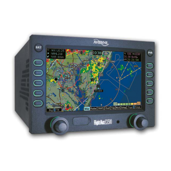
Map Page The Map page displays your flight plan and position as an overlay of a map of the current flight area (see Figure 2.1). The EX500/EX600 allows you to select the data you want to display on the Map page. -
Page 20: Figure 2.2 Metar And Air/Sig Keys
These keys are On\Off switches of the respective features. Figure 2.2 METAR and AIR/SIG Keys For 2-way Datalink, the EX500/EX600 does not display Note: graphical METARs for AWOS reporting stations that are more than 300nm from the current position or for ASOS reporting stations that are more than 450nm from the current position. - Page 21 For TWX670 cell information, see the WxOvly key > TWXCELL selection. Only one mode can be displayed on the EX500/EX600 MFD at any time. The EX500/EX600 provides scalable support for a number of different weather sensors so you can use the MFD to get the best view of hazardous weather and options to avoid it.
- Page 22 ◆ Terrain -Terrain data background with water and geo- political boundaries. ◆ Base - Black background with water and geo-political boundaries. ◆ None - Black background. Terrain scale is removed. Avidyne EX500/EX600 MFD -10- 600-00078-001 Rev 05...
- Page 23 Datalink RADAR for CONUS, including storm cells. For many operations, the EX500 displays weather data in the same way, regardless of which Datalink system is in use. Both systems provide datalink radar data—a composite image depicting precipitation as seen by multiple ground-based weather radar sites.
- Page 24 (such as storm cell movement and Datalink lightning). For Datalink RADAR, small areas of high-intensity datalink radar data might not be displayed on the EX500/EX600 at high range settings. Instead, larger areas of surrounding lower-intensity returns might obstruct indications of severe precipitation at Map ranges higher than 250 nm.
-
Page 25: Figure 2.3 Twxcell Mode Display
(EX600 Only) When panning with TWXCELL mode Note: displayed, cells further than the current range setting, centered on the the aircraft present position, will not be displayed. To see all cells when panning, select 200 nm range or greater. 600-00078-001 Rev 05 -13- Avidyne EX500/EX600 MFD... -
Page 26: Table 2.1Thunderstorm Activity (Cell) Colors
◆ RADAR - Displays on-board weather radar returns on the map. This choice does not appear if the EX500/ EX600 is not configured with an aircraft heading source, or if aircraft heading is currently unavailable. -
Page 27: Figure 2.4 Sat Ir Display
The Sat IR images are delivered with variable resolution of between approximately 10 km near the ownship to 30 km 100+ nm along the flight path. The EX500/EX600 smooths the edges of the SatIR images so that the images are not distracting at smaller zoom ranges. Like... - Page 28 Note: radar or SatIR data. If datalink radar or SatIR is unavailable in a particular area, hatched lines appear in that area. 3) The ACK is used to display and acknowledge system messages. Avidyne EX500/EX600 MFD -16- 600-00078-001 Rev 05...
-
Page 29: Panning (Ex600 Only)
If in panning mode, press to center the map on the own-ship symbol and exit panning mode. ■ If not in panning mode, press to enter panning mode and center the map on the last panned location. 600-00078-001 Rev 05 -17- Avidyne EX500/EX600 MFD... - Page 30 When panning with TWXCELL mode displayed, cells further Note: than the current range setting, centered on the the aircraft present position, will not be displayed. To see all cells when panning, select 200 nm range or greater. Avidyne EX500/EX600 MFD -18- 600-00078-001 Rev 05...
-
Page 31: Map Page Symbols-Terrain And Position
Map Page Symbols—Terrain and Position 2.3 Map Page Symbols—Terrain and Position The EX500/EX600 Map page uses included and optional sensors to depict the position of your aircraft in relation to the following: your flight plan, nearby airports, terrain, traffic, lightning, special use airspace and other navaids (see Figure 2.3). -
Page 32: Table 2.2 Track Indicator Graphics
In the example, the bottom storm cell, which includes the probability of hail, is moving NNE at 33 knots. The cell top is 35,000 feet high. Avidyne EX500/EX600 MFD -20- 600-00078-001 Rev 05... - Page 33 Before conducting a flight, always confirm the state of SUAs with FAA Flight Service. 8) Datalink Radar Status Box (EX500 only) - If more than three sensors are installed on the EX500, data for the datalink radar status is displayed at the bottom of the page instead of in the Sensor Status Box.
- Page 34 Terrain legend colors are shown in Terrain Display Color Coding on page 141. The displayed terrain and obstacle indicators are only advisory. It is dangerous to rely on the EX500/EX600 as the sole source of obstacle and terrain avoidance information. Always refer to current aeronautical charts for appropriate terrain and obstacle information.
-
Page 35: Map Page Symbols - Runways And Flight Plan
Figure 2.7 Map Page—Runways and Flight Plan Symbology 1) Airport Runway Diagrams - When the Map page is set to under 20NM, the EX500/EX600 displays runway layouts of the destination airport and nearby airports. 2) Flight Plan - Displays the active flight plan from the selected GPS on the map. - Page 36 Terrain Awareness system. The displayed terrain and obstacle indicators are only advisory. Do not rely on the EX500/EX600 as the sole source of obstacle and terrain avoidance information. Always refer to current aeronautical charts for appropriate terrain and obstacle information.
-
Page 37: Errors Displayed On The Map Page
2.5 Errors Displayed on the Map Page 2.5.1 Loss of GPS Input The loss of primary GPS on the EX500/EX600 is shown as follows: 1) The aircraft symbol is removed. 2) There is no heading information displayed (if GPS has been selected as your heading source/track). - Page 38 Map Page THIS PAGE INTENTIONALLY LEFT BLANK. Avidyne EX500/EX600 MFD -26- 600-00078-001 Rev 05...
-
Page 39: Traffic Mode And The Traffic Page (Optional)
This displays the dedicated traffic page to provide you with maximum traffic situational awareness. It is dangerous to rely on the EX500/EX600 as your sole source of data for collision avoidance. Traffic information is provided as an aid to your visual determination of traffic. -
Page 40: Traffic Advisories
Traffic key on the Map page. Target aircraft are displayed in standard format relative to current aircraft position. The available Traffic key modes are: ■ Avidyne TAS600 series (including 9900BX), Skywatch, and Bendix/King, TCAS - ABOVE, NORMAL, UNLIMTD, BELOW, and DSPLY OFF. ■... -
Page 41: The Traffic Page
3) Traffic Advisory - When a Traffic Advisory (TA) is reported from the traffic sensor, the traffic symbol of the threat aircraft turns yellow, and the EX500/EX600 displays a traffic alert message in the message bar (see Figure 3.1) to help focus your attention where it is needed. -
Page 42: Figure 3.2 Traffic Page
Pilot Guide. For TIS sensors, see the Aeronautical Information Manual. 2) Range Control - Turn the Range knob to select from the available ranges. For Traffic messages, see Traffic Messages on page 150. Note: Avidyne EX500/EX600 MFD -30- 600-00078-001 Rev 05... -
Page 43: Traffic Symbols
Traffic sensors do not provide any traffic awareness data for aircraft without operating transponders. Therefore, these aircraft will not be displayed on the EX500/EX600. It is your responsibility to see and avoid all other traffic and to maintain appropriate separation. -
Page 44: Tis Sensor Status
TIS data is not available at the current aircraft location. ● SBY - The TIS sensor is in standby mode. ● DATA FAIL - The TIS sensor has reported an internal fault. Traffic information is removed from display. Avidyne EX500/EX600 MFD -32- 600-00078-001 Rev 05... -
Page 45: Radar Page (Optional)
Radar Page (Optional) The radar-capable EX500/EX600 is designed to replace an existing radar indicator. Its user interface is more intuitive, and it is integrated with other sensors such as traffic and lightning (if installed). For convenience, the radar control functions used most frequently are on the left side of the Map page. -
Page 46: Map
OFF or in standby and your groundspeed (as received from the GPS system) falls below 20 Kts. If Auto Standby is enabled, the EX500/EX600 switches the radar to Standby automatically when ground speed falls below 20 Kts. -
Page 47: Dedicated Radar Page
Note: page 161. Dedicated Radar Page If your EX500/EX600 is radar-equipped, select Radar from the Page Bar to display the Radar page. Figure 4.2 Dedicated Radar Page 1) Tilt Indicator - Indicates the tilt angle and direction of the radar antenna: U for up, D for down with the amount of antenna tilt in quarter degrees using decimal notation. - Page 48 Tilt values are in degrees and range from D 15.00° (DOWN) to U 15.00° (UP). Range - The right inner knob controls the range scale. Turn the knob clockwise to increase the range scale and counter- clockwise to decrease the scale. Avidyne EX500/EX600 MFD -36- 600-00078-001 Rev 05...
- Page 49 Bendix/King - 5*, 10, 20, 40, 80, 160, 240, and 320nm, depending on radar/Type. Based on recommendations made by the FAA and the radar manufacturer, Avidyne recommends the following safety procedures: • At startup, if the radar is not being used in flight, ensure that it is turned off.
-
Page 50: Dedicated Radar In Ground Mode
3) Radar Standby - Places the radar circuitry in an energized but inactive state. Select Standby as soon as it is practical to do so after starting the EX500/EX600. When the radar is in standby, the mode annunciator is set to STBY, and the moving scan indicator and radar echo returns are not present. - Page 51 9) Control - Switches the bottom left key and top right three key functions to control the Settings as described in Typical Radar on page 40. Push Control again to bring the top right three key functions back to “Mode” as described above. 600-00078-001 Rev 05 -39- Avidyne EX500/EX600 MFD...
-
Page 52: Typical Radar
(Map, for example). The Message text is, “Heavy Radar Echoes Beyond 60nm”. The Message warning is cancelled when you acknowledge it (by pressing the ACK key), or when the alert is eliminated by the radar sensor. Avidyne EX500/EX600 MFD -40- 600-00078-001 Rev 05... - Page 53 4) Stab (Stabilization) - Turns the radar sensor gyro stabilization ON or OFF. An on-screen annunciation (STAB OFF) is displayed in the upper right hand corner when stabilization is turned OFF. 600-00078-001 Rev 05 -41- Avidyne EX500/EX600 MFD...
-
Page 54: Vertical Profile Mode
A vertical profile annunciation (PROFILE) provides the current azimuth displayed on the screen, in degrees left (L), right (R) or centered. Figure 4.5 Vertical Profile view (Bendix/King RDS 84VP/86VP and RDR 2000/2100) Avidyne EX500/EX600 MFD -42- 600-00078-001 Rev 05... -
Page 55: Radar Warnings
The MPEL boundary shown below applies only to units specifically approved for use with the EX500. The MPEL boundary shown below does not guarantee protection against ignition of flammable materials or damage to sensitive electronic equipment exposed to microwave energy from your radar. - Page 56 Radar Page (Optional) THIS PAGE INTENTIONALLY LEFT BLANK. Avidyne EX500/EX600 MFD -44- 600-00078-001 Rev 05...
-
Page 57: Taws Page (Optional)
Any display of yellow or red on the TAWS page indicates an imminent terrain hazard. The displayed terrain and obstacle indicators are only advisory. Do not rely on the EX500/EX600 as the sole source of obstacle and terrain avoidance information. Always refer to current aeronautical charts for appropriate terrain and... - Page 58 It indicates the current position of the scan. 4) Peaks Mode Elevations - Appears only when your EX500/ EX600 has been installed with the “Peaks Mode” option. The two numerical values correspond to the highest terrain/obstacle elevation displayed and the bottom elevation of the lowest color band displayed.
- Page 59 Range Annunciation that contains the new requested range. 9) Azimuth Lines (not shown) - On a 2-knob EX500, there is no Brg knob, so the bearing line feature is not available. Instead, there is an Azimuth Lines key. When pressed, labeled azimuth lines appear every 20 degrees.
- Page 60 100 feet or more, is not to be used for navigation. It is presented to provide the crew with additional situational awareness of true height above sea level upon which TAWS terrain alerting and display is based. Avidyne EX500/EX600 MFD -48- 600-00078-001 Rev 05...
-
Page 61: Taws Operation
When a caution alert is triggered, the terrain or obstacle that caused the alert displays in bright yellow, as shown below. Also, a message describing the nature of the alert is presented in the message bar. Figure 5.2 Terrain Caution Condition 600-00078-001 Rev 05 -49- Avidyne EX500/EX600 MFD... -
Page 62: Figure 5.3 Terrain Warning Condition
Display is being displayed, a terrain or obstacle alert message is displayed in the Message Bar. When you acknowledge this message, the EX500/EX600 automatically switches to the TAWS Display page. The message bar is removed from the display when the EGPWS is no longer in alert status, or if you acknowledge the message from the TAWS page. -
Page 63: Taws Reference
Traffic Page on page 29) is displayed. If a TA occurs while a terrain or obstacle alert is in progress, and the TAWS Display page is being displayed, the EX500 remains in TAWS Display and the TA message will appear in the Message Bar. - Page 64 TAWS Page (Optional) THIS PAGE INTENTIONALLY LEFT BLANK. Avidyne EX500/EX600 MFD -52- 600-00078-001 Rev 05...
-
Page 65: Cmax Chart Pages (Optional)
CMax Chart Pages (Optional) CMax™ charts is an optional Avidyne feature. It includes the following: instrument approach procedures, arrivals, departures, airport diagrams, and various taxiway and airspace diagrams typical of Jeppesen printed charts. CMax requires that you have a valid chart data subscription from Jeppesen Sanderson, Inc. -
Page 66: Chart Validity
(10) weeks out-of-date, access to the charts is revoked until a new chart data is loaded. On power up, if your EX500/EX600 is receiving a valid position from your GPS unit, the Chart page displays the airport diagram of your current position. -
Page 67: Cmax Procedure Charts
On landing, if the Chart page is displayed or subsequently selected, the EX500/EX600 switches automatically to the Airport diagram for the current location when the GPS Ground Speed drops below 40 knots. The Chart page shows the airport diagram of the current airport with ownship symbol for current aircraft position, if the airport diagram is geo-referenced. - Page 68 ■ 2-Knob EX500 - Use the keys on the right-hand side of the display labeled Up, Down, Left, and Right to manually move the chart on the screen (as shown in Figure 6.1).
-
Page 69: Figure 6.2 Plan Procedure Chart (4-Knob)
Other colors such as water or shaded terrain are also adjusted between Day and Night modes. The EX500/EX600 starts up with a default to Night mode. In a 2-knob EX500, the Day/Night key is on the bottom right corner (shown in Figure 6.1). -
Page 70: Cmax Chart Views
Northstar GPS units do not send non-active legs in approach Note: mode. Only the active leg will be depicted on the EX500/ EX600. The ownship symbol on the Chart page is always oriented Note: according to the current GPS ground track. -
Page 71: Procedure Views
Shows the descent minimums for the approach. The key legend shows the number of the current view as well as the total number of views available for that procedure (i.e., “1 of 4”, “2 of 4”, and so forth). 600-00078-001 Rev 05 -59- Avidyne EX500/EX600 MFD... -
Page 72: Figure 6.3 Procedure Chart Views
CMax Chart Pages (Optional) Header View Profile View Minimums View Figure 6.3 Procedure Chart views Avidyne EX500/EX600 MFD -60- 600-00078-001 Rev 05... -
Page 73: Airport Chart Views
Includes general chart information and communications frequencies. 3 of 4 Runways Shows runway information for the airport. 4 of 4 Departure Displays specific departure procedure information. Header View Runways View Departure View Figure 6.4 Airport Chart Views 600-00078-001 Rev 05 -61- Avidyne EX500/EX600 MFD... -
Page 74: Figure 6.5 Airport Departure Chart
Charts that cannot be split into smaller sections are shown as a complete chart, with the View key not displayed, since only one View type is available. Figure 6.5 Airport Departure chart Avidyne EX500/EX600 MFD -62- 600-00078-001 Rev 05... -
Page 75: Selecting An Airport
1) Airport Entry Field - This field accepts airport identification codes (such as KCAD, etc.). On startup, the field displays the current position airport. If the EX500/EX600 cannot determine a valid position, the field is left blank. Changing the Airport Entry Field depends on the type of EX500/EX600 you have: ■... - Page 76 The EX500/EX600 presents only those charts covered by Note: your Chart data subscription. The Charts are listed in the Jeppesen chart index order.
-
Page 77: Selecting A Chart
Chart page. Remember, when you press Display Chart the associated Airport diagram is also made available on the Chart page automatically when a procedure chart is loaded. 600-00078-001 Rev 05 -65- Avidyne EX500/EX600 MFD... - Page 78 If you observe any of these, reload the CMax chart data using the CMax data loader. If problems persist, contact your dealer or Avidyne Technical Support. As pilot in command, it is your duty to have backup sources of data available.
-
Page 79: Chart Notams Page
Chart Selection page. 2) Scroll knob - The Scroll knob scrolls the list of NOTAMs. If the list is longer than the screen area, scroll down to bring the remaining items into view. 600-00078-001 Rev 05 -67- Avidyne EX500/EX600 MFD... -
Page 80: European Vfr Charts
If a VFR chart is selected pressing "Display Airport" will display the VFR airport diagram. Likewise, if an IFR chart is selected, pressing "Display Airport" will display the standard Jeppesen airport diagram. Avidyne EX500/EX600 MFD -68- 600-00078-001 Rev 05... -
Page 81: Trip Page
Trip Page The Trip page shows the remaining legs in the current flight plan and other data being received by the EX500/EX600 from the GPS. The Trip page is split horizontally into two sections. About the Trip Page The upper portion of the Trip page displays the following: ●... -
Page 82: Trip
H:MM format for each flight plan leg at current ground speed. ◆ ETA - Estimated time of arrival to waypoint in HH:MM formatted for local time. ◆ METAR - Graphical METAR and reporting point identifier. Avidyne EX500/EX600 MFD -70- 600-00078-001 Rev 05... - Page 83 JeppView subscription coverage. For more information, see Chapter 6 "CMax Chart Pages (Optional). ■ When the EX500/EX600 Datalink is enabled, any leg on your flight plan that is longer than 100NM generates “intermediate waypoints” to display en route weather. These points are identified with a Wx: prefix, rather than To: in the flight plan display.
-
Page 84: Figure 7.2 Datalink Legend
- If 2-Way Datalink is installed and available, the double-headed arrow Status key displays signal information for the 2-Way Datalink system. It also displays the elapsed time since the last reception of the various types of weather data. Avidyne EX500/EX600 MFD -72- 600-00078-001 Rev 05... - Page 85 Aux page. When these messages are displayed, all data for that product is removed from the MFD. The Trip page will indicate that new data for that product has 600-00078-001 Rev 05 -73- Avidyne EX500/EX600 MFD...
- Page 86 0 indicates no errors. ◆ Signal Lock (WSI Receiver only) - Displays whether the receiver was able to obtain lock on the satellites in view. It will display either “locked” or “not locked”. Avidyne EX500/EX600 MFD -74- 600-00078-001 Rev 05...
- Page 87 If wind data for a particular flight level has not been received, Note: the message, Not Available, is displayed. If the EX500/ EX600 has received wind data, but the value is undefined for a particular level, the wind value is displayed as dashes. This can happen for a number of reasons;...
- Page 88 Unit selections apply to decoded METAR text on both the Note: Trip page and Nearest page. The Units key is only displayed when the legend is selected Note: as the Trip page display. Avidyne EX500/EX600 MFD -76- 600-00078-001 Rev 05...
-
Page 89: Airport Information Page
Trip page. Use the GPS as the primary source of navigation information for approach procedures. Consult your avionics installation facility to determine if your EX500/EX600 is interfaced to the Garmin GNS-430 via ARINC 429 or RS-232. Airport Information Page Figure 7.3 Trip Airport Information Page... - Page 90 Trip Page THIS PAGE INTENTIONALLY LEFT BLANK. Avidyne EX500/EX600 MFD -78- 600-00078-001 Rev 05...
-
Page 91: Nearest Page (Nrst)
METAR reporting station for which an Instrument Procedure chart is available. An “I” on the icon indicates that at least one ILS approach chart is available. See Chart, below, for more information. 600-00078-001 Rev 05 -79- Avidyne EX500/EX600 MFD... - Page 92 VORs - Identifier, bearing, distance, frequency and name. ■ NDBs - Identifier, bearing, distance, frequency and name. ■ Intersections - Identifier, bearing, distance, frequency and name. ■ Obstacles - MSL (and AGL) height, bearing and distance. Avidyne EX500/EX600 MFD -80- 600-00078-001 Rev 05...
-
Page 93: Airport Information Page
6) Select knob - Moves the cursor to a specific airport or other data. Airport Information Page Figure 8.2 NRST Airport Information Page 1) Back to Nearest - Returns to the currently selected NRST page. 600-00078-001 Rev 05 -81- Avidyne EX500/EX600 MFD... - Page 94 Step and Jump labels appear. ■ Step - Scrolls the page one line. ■ Jump - Scrolls an entire page (or to the end of the list). Avidyne EX500/EX600 MFD -82- 600-00078-001 Rev 05...
-
Page 95: Aux Page
Aux Page This chapter describes the options on the EX500/EX600 Aux page and tells you how to configure them (see Figure 9.1). You also use the main Aux page to view informational messages (see call-out 6 in Figure 9.1.) Aux Main Page The options and features on the EX500/EX600 Aux page are identified by call out in Figure 9.1, and the list below the Figure... - Page 96 6) Message List (including sensor status) - This display area is for system informational messages on the EX500/EX600. This list is not chronological—each type of sensor is assigned to a position in the list for its related messages.
-
Page 97: Airport Filter Setup
The Airport Filter page allows you to set the criteria for limiting the airports that are displayed on the Map page and Nearest page. Figure 9.2 EX500 Airport Filter Setup 1) Airport Type - Selects the display of Towered, Non-Towered, or both. -
Page 98: Declutter Setup
■ Off - The symbol is never displayed. The EX500/EX600 may limit the number of symbols Note: displayed based on the total symbol density. 3) Label - Checking the label box displays the navaid label along with the symbol. - Page 99 Note: 4) Range Dots - The dots represent the available map scales. A blue dot indicates that the object is displayed at that range. The vertical dash line indicates the map current scale. 600-00078-001 Rev 05 -87- Avidyne EX500/EX600 MFD...
-
Page 100: Data Block Setup
3) Data Block - Allows up to 3 lines of data for display. The data block resizes automatically based on the number of lines selected. The data block is not displayed if all the lines are set to “-Blank-.” Avidyne EX500/EX600 MFD -88- 600-00078-001 Rev 05... -
Page 101: System Time Setup
Most RS232 GPS interfaces do not provide time data. Note: ■ Auto - The system tries to set the time automatically by obtaining data first from the GPS and then from the 2-Way Datalink system, if installed. 600-00078-001 Rev 05 -89- Avidyne EX500/EX600 MFD... - Page 102 4) Current Time and Date settings - Displays the time/date values currently being reported by the GPS and Datalink as well as the Local and UTC values that are currently set in the EX500/EX600. You cannot change Local time directly – you must first set the Note: GMT time correctly and then choose the correct Time Zone.
-
Page 103: Datalink (Optional)
EX500/EX600 Map and Trip pages. Avidyne offers the following Datalink services for the EX500/EX600: ● Broadcast Datalink ● Two-Way Datalink ● Multilink For most operations, the EX500/EX600 weather data display is the same regardless of which Datalink system is in use. 600-00078-001 Rev 05 -91- Avidyne EX500/EX600 MFD... -
Page 104: Broadcast Datalink
Datalink (Optional) 10.1 Broadcast Datalink The EX500/EX600 supports an optional Broadcast Datalink receiver, either: ● An MLB700 that supports WSI/Sirius ● An XM receiver that supports XM WX. XMD076 for XM Broadcast Reception EX500 MFD MLB700 for Sirius Broadcast Reception Figure 10.1 Broadcast Receiver Options... - Page 105 In the mountains and off the coast, hatched lines may represent no coverage below 10,000 feet. If there are radar returns in that region above FL100, the returns will be displayed as “islands of precipitation” surrounded by the hatched lines. 600-00078-001 Rev 05 -93- Avidyne EX500/EX600 MFD...
-
Page 106: Two-Way Datalink
Orbcomm Satellite North American Access Figure 10.2 Two-Way Datalink The 2-Way Datalink transceiver sends your flight plan to the Avidyne Network Operations Center (NOC), which then sends you only the data pertinent to your flight. Two-Way Datalink can provide the lowest-cost datalink by charging only for the data used. -
Page 107: Flight Tracking
Note: view of the sky and, generally, will not work inside a hangar. When you enter a flight plan or a direct-to waypoint, the EX500/ EX600 automatically downloads the weather for your route of flight. Additional updates are provided in-flight, based on the settings that you selected online or on the EX500/EX600’s Datalink Setup page. -
Page 108: Loss Of Satellite Coverage
The loss of satellite coverage for your Datalink function will not adversely affect the remaining navigation, map, radar, etc. functions of your EX500/EX600. If installation problems and/or satellite network problems do occur, you will be able to determine this by observing: ●... - Page 109 All signal strength indicators are dashed (“- - -”). There is no action that you can take to re-acquire a satellite signal in the event of satellite and/or network problems. The EX500/EX600 will continue to try to acquire satellites as long as Datalink is enabled.
-
Page 110: Multilink
All weather data (Datalink Radar, Text and Graphical METARs, AIRMETs, SIGMETs and TFRs) are depicted as usual whether received from Broadcast or from 2-Way Datalink. No specific action is required to choose between Datalink systems for this data. Avidyne EX500/EX600 MFD -98- 600-00078-001 Rev 05... - Page 111 In the MFD status message: Note: Narrowcast refers to the use of 2-way datalink to send weather data from the Avidyne NOC based on position and flight plan data. Broadcast refers to the external Sirius or XM satellite weather receiver. Datalink refers to the 2-Way Datalink system.
-
Page 112: Overview Of Datalink Weather
Datalink (Optional) 10.4 Overview of Datalink Weather For most operations, the EX500/EX600 displays weather the same way regardless of which Datalink system is used. Two-Way Datalink and Broadcast systems can provide the following: ● Datalink Radar - A composite image depicting precipitation as seen by multiple ground-based weather radar sites. -
Page 113: Figure 10.6 Graphical Metar Symbols
Map page, Trip page, and on both types of Nearest Airport pages. They allow a “big-picture” view of general weather conditions in an area. The presence of a graphical METAR does not necessarily mean that the corresponding Text METAR is viewable. 600-00078-001 Rev 05 -101- Avidyne EX500/EX600 MFD... - Page 114 Map page for which the FAA has issued some type of flight restriction. Contact a local Flight Service Station (FSS) for information. The EX500/EX600 does not display any details of the flight restriction. Do not rely on the...
-
Page 115: Setting Up Datalink For Iridium
Figure 10.7 Datalink Setup Page Use the Select key (2-knob EX500) or Select knob (4-knob EX500/ EX600) to move from field to field and rotate the Change knob to select choices for an option. Press Save to save changes. - Page 116 Coverage Radius to either side of the flight plan route. The boundary of the datalink radar coverage area is shown by an outline with diagonal stripes. Avidyne EX500/EX600 MFD -104- 600-00078-001 Rev 05...
- Page 117 To enable a weather type, check the checkbox for that weather. The following weather data subscriptions can be enabled or disabled: ● Text METARs - Text METARs ● METAR Symbols - Graphical METAR flag symbols 600-00078-001 Rev 05 -105- Avidyne EX500/EX600 MFD...
- Page 118 Do not rely on the as your sole source for EX500/EX600 TFRs. The status of TFRs may change or may be unavailable. Before conducting a flight, always confirm the state of TFRs with FAA Flight Service. Avidyne EX500/EX600 MFD -106- 600-00078-001 Rev 05...
-
Page 119: Iridium Text Messaging
You can address messages to either a phone number that supports text messaging or to an e-mail address. Avidyne strongly recommends using e-mail addresses since Note: text messages over Iridium are much more reliable when sent to e-mail addresses as opposed to phone numbers. -
Page 120: Managing Messages
● Save Contact - Saves the address in the header in the Contacts list. Goes to the Contacts page and allows you to enter the contact information (name, e-mail address, or phone number). Avidyne EX500/EX600 MFD -108- 600-00078-001 Rev 05... -
Page 121: Table 10.1 Message Status
A solid green arrow indicates a from Flight Center message received from your Flight Center via MyAvidyne.com Message received A solid blue arrow indicates a message from Avidyne NOC received from the Avidyne Network Operations Center (NOC) 600-00078-001 Rev 05 -109- Avidyne EX500/EX600 MFD... -
Page 122: Managing Contacts
Compose - Goes to the Compose page with the contact’s address inserted in the To: field, and the message body ready to enter a message. ● Edit - Opens a selected contact so that you can make changes to the contact information. Avidyne EX500/EX600 MFD -110- 600-00078-001 Rev 05... -
Page 123: Composing An Iridium Text Message
● Next DL Page - Opens the Setup page. ● Send - Sends the message. ● Change Field - Moves the cursor back and forth between the To: field and the Message: field. 600-00078-001 Rev 05 -111- Avidyne EX500/EX600 MFD... - Page 124 Select Character - Turn the inner Select knob to select letters from an alphanumeric set (A-Z, punctuation, 0-9, and space). ◆ Position Cursor - Turn the outer ring of the Pos knob to move the cursor position within the Compose text box. Avidyne EX500/EX600 MFD -112- 600-00078-001 Rev 05...
-
Page 125: Setting Up Datalink For Orbcomm (Release 4.0 And Earlier)
1) Datalink Defaults - Press Datalink Defaults to reset the Datalink Setup options to the following default values: ■ Coverage area—Flight Plan ■ Coverage Area—200 NM ■ NEXRAD Resolution—Medium ■ Request Interval—Normal Mode ■ METARS and AIRMETS/SIGMETS —ON 600-00078-001 Rev 05 -113- Avidyne EX500/EX600 MFD... - Page 126 Datalink Radar resolution. The “Low” setting uses the least message units and most likely will provide the fastest updates. Increasing this setting provides improved Datalink Radar details, but, in turn, increasing the message units can decrease the actual update rate. Avidyne EX500/EX600 MFD -114- 600-00078-001 Rev 05...
- Page 127 ■ AIRMETs / SIGMETs - AIRMET/SIGMET ■ SUA Status - Special Use Airspace (SUA) status. The Avidyne NOC does not support SUA Status. Note: Some data types do not change often during the day and will Note: therefore be updated only when they change.
-
Page 128: Optimizing Multilink For Orbcomm (Release 4.0 And Earlier)
Datalink (Optional) Do not rely on the EX500 as your sole source for TFRs. The status Note: of TFRs may change or may be unavailable. Before conducting a flight, always confirm the state of TFRs with FAA Flight Service. 8) Save - Saves any changes made and return to the Aux page. - Page 129 MultiLink enabled. This will cause the system to use a minimum of 2-Way Datalink data on each flight for session management and position reporting. 600-00078-001 Rev 05 -117- Avidyne EX500/EX600 MFD...
-
Page 130: Orbcomm Text Messaging (Release 4.0 And Earlier)
Do not use Datalink Messaging in terminal or high traffic areas. To access the Datalink Messaging page, press the Datalink Setup key on the Aux page. Avidyne cannot guarantee the privacy of your Datalink Note: Messaging communications. For more information, see the Avidyne Privacy Policy on www.MyAvidyne.com. -
Page 131: Figure 10.15 Datalink Messaging Page
5) Message Text - The text of the message. Text color indicates the source of the message as follows: Color Heading Green Messages received from the ground. White Messages entered into the EX500/EX600 for transmission. Blue Messages received from the Avidyne NOC. 600-00078-001 Rev 05 -119- Avidyne EX500/EX600 MFD... - Page 132 10) Scroll Up / Scroll Down (Not shown) - These keys appear if the message display area is full and new messages are sent or received. Press either key to scroll the message display area up or down by one full message. Avidyne EX500/EX600 MFD -120- 600-00078-001 Rev 05...
-
Page 133: Composing And Sending A Message
Messages sent from the ground to the airplane will be re- Note: attempted for 24 hours. It is possible to miss a message that was sent after landing, and receive it the next day. 600-00078-001 Rev 05 -121- Avidyne EX500/EX600 MFD... -
Page 134: Receiving A Message
Figure 10.16 Incoming Message Alert 2) To view the new message, turn to the Aux page and select Datalink. The full text of the new message is displayed in the message display area. Avidyne EX500/EX600 MFD -122- 600-00078-001 Rev 05... -
Page 135: Reference
Lightning Messages, page 151 ● Two-Way Datalink Messages, page 154 ● Broadcast Datalink Messages , page 156 ● TAWS Messages, page 159 ● Radar Messages, page 161 ● Abbreviations and Definitions, page 163 600-00078-001 Rev 05 -123- Avidyne EX500/EX600 MFD... -
Page 136: Activating Broadcast Datalink Accounts
Broadcast Radio Serial Number (ID Number) To obtain the ID of the Broadcast receiver installed in your aircraft, open the EX500/EX600 Trip page. Press the Display key until “↓ Status” (Broadcast Datalink status) is shown, and carefully enter your Radio Serial Number. -
Page 137: Completing The Wsi Weather Activation
To complete the activation: 1) Move your aircraft outside to an area with a clear view of the sky. 2) Power up both the EX500/EX600 and the Broadcast receiver and wait at least 30 minutes to allow the MLB700 to receive the activation signal. -
Page 138: Activating Sirius Audio
The Audio Package you want (details available at www.sirius.com). Choose the Audio service you want based on the channels that you would like to receive. ● Audio s/n - Power up your Avidyne Remote Control. The s/n is located on the first screen. ● Credit Card Information... - Page 139 MLB700. 5) After the second power cycle, when your receiver receives the activation code, music can be heard through the pilot’s audio panel. There is no interface between EX500/EX600 and the Sirius Note: Audio receiver. 600-00078-001 Rev 05...
-
Page 140: Activating Xm Wx Satellite Weather
To verify that your receiver is activated: 1) Move your aircraft outside to an area with a clear view of the sky. 2) Power up both the EX500/EX600 and the Broadcast receiver and wait at least an hour to allow the receiver to receive the activation signal. - Page 141 Activating Broadcast Datalink Accounts The EX500/EX600’s Service Level indication may take Note: several flights to synchronize to the correct level but you will still receive and see the weather products you have purchased. Contact Heads Up Technologies for problems relating to your Note: receiver or assistance with service.
-
Page 142: Activating A 2-Way Datalink Account
You can set your 2-Way Datalink user preferences online prior to your flight. The preferences will be downloaded to your EX500/EX600 via satellite the next time you fly. Avidyne EX500/EX600 MFD -130-... -
Page 143: Setting Up Multilink
If the Flight Center key is not displayed on your MyAvidyne Note: page, the NOC has not yet detected the Broadcast receiver. Try activating the Broadcast receiver again as described in What is Next? on page 125. 600-00078-001 Rev 05 -131- Avidyne EX500/EX600 MFD... -
Page 144: Cleaning The Ex500/Ex600 Screen
A cleaning solution composed of de-ionized water or isopropyl alcohol (IPA). The EX500/EX600 screen is made of a plastic film that is vulnerable to scratches, damage by a sharp articles or improper cleaners. Use care when cleaning. Always apply the cleaning solution directly onto the cloth. -
Page 145: Updating Your Databases
Updating Your Databases 11.5 Updating Your Databases 11.5.1 Types of Databases The EX500/EX600 can contain up to four separate databases. They are: ™ ■ CMax Chart Data is an optional Avidyne feature that allows you to view JeppView Charts on your EX500/EX600. -
Page 146: About Portable Usb Devices
About Portable USB Devices You can use a portable USB device (either a Zip Drive or a USB Flash Memory Drive) to move data between your PC and the EX500/ EX600. For more information about the databases and about loading data from your PC to a portable USB device, see the Avidyne Data Update Guide (P/N 600-00148-000). - Page 147 Updating Your Databases This section describes how to move data from a portable USB device (a 250MB Zip Drive or USB Flash Memory Drive) to the EX500/ EX600. If using a Zip Drive Dataloader: • Do not let the portable Zip Drive dangle by the cable. It can result in damage to your MFD or the Drive, as well as a dataload failure.
-
Page 148: Loading Navdata (The Navigation Database)
It can also cause an intermittent connection, which will result in an unsuccessful data update. 4) Turn on the EX500/EX600. If you are using a Zip Drive, insert the Zip disk into the Zip Drive when the initial FlightMax logo screen is displayed. -
Page 149: Loading Cmax Chart Data
. For a Zip Drive, there is no disk or the disk was not found. . The Zip Disk is incorrectly formatted. 5) Press Proceed to start the update. Do not turn off the EX500/ EX600 or disconnect the cable during a data load.The data load is complete when the, “Press Any Bezel Key”... - Page 150 It can also cause an intermittent connection, which will result in an unsuccessful data update. 2) Turn ON the EX500/EX600. If you are using a Zip Drive, insert the Zip disk into the Zip Drive when the initial FlightMax logo screen is displayed.
- Page 151 6) When the operation has been completed, the EX500/EX600 will display the, “Press any Bezel Key” message. 7) At this point, turn OFF power to the EX500/EX600, remove your portable USB device, and then turn the EX500/EX600 power back on.
-
Page 152: Taws Display Color Coding
Black No significant terrain/obstacle. 16% Blue Peaks only. Water at sea level elevation (0 feet MSL). Magenta Unknown terrain. No terrain data in the data base for the Dots magenta area shown. Avidyne EX500/EX600 MFD -140- 600-00078-001 Rev 05... -
Page 153: Terrain Display Color Coding
>=3,000 and <5,000 Yellow >=2,500 and <3,000 Darkest Green >=2,000 and <2,500 Darker Green >=1,500 and <2,000 Greens >=1,000 and <1,500 Greens >=500 and <1,000 Lighter Green >=0 and <500 Lightest Green <0 600-00078-001 Rev 05 -141- Avidyne EX500/EX600 MFD... -
Page 154: Sensor Status Block Symbols
Weather Overlay 2-Way Datalink Weather Overlay Traffic A solid yellow symbol indicates that the EX500/EX600 is unable to display data from that particular sensor. This may be Lightning due to a communication error, the sensor Broadcast Datalink is not healthy, or there is a configuration Weather Overlay problem. -
Page 155: Map Symbols
The Map orientation is indicated in the triangle to the right of the H/T Block. 11.9.2 Map Symbols—Navigational Fixes The EX500/EX600 can display the following database items: ● Airports ● Navaids (VORs, NDBs and Waypoints) ●... -
Page 156: Table 11.5 Map Symbols-Navaids
Table 11.5 Map Symbols—Navaids Symbol Item Heading All NDBs All VORs Intersection Terminal, Jet, and Victor airway waypoints (intersections) Table 11.6 Map Symbols—Airports Surface Airport Type Hard Soft Water Towered Towered Non-Towered Non-Towered Avidyne EX500/EX600 MFD -144- 600-00078-001 Rev 05... -
Page 157: Table 11.7 Map Symbols-Other
Obstacles within 1NM of each other >= 1000’ AGL Flight Plan, Course Waypoints If all the legs are shown in white, the GPS is not reporting the Note: active leg of the flight plan. 600-00078-001 Rev 05 -145- Avidyne EX500/EX600 MFD... -
Page 158: Map Symbols-Line Styles
For adjacent or overlaying types of Special Use Airspace (e.g., Restricted Areas or Prohibited Areas within larger MOAs), some masking of the border lines might occur. As pilot in command, you must reference current aeronautical charts for accurate boundaries. Avidyne EX500/EX600 MFD -146- 600-00078-001 Rev 05... -
Page 159: Table 11.10 Airmet And Sigmet Boundary Lines
Table 11.10 AIRMET and SIGMET Boundary Lines Line Color Type Label Bright blue Mountain AIRMET Dark yellow IFR AIRMET Orange Turbulence AIRMET TURB Blue Icing AIRMET Dark Red SIGMET AIRMET Blue grey Convective SIGMET CSIG 600-00078-001 Rev 05 -147- Avidyne EX500/EX600 MFD... -
Page 160: Data Block Information
FMS by the pilot. Use this display to verify what has been put into the FMS/GPS. Do not rely on the BARO ALT Data Blocks for terrain separation. Use your altimeter or other instrument. Avidyne EX500/EX600 MFD -148- 600-00078-001 Rev 05... -
Page 161: Nav Messages
EX500 is attempting to Acknowledge Reconnecting… reconnect to the port that is connected to the GPS/ FMS. Nav Source is Not EX500 does not detect any Have maintenance Communicating data being sent from the check configuration GPS/FMS. and installation Nav Source Data... -
Page 162: Traffic Messages
Map Heading check configuration source and a “fatal and installation heading fault” is received. Traffic Heading Traffic sensor is configured Acknowledge Source is Valid as the Map Heading source and is valid. Avidyne EX500/EX600 MFD -150- 600-00078-001 Rev 05... -
Page 163: Lightning Messages
Lightning Sensor is Lightning source is in Have configuration in Noise- Monitor Noise- Monitor Mode. checked at an Avidyne Mode Authorized Entegra Service Center. Lightning Sensor is Lightning source is in Have configuration in Demo Mode Demo Mode. - Page 164 Recommended Pilot Messages & Colors Action Lightning Heading Stormscope is configured Have configuration Source Failed as a heading source and checked at an Avidyne a “fatal heading fault” is Authorized Entegra received. Service Center. Lightning Heading Stormscope is configured Acknowledge.
- Page 165 The position reporting Cycle position sen- (TWX670 only) source (GPS or FMS) sor power. connected to the TWX670 is not sending Have configuration position data. checked at an Avidyne Authorized Entegra Service Center. 600-00078-001 Rev 05 -153- Avidyne EX500/EX600 MFD...
-
Page 166: Two-Way Datalink Messages
Lightning information is Acknowledge > 20 minutes older than 20 minutes. Narrowcast Data not Datalink is Enabled and Acknowledge yet received no Datalink data has been received within 10 minutes of EX500/ EX600 initialization complete. Avidyne EX500/EX600 MFD -154- 600-00078-001 Rev 05... - Page 167 15 minutes of the initial Datalink update. Datalink: Idle No data being sent or None necessary. received. NXR Invalid Datalink Radar Wait for next temporarily not able to Datalink Radar update. be displayed. 600-00078-001 Rev 05 -155- Avidyne EX500/EX600 MFD...
-
Page 168: Broadcast Datalink Messages
Pilot Action Broadcast Receiver EX500/EX600 Have the wiring from Not Communicating the broadcast receiver received no data from to the EX500 inspected. the broadcast receiver for 10 minutes Broadcast Antenna The Broadcast Datalink Have the Broadcast is Disconnected antenna or cable is not... - Page 169 Broadcast METAR data Monitor Broadcast > 120 min age since creation is system during flight, greater than 120 have system inspected minutes. METAR data if performance does not can no longer be improve. displayed. 600-00078-001 Rev 05 -157- Avidyne EX500/EX600 MFD...
-
Page 170: Table 11.16 Broadcast Datalink Messages
Broadcast TFR data age Monitor Broadcast 90 min since creation is greater system during flight, than 120 minutes. TFR have system inspected data can no longer be if performance does not displayed. improve. Avidyne EX500/EX600 MFD -158- 600-00078-001 Rev 05... -
Page 171: Taws Messages
EGPWS control panel, the correct. If the EGPWS TAWS Display page is is not inhibited and if painted with magenta dots this message persists, overlaid by the large text contact maintenance. annunciation TAWS DISPLAY INHIBITED. 600-00078-001 Rev 05 -159- Avidyne EX500/EX600 MFD... - Page 172 EX500/EX600 check configuration and installation. Whenever the TAWS Display is unavailable due to this failure, the TAWS Display page is painted with magenta dots overlaid by the large text annunciation TAWS NOT COMMUNICATING. Avidyne EX500/EX600 MFD -160- 600-00078-001 Rev 05...
-
Page 173: Radar Messages
Automatic Radar ON, Auto Standby is Take care to turn Radar Standby Disabled selected, and ground speed OFF upon landing, as is invalid. the “Speed below 20KT” caution will not be provided 600-00078-001 Rev 05 -161- Avidyne EX500/EX600 MFD... - Page 174 Radar Failure The Radar system has Momentarily select failed. This error will not be Standby, then reselect EX500/ mode. Have cleared until the maintenance check R/T. EX600 is shut down and restarted. Avidyne EX500/EX600 MFD -162- 600-00078-001 Rev 05...
-
Page 175: Abbreviations And Definitions
Tactical Air Navigation Terminal Aerodrome Forecasts Traffic Advisory System True Air Speed TAWS Terrain Awareness and Warning System TCAD Traffic and Collision Alert Device TCAS Traffic Alert Collision Avoidance System Temporary Flight Restrictions 600-00078-001 Rev 05 -163- Avidyne EX500/EX600 MFD... - Page 176 Visual Flight Rules Victor Airways Aerial highways that connect electronic navigation aids (more traffic). Victor Airways are 8 nautical miles wide (4 NM either side of the centerline) VHF Omnidirectional Radio Beacon Weather Avidyne EX500/EX600 MFD -164- 600-00078-001 Rev 05...
-
Page 177: Using Ex500/Ex600 Outside The Us
Avidyne provides data only for North America (including the United States and Canada). ● XM WX Weather—XM WX Satellite Weather (Broadcast Datalink), and therefore the EX500/EX600 Datalink features, are not currently available outside North America. ● WSI\SIRIUS Weather—WSI\SIRIUS Satellite Weather (Broadcast Datalink), and therefore the EX500/EX600 Datalink features, are not currently available outside North America. -
Page 178: Features Available In Other Parts Of The World
South America, call +1-303-799-9090, for eastern hemisphere, including Europe, call +49 6102 5070). ● Terrain Data—Avidyne provides terrain data for two areas: the Americas (North and South America), and International (excluding Americas). If you are flying in an area where your current terrain data is not supported, terrain will not display (similar to the Base view on the Map page). -
Page 179: Avidyne Exclusive Limited Warranty
(c) The Product has not been altered in any manner other than as previously authorized by Avidyne in writing; and (d) Repairs to the Product have not been made by anyone other than Avidyne or an Avidyne authorized service facility. - Page 180 RELATED TO PRODUCTS NOT MANUFACTURED BY AVIDYNE OR REGARDING OR RELATED TO THE PERFORMANCE OR RELIABILITY OF ANY SUCH PRODUCT, EITHER ALONE OR WHEN USED WITH ANY PRODUCT MANUFACTURED BY AVIDYNE, OR THE SUITABILITY OF ANY SUCH PRODUCT FOR USE WITH ANY PRODUCT MANUFACTURED BY AVIDYNE.
-
Page 181: Software License
License and Certain Restrictions You may use the Software on the EX500/EX600 on which it was delivered. You may not copy the Software for any purpose. You may not transfer the Software or any rights under this Agreement to another party without this Agreement. - Page 182 Agreement, understand it, and agree to be bound by its terms and not those contained in your purchase order. If you do not agree to the terms of this license, Avidyne is unwilling to license the product to you. In such event, you may not use or copy the product, and you should promptly contact Avidyne for instructions on return of the unused product(s) for a refund.
- Page 184 AVIDYNE CORPORATION 55 Old Bedford Road Lincoln, MA 01773 Telephone: +1-781-402-7400 Toll Free (US): 800-AVIDYNE (800-284-3963) FAX: +1-781-402-7599 www.avidyne.com P/N 600-00078-001 Rev 05 March 10, 2011...
Need help?
Do you have a question about the EX500 and is the answer not in the manual?
Questions and answers