
Subscribe to Our Youtube Channel
Related Manuals for Avidyne EX500


Summary of Contents for Avidyne EX500
- Page 1 Release 3 and Later Installation Manual 700-00007-(), 700-00167-() P/N 600-00175-000 Rev 04...
- Page 3 700-00167-(), EX600 All materials copyrighted including images that represent this software Copyright 2009 Avidyne Corporation. All rights reserved. The latest revision of the EX500/EX600 MFD Installation Manual is made available to authorized Avidyne dealers on www.avidyne.com the web at Avidyne®, FlightMax®, FMX®, and TCAD® are registered trademarks of Avidyne Corporation.
- Page 4 14 CFR Part 23 Class I, II, and III aircraft, as defined in Advisory Circular AC 23 1309-1C, which are listed in the AML. When installed in Class III aircraft, if the EX500 replaces a Radar display, an independent lightning detection and display system complying with...
-
Page 5: Table Of Contents
4.6.3 Weight and Balance Calculation................... 17 4.7 Selecting the Heading Source....................... 18 4.8 Datalink Antenna Installation Considerations................18 4.8.1 ORBCOMM Antenna Details (EX500 Release 4.0 and earlier only) ........19 4.8.2 Broadcast Antenna Details ....................19 4.9 Wiring External Devices ........................ 20 4.9.1 GPS and FMS Wiring ......................20... - Page 6 6.1.3 System Info > Port Info Page....................70 6.2 Electro-Magnetic Interference (EMI) Check .................. 71 6.3 TWX670 Lightning Sensor Strike Test ..................71 6.4 WX-500 Lightning Sensor Strike Test ................... 72 6.5 Traffic Test ............................ 72 6.6 ORBCOMM Satellite Reception (EX500 Only) ................72 - iv -...
- Page 7 Appendix C: STC Permissions ....................85 Appendix D: EX500, EX600, Tray & Panel Dimensions ............86 Appendix E: ORBCOMM Two-Way Datalink Antenna Installation (EX500 Only) ....94 Appendix F: EX500/EX600 General Wiring ................95 Appendix G: GPS/FMS System Wiring .................. 96 Appendix H: Lightning and Datalink Sensor Wiring.............
- Page 8 Figure 29: EX600 Helicopter Tray Support Structure Panel...............90 Figure 30: EX500 and Tray Dimensions..................... 91 Figure 31: EX500 Panel Cut-Out Dimensions .................... 92 Figure 32: EX500 Tray Support Structure Panel ..................93 Figure 33: Installing the 2-Way Datalink Antenna ..................94 Figure 34: EX500/EX600 General Wiring....................95 Figure 35: GPS/FMS Sub-System Wiring ....................
- Page 9 List of Figures Figure 44: RDR-1300 RADAR Direct Connect Wiring................105 Figure 45: RDR-1300 RADAR w/Adaptor Cable Wiring ................106 Figure 46: WXR250/270/300 RADAR w/ Adaptor Cable Wiring...............107 - vii -...
- Page 10 List of Tables Table 1: EX500 Technical Specifications ..................... 4 Table 2: EX600 Technical Specifications ..................... 4 Table 3: Sensor Port Configuration Options....................5 Table 4: Main Connector (P2) Pin Assignments................... 7 Table 5: ARINC Port Pinout Cross-Reference ..................... 8 Table 6: RS-232 Port Pinout Cross-Reference ....................
-
Page 11: About The Ex500/Ex600 Mfd
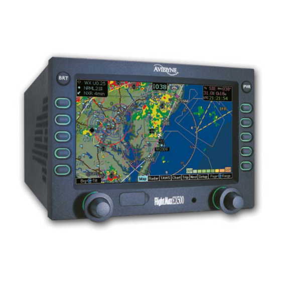
About the EX500/EX600 MFD 1 About the EX500/EX600 MFD The Avidyne Multi-Function Display, or MFD, is a single unit computer system mounted in an aircraft instrument panel in the pilot's view that interfaces to various aircraft avionics. The MFD increases pilot situational awareness and enhances flight safety by providing supplementary navigation, traffic, terrain, airspace, weather, and approach chart information. - Page 12 Supports either: ■ External MLX770 Iridium Datalink Transceiver EX500 Release 4 or greater software is required to support the MLX770 Iridium Datalink Note: Transceiver. All Iridium or MLX770 references in this document assume Release 4 or greater software is installed in the EX500.
-
Page 13: General Information
➥ Avidyne strongly recommends that you review the Pilot’s Guide before operating the MFD. The current version of the EX500/EX600 Multi-Function Display Pilot's Guide is available on the web at www.avidyne.com. The conditions and tests required for TSO approval of this article are minimum performance Note: standards. -
Page 14: Mfd Technical Specifications
Installation Manual MFD Technical Specifications P/N 600-00175-000 Rev 04 2.2 MFD Technical Specifications Table 1: EX500 Technical Specifications Standard Features Display High Brightness Sunlight Readable Color AMLCD Diagonal size 5.5 inches Interfaces RS-232, ARINC 429, ARINC 453, ARINC 407 & TTL... -
Page 15: Configuration Options
To support the many sensor types encountered in the typical aircraft installation, the installer must configure the EX500/EX600 for the sensor type and select the correct port configuration. Table 3 lists sensor options and their associated port configurations. This data may be used when executing Maintenance Mode sensor setup utilities. - Page 16 XM WX Datalink RS-232 Heads Up Technologies, XMD076 — Receiver Two-Way Datalink Not Installed — Iridium RS-232 Avidyne MLX770 — ORBCOMM RS-232 Avidyne ORBCOMM SC (EX500 — only) Lightning Not Installed — — — — TWX670 RS-232 Avidyne TWX670 —...
-
Page 17: Table 4: Main Connector (P2) Pin Assignments
Installation Manual P/N 600-00175-000 Rev 04 General Information Table 4: Main Connector (P2) Pin Assignments Function Suggested Your Function Suggested Your Setup Setup TTL1 (R/T ON) 28 VDC RESERVED 28 VDC RESERVED 28 VDC ARINC 429 TX1 A ARINC 429 RX1 A GPS A RESERVED ARINC 429 TX2 A... -
Page 18: Table 5: Arinc Port Pinout Cross-Reference
Installation Manual Configuration Options P/N 600-00175-000 Rev 04 Table 4: Main Connector (P2) Pin Assignments (Continued) Function Suggested Your Function Suggested Your Setup Setup SYNCHRO Y IN SYNCHRO REF HI ARINC 453 RX1 A RADAR RESERVED RESERVED RESERVED RESERVED ARINC 453 RX1 B RADAR Table 5: ARINC Port Pinout Cross-Reference ARINC 429 Ports... -
Page 19: Table 6: Rs-232 Port Pinout Cross-Reference
Installation Manual P/N 600-00175-000 Rev 04 General Information Table 6: RS-232 Port Pinout Cross-Reference RS-232 Ports Port Signal Your Setup ➥ Note that the connector assignments are suggested, but not required. If you use different pin assignments, be sure to document the changes. - 9 -... -
Page 20: Figure 1: Main Connector Sample Port Assignments
Installation Manual Configuration Options P/N 600-00175-000 Rev 04 TAWS 453: ARINC 453 RX #2 RADAR 453:ARINC 453 RX #1 DIMMING SYNCHRO TRAFFIC 232: RS-232 #2 LIGHTNING 232: RS-232 #3 GPS A 232: RS-232 #1 RS-232 #4: MLX770, Broadcast Datalink, or GPS B TAWS 429: ARINC 429 RX #4 TAWS 429: ARINC 429 TX #4... -
Page 21: Unpacking The Mfd
†. With one of the following antennas: AT-133A, DA-144A, AT-133A inverted, DA- 144A inverted When unpacking or servicing the EX500/EX600, do not lay the MFD down on its face. This Note: can break the knobs and render the MFD unusable. - Page 22 Locate the labels on the bottom of the MFD. Verify that the MFD includes the ordered feature option set marked on the label. The shipping carton of the FlightMax EX500 Installation Kit, Avidyne P/N 850-00011-000 contains the following components: Part Number...
-
Page 23: Installation Planning
4.3 Class III Aircraft Installations ➥ When installed in a Class III aircraft, the EX500 and EX600 STCs require an independent lightning detection and display system complying with TSO-C110a to be installed and operational for flights in IMC. Additionally, an FAA-approved Flight Manual Supplement is required and must be carried aboard the aircraft during all flights. -
Page 24: Cooling Requirements
4.5 Positioning and Mounting the EX500/EX600 Tray The unique requirements of your aircraft will determine the specifics of the installation, as shown in Figure 2. However, make sure that you install the EX500/EX600 with the following clearances: ● Leave four inches (4”) of clearance behind the tray to allow for connector clearance and permit air circulation through the EX500/EX600. -
Page 25: Electrical And Sensor Interfaces
When you install the EX500/EX600 tray, ensure that the mounting tray is installed at the proper depth in the panel to allow the connectors of the EX500/EX600 to fully seat in the connectors of the mounting tray. When properly installed, the EX500/EX600 bezel will contact the protruding lip on the bottom of the tray. -
Page 26: Electrical Load Analysis
28 VDC Nominal Load—2 A ● 28 VDC Maximum Load—5 A (EX500), 3 A (EX600) Ensure that the power input to the EX500/EX600 is circuit-protected in accordance with the guidelines of AC 43.13-1B, Chapter 11, Section 2. ➥ A 7.5 amp circuit breaker is recommended for use with the EX500. -
Page 27: Weight And Balance Calculation
AC 43.13-1B, Chapter 10, Section 2. Use the unit and installation kit materials weight as follows: ● EX500 With Quake SC: 7.2 lb. (3.3 kg)—EX500 MFD with tray and connectors ● EX500 Without Quake SC: 6.8 lb. (3.1 kg)—EX500 MFD with tray and connectors ●... -
Page 28: Selecting The Heading Source
See the manufacturer’s installation manuals for guidance. If any of the alternate sources fail, you will lose heading related functionality on the EX500/ EX600. Specifically, this results in the loss of traffic and RADAR overlay capability as well as forcing North Up display of the Map Page. -
Page 29: Orbcomm Antenna Details (Ex500 Release 4.0 And Earlier Only)
P/N 600-00175-000 Rev 04 Installation Planning The EX500/EX600 can operate with both Datalink systems simultaneously. With both 2-Way Datalink and Broadcast Datalink systems installed, the MFD can provide Avidyne's unique MultiLink features, which include text messaging, flight tracking, and enhanced weather coverage. -
Page 30: Wiring External Devices
For more information, see Section 5.5.1, “GAMA 429 Graphics Setup” on page 31. 4.9.2 Dual GPS Setup with GAMA 429 The EX500/EX600 can receive information from two GAMA 429 Graphics capable GPS units. Connect the GPS according to the wiring diagram in Appendix G: GPS/FMS System Wiring, on page 96. -
Page 31: Traffic Sensor Wiring
Configuring Map Heading from the EXP5000 PFD The EX500/EX600 can receive heading directly from an installed Avidyne EXP5000 PFD via an ARINC 429 or an RS-232 bus. For the correct interconnection between the EXP5000 PFD and the EX500/EX600, see Table 35, “GPS/FMS Sub-System Wiring,”... -
Page 32: Figure 3: Heading Configuration With Gps/Fms
Configuring Map Heading from TAS (Traffic) The EX500/EX600 is capable of receiving heading data from a TAS system. Configure the MFD as shown in Figure 5. See Appendix I: Traffic Sensor Wiring, on page 98 for the correct pinouts to the MFD. -
Page 33: Radar Sensor Wiring
Configuring Map Heading from a Heading Source using the Synchro Interface The EX500/EX600 is capable of receiving heading data directly from a heading source using the Synchro interface as shown in Figure 6. The Synchro pins on the MFD are identified in Table 4 and Figure 1. - Page 34 Installation Manual Wiring External Devices P/N 600-00175-000 Rev 04 This page intentionally left blank. - 24 -...
-
Page 35: Mfd Feature Setup And Checkout
Power up the MFD for post installation evaluation and configuration. To do so: 1. Turn on the MFD by applying power to the aircraft electrical bus supplying the MFD. Read the EX500/EX600 Multi-Function Display Pilot’s Guide for explanations of various Note: functions. -
Page 36: Optional Mfd Function Activation Utility
The Configuration Save and Restore Utility is not used when doing field-loadable software upgrades. It also cannot be used for transitioning from an EX500 MFD to an EX600 MFD. When performing an upgrade to an existing MFD, you may want to use the Configuration Save and Restore (CSR) Utility. -
Page 37: Using The Maintenance Mode Page
GPS, the Lightning and Traffic sensors, and TAWS sensor. 5.4.1 Entering Maintenance Mode To enter the Maintenance Mode Page, apply power to all the sensors that interface with the EX500/ EX600, including the GPS, the Lightning and Traffic sensors, and TAWS sensor. -
Page 38: Working In Maintenance Mode
DEALER DEMO 5.4.2 Working in Maintenance Mode As shown in Figure 7, the Maintenance Mode Page contains setup buttons for the available EX500/ EX600 features. When you select a Setup feature, the appropriate page displays. From the Setup page, the following options will always be available: ●... - Page 39 2. Changes in the setup pages do not take effect until the MFD has been restarted. From the Maintenance Mode Page, press Restart System. ➥ Avidyne suggests that you restart the system after you make changes to each setup page. If no changes were made, press Back to Map to exit Maintenance Mode. - 29 -...
-
Page 40: Gps/Fms Navigators Setup
Installation Manual GPS/FMS Navigators Setup P/N 600-00175-000 Rev 04 5.5 GPS/FMS Navigators Setup The MFD can interface with several types of GPS/FMS systems. Table 12 lists the GPS/FMS systems that can be used with the MFD, along with information about data formats and GPS configurations. Table 12: GPS/FMS Manufacturer’s Matrix GPS/FMS RS-232 ARINC 429 Baud/ Data... -
Page 41: Gama 429 Graphics Setup
● RS-232 EX500/EX600 MFDs support both GAMA 429 and RS-232. However, GAMA 429 Graphics with intersections is the only configuration from the GPS capable of providing heading information if the GPS is being used as the heading source (see Section 5.11, “Map Heading Source Setup” on page 64 for a complete explanation on setting up the various heading configurations within the MFD). -
Page 42: Dual Gps Setup With Gama 429
Restart System. 5.5.2 Dual GPS Setup with GAMA 429 The EX500/EX600 can receive information from two GAMA 429 Graphics capable GPS units. Connect the GPS according to the wiring diagram in Appendix G: GPS/FMS System Wiring, on page 96, using a different ARINC port for GPS2. -
Page 43: Dual Gps Setup With Rs-232
Installation Manual P/N 600-00175-000 Rev 04 MFD Feature Setup and Checkout Figure 9: Dual GPS Setup 3. When you are done, press Save. Press Cancel to exit without saving changes. 4. Changes do not take effect until the MFD has been restarted. From the Maintenance Mode Page, press Restart System. -
Page 44: Gps/Fms Installation-Specific Issues
Installation Manual GPS/FMS Navigators Setup P/N 600-00175-000 Rev 04 Table 13: GPS/FMS Communications Messages (Continued) Message Meaning/Action Action Nav Source: Can't Open Port Another device is configured for the Check the Setup page for all devices. same port. Typically the GPS/FMS is configured for Port1 (for RS-232) or ARINC1 (for ARINC 429). -
Page 45: Lightning Sensor Setup
Installation Manual P/N 600-00175-000 Rev 04 MFD Feature Setup and Checkout 5.6 Lightning Sensor Setup The MFD supports the Avidyne TWX670 and L-3 WX-500 Lightning sensors. Table 14 describes the Avidyne TWX670 Configuration Options. Table 14: TWX670 Configuration Options Option... -
Page 46: Lightning Sensor Setup
Installation Manual Lightning Sensor Setup P/N 600-00175-000 Rev 04 5.6.1 Lightning Sensor Setup ➤ To configure the Lightning sensor: 1. From the Maintenance Mode Page, select Lightning Setup. The selection page is displayed: Figure 10: Selection Page 2. Choose the sensor to be connected to the MFD. The Setup Page is displayed. For the WX-500 Setup The screen shown in Figure 11 is displayed. -
Page 47: Figure 12: Twx670 Setup Page
Sensor – Select between the lightning sensor and a simulation program (WX-500 only). The normal selection is the sensor name (“Avidyne TWX670” or “WX-500”). The WX-500 simulation setting is used in conjunction with the demo mode on the sensor to simulate operations on the ground. -
Page 48: Lightning Sensor Checkout
Installation Manual Lightning Sensor Setup P/N 600-00175-000 Rev 04 The antenna position setting and stabilization source must agree with the WX-500 jumper Note: setting and the physical mounting location of the antenna. 4. For the TWX670 the following options are available in the TWX670 Config page: ■... -
Page 49: Lightning Sensor Noise Mode
Installation Manual P/N 600-00175-000 Rev 04 MFD Feature Setup and Checkout Table 16: Lightning Sensor Messages (Continued) Message Meaning Lightning Sensor is Not Communicating Communication between the Lightning sensor to the MFD has been lost. ■ Ensure that the wiring between the MFD and the Lightning sensor is correct. -
Page 50: Traffic Sensor Setup
P/N 600-00175-000 Rev 04 5.7 Traffic Sensor Setup The EX500/EX600 allows you to acquire traffic information from many different sources. If the aircraft has one of the sensor types shown in Table 17, the MFD will provide traffic alerting, as described in the EX500/EX600 MFD Pilot Guide. -
Page 51: Traffic Sensor Installation Considerations
5.7.2 Traffic Sensor Installation Considerations ● The EX500/EX600 does not provide a mute switch for traffic sensors over an ARINC 429 connection. When installing a traffic sensor using ARINC 429, be sure to install an external mute switch. For more information, see the Avidyne TAS Installation Manual or the installation manual for your traffic sensor. -
Page 52: Traffic Sensor Checkout Procedures
See the KTA870 Installation Manual for fault isolation procedures. TIS-G Checkout Use a TIS transponder test set to test the combined installation of GTX-330 and the EX500/EX600. If no test set is available, conduct operations in an area that supports TIS data and verify that data is received and traffic is displayed. -
Page 53: Traffic Communications Check (Messages)
Traffic Sensor has Failed The traffic sensor has reported an internal fault, or the RS-232 ports are not configured correctly (TCAD). After completing all configuration procedures, confirm that the EX500/EX600 is configured for Note: the correct Traffic sensor. - 43 -... -
Page 54: Taws Setup (Optional)
Installation Manual TAWS Setup (Optional) P/N 600-00175-000 Rev 04 5.8 TAWS Setup (Optional) The EX500/EX600 can interface to Honeywell EGPWS systems with Phase 2 or later software. 5.8.1 TAWS Setup ➤ To configure the TAWS interface: 1. From the Maintenance Mode Page, select TAWS Setup. The TAWS Setup Page displays: Figure 14: TAWS Setup Page 2. -
Page 55: Taws Communications Check (Messages)
Installation Manual P/N 600-00175-000 Rev 04 MFD Feature Setup and Checkout 5.8.2 TAWS Communications Check (Messages) If there is a communication or data error between the TAWS sensor and the MFD, one of the following messages will display on the bottom of the screen. Table 19: TAWS Error Messages Message Meaning/Action... -
Page 56: Radar Sensor Setup
P/N 600-00175-000 Rev 04 5.9 Radar Sensor Setup The EX500/EX600 supports a number of different radar types, briefly described in Table 7, “EX500 Part Numbers,” on page 11 or Table 8, “EX600 Part Numbers,” on page 11. The available configuration options, described in Table 21, “Radar Options,” on page 48 are radar specific. - Page 57 WXT-250B (WXR-270) [250MI] 10, 25, 50, 100, 120° • • • • Support provided by Avidyne software †. Support native to R/T Features provided by software available for all sensors: ● Beam Altitude and Beam Width display ● Bearing Line ±15°...
-
Page 58: Setting Up Radar Support
Full up Centered Full down Beam Width – 19.5 Defines the Width and Height of the radar sweep graphical depiction on the EX500 radar display. Typical beam widths are Beam Height – 19.5 shown in Table 22. Enable Gain Control Checkbox Enables R/T variable gain control to be commanded from the EX500/EX600. -
Page 59: Adjusting The Roll Trim
When checked, enables EX500/EX600 control of radar functions. Disable Stabilization Checkbox Disables EX500/EX600 display of the “Stab Off” annunciation Enable Automatic Standby Checkbox When checked, enables the EX500/EX600 to auto-command the radar to standby when ground is sensed to be below 20 kts. - Page 60 2.4.1 CONFIGURATION PROCEDURE USING RADAR INDICATOR ● 2.4.4.1 Stabilization Calibration with Radar Indicator If the EX500/EX600 is replacing the indicator of a currently installed and previously calibrated Note: ART-2000/2100 Series Radar, this procedure may not be necessary. The calibration values are contained in the configuration module of the R/T and should remain valid.
- Page 61 Installation Manual P/N 600-00175-000 Rev 04 MFD Feature Setup and Checkout Bendix/King Installation Manual Replacement Section 1 2.4.1 CONFIGURATION PROCEDURE USING RADAR INDICATOR The R/T Configuration Module must be configured using the Allied Signal KPA 900 Configuration Module Programmer Kit (Part Number 050-03311-0000) in conjunction with a personal computer. See the configuration module user data for detailed setup instructions.
-
Page 62: Figure 16: Radar Setup Page
Installation Manual Radar Sensor Setup P/N 600-00175-000 Rev 04 Bendix/King Installation Manual Replacement Section 2 2.4.4.1 Stabilization Calibration with Radar Indicator To calibrate the radar pitch and roll: A. From the Aux Page, enter Maintenance Mode, as described in Section 5.4, “Using the Maintenance Mode Page”... - Page 63 Installation Manual P/N 600-00175-000 Rev 04 MFD Feature Setup and Checkout Failure to set any of the settings described in step E will prevent you from entering calibration Note: mode. If more than one radar indicator is installed in the system, all but one indicator must be in the OFF or STBY position in order for the system to enter the calibration mode.
- Page 64 Installation Manual Radar Sensor Setup P/N 600-00175-000 Rev 04 ◆ When you reach the desired setting, quickly adjust the TILT SETTING to above 10 UP to lock in the setting. 4. Proceed to step L. If the 400 Hz REF field is zero (0), and does not change when the TILT knob is adjusted, Note: check that the correct gyro has been selected when programming the Configuration Module.
- Page 65 Installation Manual P/N 600-00175-000 Rev 04 MFD Feature Setup and Checkout 7. Proceed to step N. N. Calibrate ROLL GAIN 1. Set the tilt table for 10 roll right. 2. Use the GAIN controls to set the GAIN POT /2 setting between 21- and 23-. 3.
- Page 66 Installation Manual Radar Sensor Setup P/N 600-00175-000 Rev 04 3. Set the TILT SETTING to 15.0D. The fault fields will flash indicating that your settings are being saved. If the save procedure is successful, the GYRO fault will disappear and the azimuth count will cycle through its entire number range.
-
Page 67: Radar Checkout
5. After saving the configuration, this section is complete. Bendix/King Replacement Sections END 5.9.6 Radar Checkout Perform a functional test of the RADAR system in accordance with manufacturers instructions. See the Avidyne EX500/EX600 MFD Pilot Guide for display operation. - 57 -... -
Page 68: Radar Communications Troubleshooting
Verify that the EX500/EX600 is properly seat in its tray. ■ Verify system wiring. Invalid GPS Data and Radar is ON The RADAR is ON and the EX500/EX600 has no ground speed data available from the GPS/FMS. ■ Verify the GPS/FMS is ON and valid. -
Page 69: Aircraft Setup
2. Set the options that appear on the Aircraft Setup Page. These options will vary depending on the aircraft model and optional features selected. Aircraft Setup options are described in the following sections: ■ Section 6.6, “ORBCOMM Satellite Reception (EX500 Only)” on page 72 ■ Section 5.10.2, “Broadcast Datalink Setup” on page 61 ■... -
Page 70: Two-Way Datalink Setup
2. In the Page dropdown, select MLX Info. 3. On the MLX Info page, verify the MLX Serial Number and software versions. If MLX770 transceiver is enabled and the port is selected on the Aircraft Setup Page, the EX500/ EX600 is configured for Iridium Datalink operation. -
Page 71: Broadcast Datalink Setup
2. In the Page dropdown, select Datalink Info. 3. On the Datalink Info page, verify the SC Serial Number and software versions. If ORBCOMM is enabled and the port is selected on the Aircraft Setup page, the EX500 is configured for ORBCOMM operation. - Page 72 Wait 30 seconds and re-apply the power. 5. Turn the EX500/EX600 to the Trip Page. Press the "DISPLAY" button until it indicates "STATUS." Once the MLB700 completes the 3 minute 15 second initialization and self test sequence, it will begin to gather and display limited weather data.
-
Page 73: Dimming Bus Setup
Installation Manual P/N 600-00175-000 Rev 04 MFD Feature Setup and Checkout After restarting the MFD, either of the following messages may appear in the message bar on any page and in the message list on the Aux or Setup Page. Table 24: Broadcast Datalink Messages Message Meaning... -
Page 74: Map Heading Source Setup
Uses the Avidyne EXP500 Primary Flight Display (PFD) for heading. GPS/FMS The EX500/EX600 will use the GPS/FMS sensor ARINC 429 input for heading information. The GPS/FMS system may require supplemental signal converters to generate heading information usable to the EX500/EX600. Refer to GPS/FMS system installation manuals for configuration options. -
Page 75: Setup With Gps/Fms As Heading Source
Installation Manual P/N 600-00175-000 Rev 04 MFD Feature Setup and Checkout 5.11.2 Setup with GPS/FMS as Heading Source ➤ To configure the MFD with the GPS/FMS as a heading source: 1. From the Maintenance Mode Page, select GPS Setup. 2. Ensure that GAMA 429 GPS has been selected in the GPS Setup. 3. -
Page 76: Setup With Synchro As Heading Source
Values Notes None The synchro source does not supply a “heading valid” signal, and the EX500/ EX600 will assume the heading is valid whenever an excitation input is detected. Low means valid The Heading Valid input is active when the signal is LOW. -
Page 77: Map Heading/Track Status
Installation Manual P/N 600-00175-000 Rev 04 MFD Feature Setup and Checkout 2. Set the following option: Map Heading—None (Use GPS Track) 3. When you are done, press Save. Press Cancel to exit without saving changes. 4. Changes do not take effect until the MFD has been restarted. From the Maintenance Mode Page, press Restart System. - Page 78 Installation Manual Map Heading Source Setup P/N 600-00175-000 Rev 04 This page intentionally left blank. - 68 -...
-
Page 79: Post-Installation Check
● Section 6.9, “Magnetic Compass Swing” on page 74 6.1 System Info Pages Avidyne provides three System Info pages to help you determine if system settings are correct and functioning. 6.1.1 System Info > Datalink Info Page The Datalink Page provides information about your Datalink set up, as well as UTC time and other information. -
Page 80: System Info > Platform Info Page
Installation Manual System Info Pages P/N 600-00175-000 Rev 04 6.1.2 System Info > Platform Info Page The Platform Page provides information about the hardware platform and settings of your MFD. Figure 22: System Info > Platform Info Page 6.1.3 System Info > Port Info Page The Port Page displays the ports selected for various interfaces during the setup process. -
Page 81: Electro-Magnetic Interference (Emi) Check
Post-Installation Check 6.2 Electro-Magnetic Interference (EMI) Check The EMI check verifies that there is no electrical interference between the EX500/EX600 MFD and other electronic systems installed in the aircraft. Operating the MFD should not result in Nav flags, constant location lightning strikes from the lightning sensor, noise on COMM channels, or other phenomena. -
Page 82: Lightning Sensor Strike Test
6.6 ORBCOMM Satellite Reception (EX500 Only) Two-Way satellite networks transmit very low power signals that the EX500 must receive. If the antenna is not properly installed or if there is excessive electromagnetic interference (such as a nearby radio transmitter, ground power cart, or inadequately grounded avionics), the system will not achieve successful reception. -
Page 83: Broadcast Datalink Satellite Reception
1. Bring the aircraft to an area that has as few obstacles to line-of-sight viewing to the southern horizon as possible. 2. Select the Trip page on the EX500/EX600. 3. Press Display until Broadcast (down-pointing arrow) Status is selected. 4. The Signal Quality will be reported as Good, Marginal, Weak, or None. If the Broadcast Receiver is working, the antenna and cabling are correct, and the aircraft is in view of at least one Broadcast datalink satellite, the Signal Quality will be “Good”... -
Page 84: Datalink Display Test
6.8 Datalink Display Test After completing all configuration procedures, confirm that Datalink information displays on the EX500/ EX600 for all installed Datalink devices. 6.9 Magnetic Compass Swing After installation and EMI checks are complete, perform a magnetic compass “swing” in accordance with the aircraft installation manual for updating the heading correction card in accordance with 14 CFR 23.1327 and 23.1547. -
Page 85: Ex500 General Maintenance
● Section 7.2, MFD Data Updates 7.1 Cleaning the EX500/EX600 Screen If your EX500/EX600 screen should become dirty due to fingerprints or dust, clean the screen using the following materials and methods: ● A clean, soft lint free cloth such as 3M Ultra-Brite Cloth # 2011 or similar. -
Page 86: Loading Navdata (The Navigation Database)
(EX600) until it pops out. Make sure the cap is all the way out before plugging anything into the USB port. Do not tug on the tab on the left side of the cap (EX500) or the bottom of the cap (EX600); this can separate the cap from the EX500/EX600 bezel. -
Page 87: Loading Cmax Chart Data
If using a Zip Drive Dataloader, connect one end of the cable to the Zip Drive and the other end to the EX500/EX600 data port Do not insert the Zip disk into the Zip Drive until after you turn on the MFD (in step 4). - Page 88 5. When the operation is complete, the EX500/EX600 will continue to the normal startup Page. 6. At this point, turn off power to the EX500/EX600, remove your Portable USB Device, and then turn the EX500/EX600 power back on.
-
Page 89: Avidyne Technical Support And Service
Before you return the unit for service, contact Avidyne at 888-723-7592 to obtain a Return Merchandise Authorization (RMA) number. Securely pack the unit in the original Avidyne shipping carton, write the RMA number on the outside of the carton, and return it to the address provided by the Avidyne Customer Service Representative. - Page 90 Installation Manual Service P/N 600-00175-000 Rev 04 THIS PAGE INTENTIONALLY LEFT BLANK. - 80 -...
-
Page 91: Ac 20-68B Recommended Radiation Safety
Installation Manual P/N 600-00175-000 Rev 04 AC 20-68B Recommended Radiation Safety 9 AC 20-68B Recommended Radiation Safety DEPARTMENT OF TRANSPORTATION FEDERAL AVIATION ADMINISTRATION WASHINGTON, D.C. PURPOSE. This circular sets forth recommended radiation safety precautions to be taken by personnel when operating airborne weather radar on the ground. - Page 92 Installation Manual Service P/N 600-00175-000 Rev 04 THIS PAGE INTENTIONALLY LEFT BLANK. - 82 -...
-
Page 93: Appendix A: Environmental Qualification Forms
P/N 600-00175-000 Rev 04 Environmental Qualification Forms Appendix A: Environmental Qualification Forms RTCA/DO-160E ENVIRONMENTAL QUALIFICATION FORM NOMENCLATURE Multi-Function Display PART NO: 700-00007-(), EX500 & 700-00167-(), EX600 MANUFACTURER: AVIDYNE CORPORATION ADDRESS: 55 OLD BEDFORD ROAD, LINCOLN, MA 01773 CONDITIONS RTCA/DO-160E 700-00007-() -
Page 94: Appendix B: Authorized Tsos
Description of Deviation TSO-C157 The EX500/EX600 MFD provides a simple scaling and smoothing mechanism to overlay NEXRAD on a variable range moving map in a distinctive, easy to interpret format. At large map ranges, small areas of high-intensity NEXRAD may not be displayed. -
Page 95: Appendix C: Stc Permissions
Avidyne Corporation hereby grants permission to all National Aviation Authority (FAA, CAA, JAA) approved installers to use data from all STCs and amendments Avidyne has received to modify aircraft. Copies of the STCs and amendments from the STC Master Document List are available upon request or at the Avidyne web site Technical Publication page. -
Page 96: Appendix D: Ex500, Ex600, Tray & Panel Dimensions
Installation Manual EX500, EX600, Tray & Panel Dimensions P/N 600-00175-000 Rev 04 Appendix D: EX500, EX600, Tray & Panel Dimensions D.1 EX600 and Fixed-Wing Tray Dimensions )5217 9,(: 0)' ,1 75$< 5($5 9,(: ± 75$< :,7+ &211(&7256 $77$&+(' 6,'( 9,(: 0)' ,1 75$<... -
Page 97: Figure 26: Ex600 And Helicopter Tray Dimensions
Installation Manual P/N 600-00175-000 Rev 04 EX500, EX600, Tray & Panel Dimensions D.2 EX600 and Helicopter Tray Dimensions )5217 9,(: 0)' ,1 75$< 5($5 9,(: ± 75$< :,7+ &211(&7256 $77$&+(' 6,'( 9,(: 0)' ,1 75$< 127(6 ',0(16,216 ,1 ,1&+(6 :(,*+7 $1' &(17(5 2) *5$9,7< )25 0)' 75$< $1' &211(&7256 :(,*+7 6+2:1 ,6 “... -
Page 98: Figure 27: Ex600 Panel Cut-Out Dimensions
Installation Manual EX500, EX600, Tray & Panel Dimensions P/N 600-00175-000 Rev 04 D.3 EX600 Panel Cut-Out Dimensions 127(6 ',0(16,216 ,1 ,1&+(6 ,1 ),;(' :,1* ,167$//$7,216 ,) 7+( 5($5 )$&( 2) 7+( )$&(3/$7( '2(6 127 &217$&7 7+( %27720 /,3 2) 7+( 75$<... -
Page 99: Figure 28: Ex600 Fixed-Wing Tray Support Structure Panel
Installation Manual P/N 600-00175-000 Rev 04 EX500, EX600, Tray & Panel Dimensions D.4 EX600 Fixed-Wing Tray Support Structure Panel $8',2 3$1(/ 25 27+(5 $9,21,&6 $8723,/27 25 27+(5 $9,21,&6 2,/ 7 2,/ 7 )/,*+70$; 1$9 &20 25 27+(5 $9,21,&6 2,/ 3 2,/ 3 75$16321'(5 25 27+(5 $9,21,&6... -
Page 100: Figure 29: Ex600 Helicopter Tray Support Structure Panel
Installation Manual EX500, EX600, Tray & Panel Dimensions P/N 600-00175-000 Rev 04 D.5 EX600 Helicopter Tray Support Structure Panel $8',2 3$1(/ 25 27+(5 $9,21,&6 $8723,/27 25 27+(5 $9,21,&6 2,/ 7 2,/ 7 )/,*+70$; 1$9 &20 25 27+(5 $9,21,&6 2,/ 3 2,/ 3 75$16321'(5 25 27+(5 $9,21,&6... -
Page 101: Figure 30: Ex500 And Tray Dimensions
Installation Manual P/N 600-00175-000 Rev 04 EX500, EX600, Tray & Panel Dimensions D.6 EX500 and Tray Dimensions 6.3 TRAY WIDTH 6.2 FACEPLACE WIDTH 4.35 FACEPLATE TRAY HEIGHT HEIGHT P2 - MAIN J2 - DATALINK P1 - ANALOG RADAR HDB-78 J1 - VIDEO INPUT... -
Page 102: Figure 31: Ex500 Panel Cut-Out Dimensions
1. DIMENSIONS IN INCHES. 2 FOR ALL TYPES OF INSTALLATION, IF THE REAR FACE OF THE EX500 BEZEL/FACEPLATE DOES NOT CONTACT THE BOTTOM LIP OF THE TRAY, THE REAR CONNECTORS MAY NOT BE FULLY ENGAGED, RESULTING IN POOR OR INTERMITTENT AVIDYNE CORPORATION CONTACT. -
Page 103: Figure 32: Ex500 Tray Support Structure Panel
SIDE VIEW - MFD IN TRAY AVIDYNE NOTES: EX500 INSTALLATION MECHANICAL 1. DIMENSIONS IN INCHES. PANEL, TRAY SUPPORT STRUCTURE 2 WEIGHT AND MOMENT FOR MFD, TRAY, AND CONNECTORS. 3. REAR SUPPORT STRUCTURE REQUIRED. Figure 32: EX500 Tray Support Structure Panel - 93 -... -
Page 104: Appendix E: Orbcomm Two-Way Datalink Antenna Installation (Ex500 Only)
Installation Manual ORBCOMM Two-Way Datalink Antenna Installation (EX500 Only) P/N 600-00175-000 Rev 04 Appendix E: ORBCOMM Two-Way Datalink Antenna Installation (EX500 Only) ACCEPTABLE UNACCEPTABLE PREFERRED DATALINK ANTENNA LOCATION UNACCEPTABLE Ø 0.1285 ANTENNA MOUNTING 20 PLACES SPACED 1.5 NOMINAL LOCATION Ø 0.177 Ø... -
Page 105: Appendix F: Ex500/Ex600 General Wiring
GENERAL EX500/600 WIRING WAY DATALINK SYSTEM 7. REFERENCE FAA AC 43.13-( ) FOR THE APPROPRIATE WIRE AND CIRCUIT BREAKER SIZE. 7.5A CIRCUIT BREAKER FOR THE EX500 OR A 5A CIRCUIT BREAKER FOR THE EX600 IS RECOMMENDED. Figure 34: EX500/EX600 General Wiring... -
Page 106: Appendix G: Gps/Fms System Wiring
INSTRUCTIONS. AVIDYNE CORPORATION 3. ARINC 429 DEFAULT SETTINGS: PORT #2: TRAFFIC SENSOR (MAY BE USED FOR GPS B WHEN NOT EX500/600 INSTALLATION WIRING WIRED FOR TRAFFIC) PORT DIAGRAM TAWS (MAY BE USED FOR GPS B WHEN PINS 2 AND 29 ARE... -
Page 107: Appendix H: Lightning And Datalink Sensor Wiring
232 RX NOTE NOTES: 1. TERMINATE SHIELD TO P2 CONNECTOR BACKSHELL (CHASSIS GROUND). 2. ANY AVAILABLE RS-232 PORT MAY BE USED. AVIDYNE CORPORATION EX500/600 INSTALLATION WIRING DIAGRAM LIGHTNING AND DATALINK SENSORS Figure 36: Lightning and Datalink Sensor Wiring - 97 -... -
Page 108: Appendix I: Traffic Sensor Wiring
232 TX NOTE 3 AVIDYNE CORPORATION NOTES: 1. CONNECT TAS SOFTKEYS TO ONLY 1 CONTROLLER. EX500/600 INSTALLATION WIRING 2. REFER TO GOODRICH INSTALL GUIDANCE FOR SKYWATCH DIAGRAM AND SKYWATCH HP ON/OFF CONTROL AND CONFIGURATION FOR USE WITH AN ALTERNATE DISPLAY. -
Page 109: Figure 38: Traffic/Taws Wiring
TAWS 453 RX A LOWER-J1A TAWS 453 RX B 453 TX A 453 TX B NOTE 1 AVIDYNE CORPORATION EX500/600 INSTALLATION WIRING NOTES: DIAGRAM 1. TERMINATE SHIELD TO P2 CONNECTOR BACKSHELL (CHASSIS GROUND). TRAFFIC/TAWS Figure 38: Traffic/TAWS Wiring - 99 -... -
Page 110: Appendix J: Radar Wiring
SHIELD AS SHOWN IN OPTION 1 AVIDYNE CORPORATION NOTES: 1. TERMINATE SHIELD TO P2 CONNECTOR BACKSHELL (CHASSIS GROUND). EX500/600 INSTALLATION WIRING 2. HARNESS SPLICE TO BE MADE WITHIN CONNECTOR BACKSHELL OF ANY DIAGRAM ONE OF THE THREE UNITS. DIGITAL RADAR, INDICATOR... -
Page 111: Figure 40: Rdr-130/150/160 Radar Direct Connect Wiring
28 VDC IN 28VDC 28 VDC IN NOTE 1 AVIONICS POWER AVIDYNE CORPORATION NOTES: EX500/600 INSTALLATION WIRING 1. TERMINATE SHIELD TO P1 CONNECTOR BACKSHELL (CHASSIS GROUND). DIAGRAM BENDIX/KING RADAR RDR-130/150/160 Figure 40: RDR-130/150/160 RADAR Direct Connect Wiring - 101 -... -
Page 112: Figure 41: Rdr-130/150/160 Radar W/Adaptor Cable Wiring
28VDC 28 VDC IN AVIONICS POWER NOTES: AVIDYNE CORPORATION 1. P1 AND P2 SHIELDS TERMINATED TO CONNECTOR BACKSHELL (CHASSIS GROUND). EX500/600 INSTALLATION WIRING DIAGRAM BENDIX/KING RADAR RDR-130/150/160 WITH ADAPTER CABLE Figure 41: RDR-130/150/160 RADAR w/Adaptor Cable Wiring - 102 -... -
Page 113: Figure 42: Rdr-1100/1200 Radar Direct Connect Wiring
P/O P1001 28 VDC IN 28VDC 28 VDC IN AVIONICS POWER NOTES: AVIDYNE CORPORATION 1. TERMINATE SHIELD TO P1 CONNECTOR BACKSHELL (CHASSIS GROUND). EX500/600 INSTALLATION WIRING DIAGRAM BENDIX/KING RADAR RDR-1100/1200 Figure 42: RDR-1100/1200 RADAR Direct Connect Wiring - 103 -... -
Page 114: Figure 43: Rdr-1100/1200 Radar W/Adaptor Cable Wiring
28VDC 28 VDC IN AVIONICS POWER NOTES: AVIDYNE CORPORATION 1. P1 AND P2 SHIELDS TERMINATED TO CONNECTOR BACKSHELL (CHASSIS GROUND). EX500/600 INSTALLATION WIRING DIAGRAM BENDIX/KING RADAR RDR-1100/1200 WITH ADAPTER CABLE Figure 43: RDR-1100/1200 RADAR w/Adaptor Cable Wiring - 104 -... -
Page 115: Figure 44: Rdr-1300 Radar Direct Connect Wiring
P/O P1001 28 VDC IN 28VDC 28 VDC IN AVIONICS POWER NOTES: AVIDYNE CORPORATION 1. TERMINATE SHIELD TO P1 CONNECTOR BACKSHELL (CHASSIS GROUND). EX500/600 INSTALLATION WIRING DIAGRAM BENDIX/KING RADAR RDR-1300 Figure 44: RDR-1300 RADAR Direct Connect Wiring - 105 -... -
Page 116: Figure 45: Rdr-1300 Radar W/Adaptor Cable Wiring
28VDC 28 VDC IN AVIONICS POWER NOTES: AVIDYNE CORPORATION 1. P1 AND P2 SHIELDS TERMINATED TO CONNECTOR BACKSHELL (CHASSIS GROUND). EX500/600 INSTALLATION WIRING DIAGRAM BENDIX/KING RADAR RDR-1300 WITH ADAPTER CABLE Figure 45: RDR-1300 RADAR w/Adaptor Cable Wiring - 106 -... -
Page 117: Figure 46: Wxr250/270/300 Radar W/ Adaptor Cable Wiring
NOTES: AVIDYNE CORPORATION 1. P1 AND P2 SHIELDS TERMINATED TO CONNECTOR BACKSHELL (CHASSIS GROUND). 2. IF JUNCTION BOSS IS USED ISOLATE EACH EX500/600 INSTALLATION WIRING SHIELD INDEPENDENTLY. DIAGRAM COLLINS RADAR WXR250/270/300 WITH ADAPTER CABLE Figure 46: WXR250/270/300 RADAR w/ Adaptor Cable Wiring... - Page 118 Installation Manual Radar Wiring P/N 600-00175-000 Rev 04 This page intentionally left blank. - 108 -...
- Page 119 Avidyne warrants the Product manufactured by it against defects in material and workmanship for a period of twenty-four (24) months from delivery. If Avidyne's Product fails to conform to this warranty, Avidyne, in its sole discretion, will either repair or replace the Product or provide a refund of the purchase price paid for the Product.
-
Page 120: Software License
License and Certain Restrictions You may use the Software on the EX500 or EX600 on which it was delivered. You may not copy the Software for any purpose. You may not transfer the Software or any rights under this Agreement to another party without this Agreement. The other party must agree to accept the terms of this Agreement. - Page 121 If you do not agree to the terms of this license, Avidyne is unwilling to license the product to you. In such event, you may not use or copy the product, and you should promptly contact Avidyne for instructions on return of the unused product(s) for a refund.
- Page 122 Installation Manual P/N 600-00175-000 Rev 04 This page intentionally left blank. - 112 -...
- Page 124 55 Old Bedford Road Lincoln, MA 01773 Telephone: +1-781-402-7400 Toll Free: 800-AVIDYNE (800-284-3963) FAX:781-402-7599 www.avidyne.com P/N 600-00175-000 Rev 04 November 17, 2009 © 2009 Avidyne Corporation All Rights Reserved. ® ® ™ Avidyne , FlightMax and CMax are trademarks of Avidyne Corp.
Need help?
Do you have a question about the EX500 and is the answer not in the manual?
Questions and answers