Table of Contents
Advertisement
Quick Links
Advertisement
Table of Contents

Related Manuals for Avidyne Entegra EX5000C


Summary of Contents for Avidyne Entegra EX5000C
- Page 1 Cirrus SR20 and SR22 Multi-Function Display Pilot’s Guide 600-00108-000 Rev 07...
- Page 2 Updated per ECO-06-190 Aug. 8, 2007 Updated per ECO-07-261 System Configuration When contacting your dealer or Avidyne technical support, and when logging onto MyAvidyne.com for the first time, please have your EX5000C serial number available: Entegra EX5000 S/N: ________________________________ This document is applicable to Software Part Number 530-00195-100.
- Page 3 About this Guide This guide assumes that all available sensors and software options have been installed in your airplane. The page layouts and button descriptions in this guide may differ slightly from what you observe on your EX5000. If your system is configured with a partial set of the available sensors, then some views may differ from this guide.
- Page 4 Notes and Warnings Notes and warnings provide guidance for the use of the EX5000. Avidyne strongly suggests that you pay close attention to notes and warnings for your own safety. For example: Note: Notes provide useful information about how to use the EX5000.
- Page 5 By using Broadcast datalink, you can access weather information made available from sources external to Avidyne Corporation. Avidyne does not control, edit or review the content of such information and is not responsible for such information or the actions or conduct of any company that provides sources of weather data through the Broadcast datalink.
- Page 6 The NOTAM information provided by the EX5000 is for planning purposes only. Always consult official NOTAMS for the latest restrictions. Avidyne does not provide a complete list of NOTAMS. Local NOTAMS, most laser light NOTAMS, and any NOTAMS other than restricted airspace are not listed.
- Page 7 Note: The navigation data for the EX5000 includes copyrighted data compilations owned by Jeppesen Sanderson, Inc., for which Avidyne has been granted a limited, non-exclusive license to use. The copyrighted subject matter may be used only in connection with the ordinary and intended use of the EX5000 as described in this manual.
- Page 8 Avidyne's sole discretion. in no event will Avidyne (or its affiliates) or any suppliers of product components be...
- Page 9 Avidyne, or the suitability of any such product for use with any product manufactured by Avidyne. Avidyne (and its affiliates) expressly disclaim any and all representations, affirmations and/or warranties regarding or related to any such products.
- Page 10 600-00108-000 Rev 07 -ix- Entegra EX5000...
-
Page 11: Table Of Contents
Contents 1 Introduction .............. 1 Using the Entegra EX5000 MFD..........2 Power Up ..................4 2 Map Page..............6 Map Page—Controls..............7 Map Page Symbols—Terrain and Position ........11 Map Page Symbols—Runways and Flight Plan ......15 Map Orientation Control .............17 Errors Displayed on the Map Page ..........17 Loss of GPS Input ...............17 Loss of Heading Input............18 3 Traffic Mode and the Traffic Page...... - Page 12 CMax Views................53 Procedure Chart Views ............53 Airport Chart Views ............. 55 CMax Selection Page ..............57 Selecting an Airport............. 59 Chart NOTAMs Page ............61 9 Engine Page ............63 Cirrus Engine Page ..............64 Initial Usable Fuel Page............. 70 Using Lean Assist..............
- Page 13 Setting up a WSI Broadcast Datalink Account ....107 Activating WSI WX Satellite Weather ........107 Using Sirius Audio..............108 Setting up a Sirius Audio Account ........108 Activating Sirius Audio ............109 Activating XM WX Satellite Weather .........109 ICleaning the EX5000 Screen..........111 Sensor Status Block Symbols ..........112 Map Symbols ................114 Line Styles ................116 Data Blocks ................117...
- Page 14 List of Figures Figure 1.1 Entegra EX5000 MFD ............2 Figure 1.2 EX5000 Startup Page............4 Figure 2.1 Map Page Controls............7 Figure 2.2 Map Page Symbols–Terrain and Position .......11 Figure 2.3 Map Page Symbols—Runways and Flight Plan....15 Figure 3.1 Map Page—Traffic Mode ..........20 Figure 4.1 TAWS Information ............24 Figure 4.2 Terrain Caution Condition ..........27 Figure 4.3 Terrain Warning Condition ..........28...
- Page 15 List of Tables Table 2.1 Track Indicator Graphics ..........12 Table 2.2 Obstacle Graphics ............17 Table 3.1 Traffic Symbols...............22 Table 4.1 EGPWS Display Color Formats........30 Table 8.1 Airport Procedure Views..........54 Table 8.2 Airport Chart Views............55 Table 13.1 Sensor Status Block Symbols ........112 Table 13.2 Broadcast Datalink Sensor Status Block (Optional) ...113 Table 13.3 Map Symbols –...
- Page 16 This page intentionally blank 600-00108-000 Rev 07 -xv- Entegra EX5000...
-
Page 17: Introduction
Engine instruments display. ● Normal and Emergency Checklist display. ● Lightning information display from a WX-500 or Avidyne TWX- 670 lightning sensor, if installed. ● Full ARINC-429 databus capability, allowing the EX5000 to display of curved flight paths, procedure turns, and holding patterns from a compatible GPS navigator. -
Page 18: Using The Entegra Ex5000 Mfd
Using the Entegra EX5000 MFD 1.1 Using the Entegra EX5000 MFD The controls on the bezel of the Entegra EX5000 are placed to allow you quick and intuitive access to the information you need, when you need it (see Figure 1.1). Figure 1.1 Entegra EX5000 MFD 1) PhotoCell Light Sensor—Automatically compensates display brightness for varying lighting conditions. - Page 19 Introduction 3) Data Port—Provides a front panel access point for loading database updates. Note: When removing the rubber cap from the data port, pull the cap gently from the top until it pops out. Make sure the cap is out of the way (but not removed) before plugging anything into the USB port.
-
Page 20: Power Up
Power Up 1.2 Power Up On power up, the system performs a brief hardware self-test, then systematically initializes its functions. After the system initializes (about a minute after power-on), the title page, with database currency information, is displayed. When the EX5000 is ready the message, “Press any bezel key to continue”, is displayed. - Page 21 Introduction For NavData, the date range displays if the data is valid; if it is not valid, the word “EXPIRED” and the expiration data display in yellow. For more information about updating CMax and NavData, see Section 13.1, "Updating Your Databases" on page 100. Note: When you press a bezel key from the Startup Page, either the Initial Fuel Page or a series of three Cirrus-defined Safety Pages ™...
-
Page 22: Map Page
2 Map Page The Map Page displays your current flight plan overlaying a map of the area over which you are flying. The EX5000 allows you to select the data you want to display on the Map Page. Turn the Select knob on the Page Bar to Map to display the Map Page. -
Page 23: Map Page-Controls
Map Page 2.1 Map Page—Controls Buttons on the left side of the bezel provide access to sensor modes and pages. Buttons on the right side of the bezel access the mapping functions, and control how the Map is viewed. Figure 2.1 Map Page Controls Note: For information about the Map Symbols, see Section 13.7, "Map Symbols"... - Page 24 Map Page—Controls Datalink, Display Off. When only one source of lightning data is installed, only the appropriate modes are available. See your lightning sensor User’s Manual for further details. (For WX-500 only.) The lightning sensor maps thunderstorm activity Note: by monitoring electrical discharge activity within a 200-mile radius of the aircraft.
- Page 25 —If Narrowcast Datalink is installed, displays Narrowcast NEXRAD information on the map. Narrowcast uses two-way messaging to send your flight plan to the Avidyne Network Operations Center (NOC), which then sends you only the data pertinent to your flight. ◆...
- Page 26 Map Page—Controls Note: The Map Page monitors the “health” of the sensors (traffic and lightning) by means of a signal pulse. Map looks for a signal every three seconds from each sensor. If it doesn’t see this signal it assumes the sensor has failed in some way. When this happens, the following occurs on the display: •...
-
Page 27: Map Page Symbols-Terrain And Position
Map Page 2.2 Map Page Symbols—Terrain and Position The EX5000 Map Page depicts your aircraft’s position in relation to your flight plan, nearby airports, terrain, traffic, lightning, special use airspace and other navaids. Note: For details about the Map Symbols, see Section 13.7, "Map Symbols"... -
Page 28: Table 2.1 Track Indicator Graphics
Map Page Symbols—Terrain and Position Table 2.1 Track Indicator Graphics Heading Track Map Orientation Heading Desired North Up Track Track Heading Heading Up Actual Track Up Track 3) Sensor Status Box—Displays the status of the available sensors including radar, traffic, lightning and both 2-Way Datalink and Broadcast Datalink. - Page 29 Map Page 5) Terrain Scale—Shows highest and lowest limits of terrain in displayed area. Legend colors in between these numerics represent terrain elevations. Blue obstacle clearance number shows the top of the highest obstacle, when greater than the highest displayed terrain. Terrain data is not displayed when your aircraft’s latitude is greater than 75 degrees (north or south).
- Page 30 Map Page Symbols—Terrain and Position ■ WX-500 Cell Mode— 9) Special Use Airspace—The EX5000 uses several different line styles to convey special use and class airspaces. Class B is solid blue line, Class C is solid magenta line. Class D is dashed blue line, MOA, Warning, and Alert areas are solid yellow lines, and restricted and prohibited areas are solid red lines.
-
Page 31: Map Page Symbols-Runways And Flight Plan
Map Page 2.3 Map Page Symbols—Runways and Flight Plan When looking at the Map Page in short range, you can see details, such as runway diagrams, that are not available at longer ranges. Note that your flight plan is always shown. Figure 2.3 Map Page Symbols—Runways and Flight Plan 1) Ownship Symbol—Shows the position of your aircraft in relation to the moving map and the selected view. - Page 32 Map Page Symbols—Runways and Flight Plan 4) Flight Plan—Displays the active flight plan from the GPS. The current leg displays in magenta and all remaining legs are shown in white. When you select an approach procedure on the Garmin 430, all approach segments including holds, DME arcs, procedure turns, etc., are shown (when connected via the ARINC 429 bus).
-
Page 33: Map Orientation Control
Map Page Table 2.2 Obstacle Graphics Graphic Meaning Height (AGL) Single Obstacle 200’ AGL to < 1000’ AGL Obstacles within 1NM of each other 200’ AGL to < 1000’ AGL Single Obstacle 1000’ AGL or higher Obstacles within 1NM of each other 1000’... -
Page 34: Loss Of Heading Input
A problem with heading from a Primary Flight Display (PFD). ● The GPS (This would be a pass through of the heading from another source, such as an Avidyne PFD. The GPS does not determine heading). If an installed heading source becomes unavailable or invalid, the EX5000 will automatically switch to using GPS track for map alignment. -
Page 35: Traffic Mode And The Traffic Page
3 Traffic Mode and the Traffic Page When a Traffic Advisory (TA) is reported from the traffic sensor, the EX5000 displays a traffic alert message in the Message Bar. Pressing the ACK button next to the message acknowledges the traffic alert and displays the dedicated traffic page that provides you maximum traffic situational awareness. -
Page 36: Figure 3.1 Map Page-Traffic Mode
The available Traffic button modes are listed below. For more information on specific traffic sensor modes, consult the user documentation for your traffic sensor. ● Avidyne TAS600 series (including 9900BX), Skywatch, and Bendix/King —Traffic modes are ABOVE, NORMAL, UNLIMTD, BELOW, and DSPLY OFF. 600-00108-000 Rev 07... - Page 37 Traffic Mode and the Traffic Page ● TCAD 9900B—Traffic modes are GROUND, TERMINAL, STANDARD, ENROUTE, UNLIMITED, APPROACH, and DSPLY OFF. Note that some TCAD installations will support automatic mode switching by the TCAD unit. The current mode is always reported on the EX5000 screen. ●...
-
Page 38: Traffic Symbols
Traffic Symbols 3.2 Traffic Symbols On the EX5000, aircraft traffic detected by a Traffic Sensor (referred to as intruders) are displayed as one of three symbols. If a compatible TIS system is installed and intruder track information is available, the appropriate symbol will be shown with a “stinger”... -
Page 39: Tis Sensor Status
Traffic Mode and the Traffic Page Intruders are displayed as they are received from and identified by the sensor. The threat level assigned to an intruder is specified by the sensor when it transmits the intruder data. Threat data, range, bearing, altitude, ID and closing direction are defined by the sensor and the type of system. -
Page 40: Taws Page (Optional)
4 TAWS Page (Optional) If your EX5000 system has been configured with a Terrain Awareness and Warning System (TAWS), turn the Page knob to “TAWS” to view the TAWS Page. Any display of yellow or red on the TAWS page indicates an imminent terrain or obstacle hazard. - Page 41 TAWS Page (Optional) 1) Range Annunciation—The range number indicates the currently selected range as selected by the Range knob. The supported ranges are 2.5, 5, 10, 20, 40, 80, 160, 240, and 320 nm. At start up, the EX5000 TAWS range defaults to 80nm. 2) Display Orientation—This annunciation describes the orientation of the TAWS display.
- Page 42 TAWS Information 5) Range Rings—Range rings are shown as solid white lines. The distance to the outer ring is shown in the Range annunciation. The inner ring is one half the range of the outer ring. 6) Terrain Data—Terrain data is depicted as color areas representing various elevations relative to your aircraft and potential hazard situations.
-
Page 43: Taws Operation
TAWS Page (Optional) 4.2 TAWS Operation Terrain and obstacle alerts are the most critical situations displayed by TAWS. There are two levels of alerts: ● Caution—Possible terrain or obstacle conflict within 40-60 seconds. ● Warning—Possible terrain or obstacle conflict within 30 seconds. Note: At the maximum range settings of 240nm and 320nm, terrain data for portions of the display beyond 320 nm may not be available. -
Page 44: Figure 4.3 Terrain Warning Condition
TAWS Operation When a warning alert is triggered, the terrain or obstacle that caused the alert displays in bright red. In addition, a message describing the nature of the alert is presented in the message bar. Figure 4.3 Terrain Warning Condition When a caution or warning alert is active, the display image surrounding the target is enlarged somewhat to allow the terrain or obstacle to be better seen on the display. -
Page 45: Taws Reference
TAWS Page (Optional) 4.3 TAWS Reference 4.3.1 Auto-Range If the EGPWS has been installed with the “auto range” option selected, the terrain display range is automatically set to 10nm whenever a terrain or obstacle alert takes place, overriding the current range selection. To remind you that the range has been automatically changed, the text “Auto”... -
Page 46: Table 4.1 Egpws Display Color Formats
TAWS Reference Table 4.1 EGPWS Display Color Formats Color Meaning Solid Red Terrain/Obstacle threat area, a warning is generated. Solid Yellow Terrain/Obstacle threat area, a caution is generated. 50% Red Terrain/Obstacle that is more than 2,000 feet above Dots aircraft. 50% Yellow Terrain/Obstacle that is between 1,000 and 2,000 feet Dots... -
Page 47: Trip Page
5 Trip Page The Trip Page is continuously updated during flight. The distance and the time values are updated with each new positive fix from the GPS. The route legs advance with each waypoint message. Turn the Page knob to bring up the Trip Page, which shows the remaining legs in the current flight plan and other data being received by the EX5000 from the GPS. - Page 48 Trip Page Information 2) Course Deviation Indicator (CDI)—Shows lateral distance (Crosstrack deviation) from desired course, providing continuous navigation reference when viewing the Trip Page. 3) Time—Local and UTC time in HH:MM:SS using a 24-hour clock format. 4) Flight Plan Waypoints—Flight Plan information from your GPS. Active waypoint is shown in magenta.
- Page 49 Trip Page Intermediate waypoints are determined by your current flight plan. The EX5000 adds intermediate waypoints along your flight path to provide weather information between flight plan waypoints for longer flight plan legs. This can provide you with a fuller picture of enroute conditions. 5) METAR Symbol—A METAR report is shown for each flightplan waypoint that uses the same METAR condition symbols as described in Section 2.2, "Map Page Symbols—Terrain and...
- Page 50 Trip Page Information on the Aux Main Page and in the message bar. For example, if 91 minutes has elapsed since the last TAF data was received, a "Broadcast TAFs > 90 min" message will display in the message bar and in the message list on the Aux page. When these messages are displayed, all data for that product is removed from the MFD.
- Page 51 Trip Page ■ TAFs—The EX5000 provides text Terminal Aerodrome Forecasts (TAF) from the National Weather Service via Broadcast Datalink, if available. TAFs are not decoded. broadcast Note: Winds Aloft and TAFs are only available with certain packages. See the broadcast datalink documentation for more information.
- Page 52 Trip Page Information 10) Select Knob—Use the right knob to move the cursor over the desired waypoint in the flight plan, which selects the plain-text METAR to be displayed along the bottom half of the screen. Garmin GNS400/500-series users: When the EX5000 is interfaced to a Garmin GNS400/500-series GPS via RS-232, the GPS may send duplicate waypoints while in approach mode.
-
Page 53: Nearest Page (Nrst)
6 Nearest Page (NRST) The Nearest Page displays the nearest airports within 100NM of your present position or the nearest airports to your destination. Through the buttons, you can access detailed information about each airport. The buttons also allow you to view the nearest VORs, NDBs, Intersections, and Obstacles. - Page 54 Nearest Page ■ BRG—Bearing to the airport. ■ NM—Distance to the airport. ■ Freq—Radio frequency to contact this airport. ■ Name—Airport common name. 2) METAR Conditions— Displays the decoded text METAR for the selected airport when Broadcast Datalink is enabled and a METAR is available.
-
Page 55: Airport Info Page
Nearest Page (NRST) 6.2 Airport Info Page When you press Airport Info from the Nearest Page, the Airport Information Page displays for the selected Airport, as shown: Figure 6.2 Airport Information Page 1) Back to Nearest—Returns to the Nearest Page. 2) Step and Jump Knobs—If the communications frequencies list is long enough so that it does not fit on a single page, the Step and Jump labels appear on the left and right knobs:... -
Page 56: Checklists
7 Checklists Checklists provide step-by-step instructions to help you perform common, and uncommon, tasks relating to your aircraft. There are two ways to access the Checklists: ● For normal Checklists, turn the Page Knob to Chklist. As described in Section 7.2, "Normal Checklists" on page 41, the left-hand buttons display the types of available checklists. -
Page 57: Normal Checklists
Checklists 7.2 Normal Checklists Figure 7.1 Normal Procedure Checklist 1) Checklist Types—Provides access to the top-level Normal checklists by phase of flight: ■ Before Takeoff ■ In Flight and Landing Entegra EX5000 -41- 600-00108-000 Rev 07... -
Page 58: Figure 7.2 Normal Checklists
Normal Checklists Figure 7.2 Normal Checklists 2) Available Checklists Menu—Lists the checklists within each type. Press Show Checklist to view the highlighted checklist. Normal Checklists will automatically sequence in order as checked off. 3) Perf. Data—Displays the list of Performance Data Checklists, described in Section 7.5, "Performance Checklists"... -
Page 59: Checklist Buttons And Knobs
Checklists 7.3 Checklist Buttons and Knobs Figure 7.3 Example Normal Checklist 1) Next Checklist—When the current checklist is completed, indicated by all steps appearing green and checked off, press “Next Checklist” to view the next checklist in sequence. 2) Done/Undo—Press Done to change the current checklist item to green, place a checkmark to the right of it, and automatically step down to the next checklist item. -
Page 60: Emergency Checklists
Emergency Checklists 7.4 Emergency Checklists The EX5000 includes complete Emergency checklists. To access the Emergency checklists, press the Emerg. Checklist button in the lower left corner. Figure 7.4 Emergency Checklists 1) Checklist Types—Provides access to the top-level Emergency checklists for each phase of flight including: ■... - Page 61 Checklists 3) Available Checklists—Menu of checklists within each type. Push Show Checklist to display the desired list. 4) Show Checklist—Press Show Checklist to view the highlighted checklist. Entegra EX5000 -45- 600-00108-000 Rev 07...
- Page 62 Emergency Checklists 5) Selection Control—Use right knob to move the blue outlined box up or down to highlight a specific checklist within each menu for viewing. 600-00108-000 Rev 07 -46- Entegra EX5000...
-
Page 63: Performance Checklists
Checklists 7.5 Performance Checklists The Performance Data tables and charts are accessible from the Normal Procedures page. All data is derived directly from the aircraft POH. The available charts are: ● Airspeeds for Normal Operation ● Wind Components ● Takeoff Distances ●... -
Page 64: Cmax Chart Pages (Optional)
8 CMax Chart Pages (Optional) CMax™ is an optional Avidyne feature that allows you to view Jeppesen Terminal charts on your EX5000. If CMax is installed on your aircraft, you can select Charts from the Page Bar to view the CMax charts. -
Page 65: About Geo-Referenced Charts
CMax Chart Pages (Optional) 13.1.2, "Loading CMax Chart Data" on page 103 for information about loading CMax Data onto your EX5000. Note: You can load new CMax Chart data into the MFD as soon as you receive each data cycle. Any charts that have changes that are effective on a certain date are controlled within the data. -
Page 66: Figure 8.1 Cmax Chart Page (Airport)
CMax Chart Page If you select the Chart Page immediately upon power up, CMax may still be initializing and will display the following message: “CMax Initializing/Please Wait.” The Chart Page will begin normal operation when initialization completes. On landing, if the Chart Page is being displayed, the EX5000 will automatically switch to display the Airport diagram for the current location when the GPS Ground Speed drops below 50 knots. - Page 67 CMax Chart Pages (Optional) 4) Flight Plan Symbol—an FPL symbol indicates the option to display the current flight plan is turned on. If the display of flight plan is turned off, the FPL symbol is crossed out. Note that if a chart is not geo-referenced or no flight plan is received from the GPS, the flight plan cannot be displayed even if the option is selected.
-
Page 68: Figure 8.2 Cmax Chart Page (Procedure)
CMax Chart Page 12) Zoom Control Knob—The right knob allows you to zoom the chart for close-up examination of a specific area. The label only appears when the current view can be zoomed. Most information view pages, such as headers, cannot be zoomed. If you have panned the chart, zooming all the way out to the full-screen chart size also re-centers the chart on the screen. -
Page 69: Cmax Views
CMax Chart Pages (Optional) Note: The ownship symbol on the Chart page is always oriented according to the current GPS ground track. Therefore, the ownship is always pointed in the direction the aircraft is moving, and does not show any crab angle induced by crosswind components. -
Page 70: Figure 8.3 Procedure Chart Views
CMax Views The available views are: Table 8.1 Airport Procedure Views View Description 1 of 4 Plan Includes a flight plan overlay if available (shown in Figure 8.2). 2 of 4 Header Contains general chart information and appropriate communication frequencies. 3 of 4 Profile Includes the profile view of the approach... -
Page 71: Airport Chart Views
CMax Chart Pages (Optional) 8.4.2 Airport Chart Views For airport charts, the available views are as follows: Table 8.2 Airport Chart Views Chart Description 1 of 4 Plan Includes a flight plan overlay, if available (shown in Figure 8.1). 2 of 4 Header Includes general chart information and communications frequencies. -
Page 72: Figure 8.5 Airport Departure Chart (Night View)
CMax Views Note that not all charts will have all information sections. Airport charts, for example, may or may not have runway or departure information. For larger airports, this information is often large enough to warrant a separate chart, which can be selected from list on the Selection Page. -
Page 73: Cmax Selection Page
CMax Chart Pages (Optional) 8.5 CMax Selection Page Figure 8.6 CMax Selection Page 1) Chart Selection list—A list of all charts available for the identified airport. Although the majority of charts listed are indeed instrument approach procedure charts and are generally referred to in this documentation as procedures, the list also includes other types of charts such as airspace diagrams, taxi diagrams, special instructions, and other miscellaneous charts. - Page 74 CMax Selection Page 3) Day/Night—Toggles the chart display between Day and Night modes. Day mode displays black text on a white background; Night mode is white text on a black background. Other colors such as water or shaded terrain are also adjusted for Day or Night mode.
-
Page 75: Selecting An Airport
CMax Chart Pages (Optional) 8.5.1 Selecting an Airport Use the Airport Entry Field to specify the airport you want to view. Figure 8.7 Airport Selection Page 1) Airport Entry Field—This field accepts airport identification codes (such as KCAD, etc.). The EX5000 will try to auto- complete an airport entry as the first characters are entered. - Page 76 CMax Selection Page 2) AutoFill—When pressed, moves the detected destination airport listed on the button into the Airport Entry Field. Note: The AutoFill button automatically detects the destination airport if the final waypoint is an airport or a waypoint that is part of an instrument approach procedure.
-
Page 77: Chart Notams Page
CMax Chart Pages (Optional) 8.5.2 Chart NOTAMs Page Displays the chart NOTAMs associated with the currently displayed airport. Figure 8.8 Chart NOTAMs Page 1) Close—Press Close to close the Chart NOTAMs window and return to the Selection Page. Press the Chart NOTAMs button from the Selection Page to display the chart NOTAMs associated with that airport. - Page 78 • Expected airports are not available for chart selection. If you observe any of these, reload the CMax chart data using the CMax Dataloader, described in the Avidyne Data Update Guide or in the Jeppesen JeppView for MFD Quick Start Guide. If problems persist, contact your dealer or Avidyne Technical Support.
-
Page 79: Engine Page
9 Engine Page The Engine Page displays the health and performance status of the aircraft engine. Most of the engine indications are transmitted to the EX5000 via a remotely mounted Data Acquisition Unit (DAU) or Sensor Interface Unit SIU) while the remainder are calculated by the Entegra EX5000 or acquired from the Entegra Primary Flight Display (PFD). -
Page 80: Cirrus Engine Page
• Needles: Disappear What to do: For failure of single indicators, land as soon as practical and consult an Avidyne Authorized Entegra Service Center. If all indicators fail, check and/or cycle the circuit breaker for the engine DAU. If functionality is not restored, land as soon as practical and have a maintenance facility inspect the system. - Page 81 Engine Page 1) Engine Gauges—Provides readouts of engine function: ■ RPM—Displays current engine speed in revolutions per minute as reported by the DAU. ■ Manifold Pressure—Indicates the current engine intake manifold pressure reported by the DAU. ■ % Power—Indicates the calculated percent of maximum rated power currently being produced by the engine.
- Page 82 Cirrus Engine Page ■ Exhaust Gas Temperature (EGT)—If the optional EMax engine monitor is installed, indicates the exhaust gas temperature of each cylinder (in degrees Fahrenheit) as a bar graph. The individual EGT of each cylinder is displayed above each bar. An up or down trend arrow appears below the temperature for each cylinder to indicate whether the EGT is rising or falling.
- Page 83 Engine Page ■ ALT. 1—Indicates the output of Alternator 1 as reported by the DAU. ■ ALT. 2—Indicates the current output of Alternator 2 as reported by the DAU. ■ BATT— Indicates the current charge or discharge condition of the aircraft battery in Amps: ◆...
- Page 84 Cirrus Engine Page ■ TIME—Displays the amount of time remaining before the total usable fuel on board will be consumed. Time Remaining is also calculated by the EX5000 based on the setting from the Initial Usable Fuel Page and fuel flow as reported by the DAU.
- Page 85 Engine Page Usable Fuel Page is described in Section 9.2, "Initial Usable Fuel Page" on page 70. It is critical that you accurately enter the actual onboard fuel quantity on the Initial Usable Fuel Page to ensure accuracy of the fuel totalizer functions. Visually check the actual fuel in each tank in accordance with aircraft POH procedures as part of the aircraft pre-flight inspection.
-
Page 86: Initial Usable Fuel Page
Initial Usable Fuel Page 9.2 Initial Usable Fuel Page If your aircraft is equipped with the optional EMax Total Engine Management package, the Initial Usable Fuel Page displays on startup or when you press the Initial Fuel button. The EX5000 displays the Initial Usable Fuel Page and asks you to input the amount of fuel added to the aircraft. -
Page 87: Using Lean Assist
Engine Page 9.3 Using Lean Assist When the optional EMax package is installed, the EX5000 is equipped with a Lean Assist function that allows you to set the optimum mixture for various operating conditions. The EX5000 automatically detects whether you are leaning for best power or best economy and provide visual messages to guide you toward the correct mixture setting. -
Page 88: Leaning For Best Economy
Using Lean Assist Figure 9.3 Leaning for Best Power 5) When you are happy with the engine lean setting, exit the Lean Assist function by pressing Normalize or Absolute. 9.3.2 Leaning for Best Economy 1) To lean the engine for best economy, begin by pressing Lean Assist and smoothly lean the mixture control. -
Page 89: Figure 9.4 Leaning For Best Economy
Engine Page 8) When you are happy with the engine lean setting, exit Lean Assist by pressing Normalize or Absolute. Figure 9.4 Leaning for Best Economy Entegra EX5000 -73- 600-00108-000 Rev 07... -
Page 90: Data Blocks On Map Page
Data Blocks on Map Page 9.4 Data Blocks on Map Page The Engine Sensor Status Box displays useful engine information on the Map Page. When the Engine Sensor Status Box is available, it displays below the top left data block. The default Engine Sensor Block displays both graphical and text data about percent power, CHT, and EGT, and other data. -
Page 91: Emax Total Engine Management
FliteStar track file, see www.Jeppesen.com. For information about downloading EMax output data, see Section 13.1.3, "Downloading EMax Data" on page 104. For information about adding EMax to your EX5000, see your Avidyne dealer. Entegra EX5000 -75- 600-00108-000 Rev 07... -
Page 92: Aux Pages - Configuring The Ex5000
10 Aux Pages – Configuring the EX5000 The Aux Pages allow you to set up and configure a number of options on your EX5000. From the main Aux Page, you can view informational messages and select the options you want to configure. This section discusses the following topics: ●... - Page 93 Aux Pages – Configuring the EX5000 2) Message List including sensor status—A record of the messages displayed in the message bar. If more messages are active than space allows, the right knob allows scrolling. 3) Lightning Strike Test—Initiates a self-test of the lightning sensor, if installed.
-
Page 94: Airport Filter Setup Page
Airport Filter Setup Page 10.2 Airport Filter Setup Page The Airport Filter Setup Page allows you to set criteria for nearest airport searches of the database. You can select towered and/or non- towered airports, the type of surfaces you prefer to land on, and the minimum runway length based on your particular aircraft or type of flying. - Page 95 Aux Pages – Configuring the EX5000 6) Change Knob—The left knob changes the value or status of the selected field. 7) Select Knob—The right knob moves the blue field selector. Entegra EX5000 -79- 600-00108-000 Rev 07...
-
Page 96: Declutter Setup Page
Declutter Setup Page 10.3 Declutter Setup Page The Declutter Setup Page is used to define the navigation symbols and other default display settings for the Declutter button. Individual items can be selected for display or a pre-defined group of items can be selected by choosing VFR or IFR defaults. - Page 97 If this occurs, you will need to recycle the EX5000 power to restore functionality. To avoid this situation, Avidyne suggests that you select the IFR or VFR Default declutter setting. Entegra EX5000...
-
Page 98: Data Block Edit Page
Data Block Edit Page 10.4 Data Block Edit Page Data blocks in the upper corners of the Map Page can be edited to display information from a list of available data types. The data available depends on your aircraft and EX5000 configuration. A series of dashes represents data that is invalid or unavailable. - Page 99 Aux Pages – Configuring the EX5000 ■ See Table 13.10 Engine Instrument Data Block Information on page 118 for full description of Engine data available for display in Data Blocks. 4) Save—Saves settings and returns to the Aux Main Page. 5) Cancel—Cancels any changes and returns to Aux Main Page.
-
Page 100: System Time Page
System Time Page 10.5 System Time Page The System Time Page allows you to set the “time zone offset” based on your location relative to UTC. In addition, you can set the amount of time the button labels stay up on the Map Page before decluttering or set to never declutter. -
Page 101: Aux Main Page
Aux Pages – Configuring the EX5000 3) Time Zone—Set the time zone for your location, based on an offset from UTC. Note: The EX5000 maintains a constant offset from UTC and does not adjust local time for daylight savings. 4) Menu Timeout—Set the amount of time that the menus remain visible on Map Page from the following choices (in seconds): 2, 5, 10, 20, 30, 40, 50, 60, Never. -
Page 102: Using Datalink (Optional)
11 Using Datalink (Optional) This section discusses the following topics: ● About Datalink Weather, page 86 ● Map Page with Datalink Weather, page 88 ● Trip Page with Datalink Weather, page 92 ● Nearest Page with Datalink Weather, page 94 ●... - Page 103 Using Datalink (Optional) shown on the Map Page as a “hatched” pattern, as shown in Figure 11.6 on page 96. Some remote areas of the United States may not have NEXRAD coverage. See the Aeronautical Information Manual (AIM) for more information on NEXRAD coverage areas. Note: If you have recently activated an XM WX subscription, the Service Level may temporarily display as “None defined”...
-
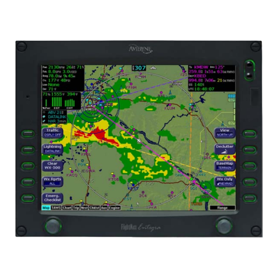
Page 104: Map Page With Datalink Weather
Map Page with Datalink Weather 11.2 Map Page with Datalink Weather The Map Page is the primary display for the Datalink weather information. Displayed on the Map Page are NEXRAD radar images, lightning strike information, AIRMETs/SIGMETs, graphical METAR symbols, and TFRs. Figure 11.1 Datalink Weather—Map Page 1) Sensor Status Block—The Sensor Status Block gives the status of the weather information presented. -
Page 105: Symbols Displayed Using Datalink
Using Datalink (Optional) 3) WX Rprts—Controls the type of Datalink weather information displayed on the map, as follows: ■ All—Displays graphical METARs, AIRMETs, and SIGMETs. ■ METARS—Displays graphical METARs only. ■ AIRMET—Displays graphical AIRMETs only. ■ SIGMET—Displays graphical SIGMETs only. ■... - Page 106 Map Page with Datalink Weather ● METAR symbols—Each METAR reporting station shown on the Map Page will have a METAR condition flag displayed. The color of the METAR flag indicates the current conditions at that airport: ● AIRMETs/SIGMETs—AIRMETs and SIGMETs are shown as ribbed lines enclosing the area of the advisory and are color coded and labeled as to their type.
-
Page 107: Using Datalink Without A Traffic Sensor
Using Datalink (Optional) ● TFR—Temporary Flight Restrictions (TFRs) are reported over Datalink. TFRs are shown with solid red lines on the Map Page. Note that at a full Map Declutter setting (all navigation data and airspace removed), TFRs will also be removed from the display. 11.2.2 Using Datalink without a Traffic Sensor Without a Traffic sensor installed, the EX5000 takes advantage of the available buttons and the WX Reports button is split into two buttons,... -
Page 108: Trip Page With Datalink Weather
Trip Page with Datalink Weather 11.3 Trip Page with Datalink Weather The EX5000 Trip Page also displays weather information from the weather Datalink. Each waypoint on the current active flight plan is associated with a METAR reporting point. For non-airport waypoints, the nearest METAR is used. - Page 109 Using Datalink (Optional) 3) Destination Airport Information—Provides quick access to airport information for the destination airport, when available. 4) Display—Controls the display in the bottom half of the Trip Page. Press Display to cycle between METAR, Legend, Status, Winds Aloft, and TAF data. For more detailed information, see Section 5.1, "Trip Page Information"...
-
Page 110: Nearest Page With Datalink Weather
Nearest Page with Datalink Weather 11.4 Nearest Page with Datalink Weather The EX5000 Nearest Page also displays METAR information received via Datalink. Similar to the Trip Page, the METAR symbols are displayed in a column next to the Nearest airports list, for all airports that have weather reporting stations. -
Page 111: Datalink Coverage
Using Datalink (Optional) 11.5 Datalink Coverage Weather data coverage from WSI or XM WX Satellite Weather includes the areas shown in Figure 11.5. Outside this area, weather information is not provided. The boundary of the coverage area is shown on the Map Page as a “hatched” pattern, as shown in Figure 11.6 on page 96. -
Page 112: Figure 11.6 Limits Of Datalink Coverage Area
Datalink Coverage Figure 11.6 Limits of Datalink Coverage Area 600-00108-000 Rev 07 -96- Entegra EX5000... -
Page 113: Using The Ex5000 Outside The Us
South America, call +1-303-799-9090, for eastern hemisphere, including Europe, call +49 6102 5070). ● Terrain Data—Avidyne provides terrain data for two areas: the Americas, and International (everything else). If you are flying in an area where your current terrain data is not supported, terrain will not display (similar to the Base view on the Map Page). - Page 114 MFD. An International Conversion Utility is available from Avidyne that changes the MFD terrain data between Americas and International. The utility can be installed in the field at an Avidyne Authorized Entegra Service Center. For information about the International Conversion Utility contact Avidyne Technical Support.
-
Page 115: Reference
13 Reference This section contains the following information: ● Updating Your Databases, page 100 ● Broadcast Datalink Service Purchase and Activation, page 106 ● ICleaning the EX5000 Screen, page 111 ● Sensor Status Block Symbols, page 112 ● Map Symbols, page 114 ●... -
Page 116: Updating Your Databases
Updating Your Databases 13.1 Updating Your Databases Avidyne makes use of three different types of data that can be uploaded to or downloaded from your EX5000: ● NavData—For the Map Page, Avidyne uses NavData from Jeppesen Sanderson, Inc. it is your duty as pilot in command to ensure that the data you fly with remains up to date. -
Page 117: Loading Navdata (The Navigation Database)
MFD. Unplugging the Zip Drive with the disk still engaged may cause damage to the disk. If using a USB Flash Memory: • Avidyne strongly suggests that, to avoid confusion, you reserve a USB Flash Memory Drive solely for EX5000 database transfers. - Page 118 Once you have downloaded the NavData from your PC to either a Zip Disk Dataloader or USB Flash Memory Drive, as described in the Avidyne Data Update Guide, you can upload the data to the EX5000. ➤ To load NavData to your EX5000: 1) Bring either the Zip Drive and disk or the USB Flash Memory Drive to the EX5000 at the aircraft.
-
Page 119: Loading Cmax Chart Data
Once you have downloaded the CMax data from your PC to either a Zip Disk Dataloader or USB Flash Memory Drive, as described in the Avidyne Data Update Guide, you will need to upload the data to your EX5000. ➤... -
Page 120: Downloading Emax Data
Updating Your Databases 6) At this point, turn off power to the EX5000, remove your USB Flash Memory Drive or Zip Drive, and then turn the EX5000 power back on. This step ensures that all data has been checked in self-test and the MFD is ready for use 7) Confirm the valid dates of the Chart data as reported on the Startup Screen. - Page 121 MFD is ready for use 9) You can now bring the Zip Drive or USB Flash Memory Drive to your PC and download the EMax data. See the Avidyne Data Update Guide for more information. Entegra EX5000...
-
Page 122: Broadcast Datalink Service Purchase And Activation
Broadcast Datalink Service Purchase and Activation 13.2 Broadcast Datalink Service Purchase and Activation To receive and display Broadcast Datalink weather and airspace, you must purchase service from WSI\Sirius or XM WX Satellite Weather. 13.2.1 Setting Up a Broadcast Datalink Account When you contact Sirius or XM Radio, they will request the following information: ●... -
Page 123: Setting Up A Wsi Broadcast Datalink Account
Reference 2) Activate WSI Broadcast Satellite Weather. 13.3.1 Setting up a WSI Broadcast Datalink Account If you have an MLB700 series Broadcast Datalink receiver installed, you must purchase service from www.myavidyne.com to activate the receiver. You will be required to provide the following: ●... -
Page 124: Using Sirius Audio
Broadcast activation is recorded by the Avidyne Network Operations Center (NOC). If 24 hours pass before you can get to your aircraft, contact Avidyne to have another test signal sent to your aircraft. The EX5000’s Service Level indication might take several... -
Page 125: Activating Sirius Audio
Broadcast receiver powered on for at least an hour. This ensures that the Broadcast activation is recorded by the Avidyne Network Operations Center (NOC). If 24 hours pass before you can get to your aircraft, contact XM Satellite Radio's Listener Care Center again or visit www.xmradio.com/activation... - Page 126 Using Sirius Audio The EX5000’s Service Level indication may take several Note: flights to synchronize to the correct level but you will still receive and see the weather products you have purchased. Contact Heads Up Technologies for problems relating to your Note: receiver or assistance with service.
-
Page 127: Icleaning The Ex5000 Screen
Reference 13.5 ICleaning the EX5000 Screen If your EX5000 screen should become dirty due to fingerprints or dust, clean the screen using the following materials and methods: ● A clean, soft lint free cloth such as 3M Ultra-Brite Cloth # 2011 or similar. -
Page 128: Sensor Status Block Symbols
Sensor Status Block Symbols 13.6 Sensor Status Block Symbols Table 13.1 Sensor Status Block Symbols Symbol Type Status Traffic A solid cyan symbol indicates that the sensor system is reporting a healthy Lightning status and is being displayed in the mode listed in the sensor status block. -
Page 129: Table 13.2 Broadcast Datalink Sensor Status Block (Optional)
Reference Table 13.2 Broadcast Datalink Sensor Status Block (Optional) Symbol Status A solid cyan arrow indicates that NEXRAD imagery is currently displaying on the Map Page, but the Broadcast signal is Marginal, Weak, or None. An animated black and cyan arrow indicates that NEXRAD imagery is turned off for display on the Map page, but the NEXRAD data is valid and the broadcast signal quality is Good. -
Page 130: Map Symbols
Map Symbols 13.7 Map Symbols The EX5000’s Map uses symbols contained in its navigational database, based on your navigational mode and flight situation. Map can display the following database items: ● Airports ● Navaids (VORs, NDBs and Waypoints) ● Airways (Victor and jet) ●... -
Page 131: Table 13.4 Map Symbols - Navigational Fixes
Reference Table 13.4 Map Symbols – Navigational Fixes Symbol Item Description All NDBs All VORs Intersection Terminal, Jet, and Victor airway waypoints (intersections) Table 13.5 Map Symbols – Traffic Symbols Non-TAS Type Meaning Symbol Symbol Traffic Alert (TA) Traffic within the alert zone defined by the traffic sensor. -
Page 132: Line Styles
Line Styles 13.8 Line Styles Table 13.7 Airspace and Airways Lines Item Color Line Label Class B Blue Elevation Class C Magenta Elevation Tower Zone Airspace Dashed Blue None Victor Airways Blue grey ID Label Jet Airways Blue grey ID Label Prohibited, Restricted ID Label Warning, Alert, MOA... -
Page 133: Data Blocks
Reference 13.9 Data Blocks Table 13.9 Data Block Information Name Description Range TO WPT Name of, bearing and distance to the “To” 5 characters waypoint in the active flight plan. The (Name) bearing is from your present position 1 to 360 degrees directly to the fix. -
Page 134: Table 13.10 Engine Instrument Data Block Information
Data Blocks Note: The Baro Altitude may be received from the FMS or GPS (via 429). The FMS/GPS calculates the altitude based on the barometric pressure entered into the FMS by the pilot and pressure altitude received from another source. This display verifies what has been put into the FMS/GPS. -
Page 135: Taws Messages
Reference 13.10 TAWS Messages Table 13.11 TAWS Messages TAWS Messages & Meaning Recommended Colors Pilot Action Caution Obstacle EGPWS Obstacle caution. Fly to avoid obstacle. Caution Terrain EGPWS Terrain caution. Fly to avoid terrain. OBSTACLE EGPWS Obstacle Warning. Pull up to avoid AHEAD, obstacle. - Page 136 EGPWS is not Page is painted with inhibited and if this magenta dots overlaid by the message persists, large text annunciation contact an Avidyne TAWS DISPLAY INHIBITED. Authorized Entegra Service Center. TAWS Display The EGPWS is unable to Check to see that...
-
Page 137: Nav Messages
Flight Plan will not be GPS/FMS and presented on the Radar installation display. Nav Source: Can't The GPS/FMS interface Have an Avidyne Open Port cannot open the assigned Authorized Entegra port. Generally indicates a Service Center check configuration error. configuration. - Page 138 Recommended Pi- NAV Messages Meaning lot Action and Colors Heading Data is GPS/FMS is configured as Have an Avidyne NOT Valid the Map heading source and Authorized Entegra that data ceases to be Service Center check available or becomes invalid.
-
Page 139: Traffic Messages
Traffic sensor is in self-test Acknowledge. Self-Test mode. Traffic Sensor is Traffic sensor is not Check that Traffic Not Communicating transmitting data. Sensor is on. Have configuration checked at an Avidyne Authorized Entegra Service Center. Entegra EX5000 -123- 600-00108-000 Rev 07... - Page 140 Traffic Messages Table 13.13 Traffic Messages (Continued) Traffic Messages Meaning Recommended & Colors Pilot Action TCAD Altitude TCAD sensor is not Have an Avidyne Unavailable receiving altitude Authorized Entegra information. Service Center check configuration. Traffic Heading TAS is configured as the...
-
Page 141: Lightning Messages
Lightning Sensor is Lightning source is in Have configuration in Noise- Monitor Noise- Monitor Mode. checked at an Avidyne Mode Authorized Entegra Service Center. Lightning Sensor is Lightning source is in Have configuration in Demo Mode Demo Mode. - Page 142 Recommended Pilot Messages & Colors Action Lightning Heading Stormscope is configured Have configuration Source Failed as a heading source and checked at an Avidyne a “fatal heading fault” is Authorized Entegra received. Service Center. Lightning Heading Stormscope is configured Acknowledge.
- Page 143 Recommended Pilot Messages & Colors Action Noise Present The TWX-670 has Have configuration (TWX-670 only) detected excessive check at an Avidyne noise in the system. Authorized Entegra Accuracy and Service Center. efficiency of the lightning sensor may be negatively affected.
-
Page 144: Engine Messages
Check that breaker is correctly Unit is Not data from Engine set. Communicating DAU or SIU. Have configuration checked at an Avidyne Authorized Entegra Service Center. Engine Sensor EX5000 receiving Have configuration checked at Unit Configuration invalid data from the... - Page 145 Reference Table 13.15 Engine Messages (Continued) Engine Messages Meaning Recommended Pilot & Colors Action Check Oil Press EX5000 has detected Acknowledge. Examine Oil (Not shown when an oil pressure Pressure on Engine Page. RPM > 1400) outside the normal Take corrective action and operating range.
- Page 146 Engine Messages Table 13.15 Engine Messages (Continued) Engine Messages Meaning Recommended Pilot & Colors Action Check Fuel EX5000 has detected Acknowledge. Examine the Remaining low remaining fuel. Fuel Remaining indicator on Yellow = Caution, Engine Page. Take corrective Red = Warning. action and land as soon as practical.
-
Page 147: Pfd Messages
PFD is operating in a Acknowledge. Normally normal state from a recoverable fault that was previously acknowledged. PFD is Not EX5000 is receiving Have configuration checked at Communicating no data from PFD an Avidyne Authorized Entegra Service Center. Entegra EX5000 -131- 600-00108-000 Rev 07... -
Page 148: Broadcast Datalink Messages
Broadcast Datalink Messages 13.15 Broadcast Datalink Messages Table 13.17 Broadcast Datalink Messages Datalink Messages Meaning Recommended Pilot & Colors Action Broadcast Receiver EX5000 has received no Have the wiring from Not Communicating data from the broadcast the broadcast receiver receiver for 10 minutes to the EX5000 inspected. - Page 149 Reference Table 13.17 Broadcast Datalink Messages (Continued) Datalink Messages Meaning Recommended Pilot & Colors Action Broadcast TAFs not The EX5000 did not Monitor Broadcast yet received receive TAF data within system during flight, the first 15 minutes after have system inspected power-on.
- Page 150 Broadcast Datalink Messages Table 13.17 Broadcast Datalink Messages (Continued) Datalink Messages Meaning Recommended Pilot & Colors Action Broadcast NEXRAD Broadcast NEXRAD data Monitor Broadcast > 120 min age since creation is system during flight, greater than 120 have system inspected minutes.
-
Page 151: Table 13.17 Broadcast Datalink Messages
Reference Table 13.17 Broadcast Datalink Messages (Continued) Datalink Messages Meaning Recommended Pilot & Colors Action Broadcast TAFs > 90 Broadcast TAF data age Monitor Broadcast since creation is greater system during flight, than 90 minutes. TAFs have system inspected will not display. if performance does not improve. -
Page 152: Abbreviations And Definitions
Abbreviations and Definitions 13.16 Abbreviations and Definitions The following avionics abbreviations and definitions are used in this manual: Table 13.18 Avionics Abbreviations and Definitions Abbreviation Meaning Above Ground Level Aeronautical Information Manual AIRMET AIRman's METeorological advisory Course Deviation Indicator CONUS Continental United States EGPWS Enhanced Ground Proximity Warning System... - Page 153 Reference Table 13.18 Avionics Abbreviations and Definitions (Continued) Abbreviation Meaning Temporary Flight Restrictions Universal Coordinated Time (Zulu)(Greenwich Mean Time) Visual Flight Rules Victor Airways Aerial highways that connect electronic navigation aids (more traffic). Victor Airways are 8 nautical miles wide (4 NM either side of the centerline) VHF Omnidirectional Radio Beacon Weather Entegra EX5000...
-
Page 154: Software License
Software, disk or related materials or create derivative works based upon the software or any part thereof. Title, ownership rights, and intellectual property rights in and to the Software belongs to Avidyne and its licensors. The Software is protected by the copyright laws of the United States and by international copyright treaties. - Page 155 If you do not agree to the terms of this license, Avidyne is unwilling to license the product to you. In such event, you may not use or copy the product, and you should promptly contact Avidyne for instructions on return of the unused product(s) for a refund.
- Page 156 FAX:781-402-7599 www.avidyne.com P/N 600-00108-000 Rev 07 08/08 © 2007 Avidyne Corporation All Rights Reserved. Avidyne ® , FlightMax ®, CMax ™ , and EMax ™ are trademarks of Avidyne Corp. ® ® SKYWATCH and STORMSCOPE are trademarks of L-3 Corp.
Need help?
Do you have a question about the Entegra EX5000C and is the answer not in the manual?
Questions and answers