
Subscribe to Our Youtube Channel
Related Manuals for Mircom FX-2200 Series


Summary of Contents for Mircom FX-2200 Series
- Page 1 Advanced Life Safety Solutions FX-2200 Series Fire Alarm Control Panel LT-2002MIR Rev. 0 Operator’s Manual November 2006...
-
Page 2: Table Of Contents
FX-2200 Operator’s Manual Contents 1.0 Unit Operation ............................1 1.1 Power Up Sequence ........................1 1.2 Types of Inputs ..........................1 1.3 Status Display ..........................2 1.4 Zone LEDs ............................. 2 1.5 Buzzer ............................2 1.6 Operator Keys ..........................3 1.7 Alarm List ............................ -
Page 3: Unit Operation
FX-2200 Operator’s Manual 1.0 Unit Operation 1.1 Power Up Sequence The power up sequence of the FX-2200 Fire Alarm Control Panel (hereafter referred to as the FX- 2200) panel is started in the following ways: power is applied to the panel; the hard reboot button at the top of the main board is pressed;... -
Page 4: Status Display
FX-2200 Operator’s Manual 1.3 Status Display The status display is located in the middle of the main display. It consists of 8 LEDs. The alarm (red), supervisory (yellow), trouble (yellow), ground fault (yellow), and NAC trouble (yellow) LEDs will flash for any new condition and will be latched by the Acknowledge key. The AC LED (green) will be on while the panel has AC power applied to it. -
Page 5: Operator Keys
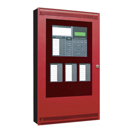
FX-2200 Operator’s Manual 1.6 Operator Keys There are 8 operator keys. In the figure below, the keys are located on the lower left and are labelled “System Controls” The LEDs associated with these keys are used to display function status. The top three keys (Acknowledge, Signal Silence, and System Reset) are not user- assignable. - Page 6 FX-2200 Operator’s Manual Action System System Reset resets part or all of the system. Reset • The rightmost green LED flashes when the system, or part of the system, can be reset. • The leftmost green LED flashes if the ground fault relay is activated. Press System Reset to deactivate the ground fault relay to check for restores and additional ground faults.
-
Page 7: Alarm List
FX-2200 Operator’s Manual Action Common This function is configurable. It can be programmed to disable the relays or to Disconnect disable a City Tie module (PR-2200). When an PR-2200 module is disconnected, a trouble will be reported to the city and then any subsequent signals will not be reported until the card is re-enabled. -
Page 8: Lcd And Keypad
FX-2200 Operator’s Manual the First or Last entry. Once viewing the events, one can look at the next one using the <Right Arrow> or the previous one with the <Left Arrow>. <Enter> will act as either <Left Arrow> or <Right Arrow>, whichever was pressed last. <Up Arrow> and <Down Arrow> will rotate between pages of the event. - Page 9 FX-2200 Operator’s Manual The Main Menu has the following selections: Status: Displays the current status of various parts of the panel. The following options are available: More: Displays the next screen of menu options. When the last screen of the menu is displayed the next screen will be the first one again.
- Page 10 FX-2200 Operator’s Manual of occurrence for events occurring at or to the panel. There may be a second screen including information from the database. You can start by looking at either the last event (newest) or the first event (oldest). When viewing the events, scroll to the next one using the <Right Arrow> or the previous one with the <Left Arrow>.
-
Page 11: Supplementary Information
FX-2200 Operator’s Manual 2.0 Supplementary Information 2.1 Condition Codes and Zone Numbers The History and Archive use the following formats for condition codes and zone numbering. Condition Code Archive Alarm List Description ALARM Alarm bypass Bypass Comlink dupl Duplicate Addressable Device alert Maintenance Alert ground... - Page 12 FX-2200 Operator’s Manual Notes: 1. These zones do not restore. 2. Privilege Level 0 generates a restore signal; all others generate a trouble signal. 3. This zone does not restore and is not repeated sequentially in the archive. Sub-Zone Number Addressable Circuit: Device Number Comlink 1 (Zone 51): Unit Netowork ID number Comlink 3 (Zone 53): Unit ID number...
-
Page 13: Miscellaneous Troubles
FX-2200 Operator’s Manual 2.2 Miscellaneous Troubles This is a list of all possible messages that can be displayed by Miscellaneous Trouble on the LCD. Only those conditions that are in trouble will be shown. Some of the messages are always displayed if the panel is in Test Mode. - Page 14 FX-2200 Operator’s Manual Message Description List the status of the 8 bell circuits and the 2 auxiliary power circuits. BBBBBBAA Each column represents one circuit. A dot (.) indicates a normal 1234567812 condition, an S indicates a short, an O indicates an open and a G indicates a ground.
- Page 15 The extended memory lockout has timed out. The panel will need a memory lockout Hard Reboot to correct this problem. Please notify Mircom of the occurrence of this error. Include in your report the panel serial number and the name, date and time of the operating program.
- Page 16 Advanced Life Safety Solutions Canada U.S.A. © Mircom 2006 Printed in Canada 25 Interchange Way 60 Industrial Parkway PMB 278 Subject to change without prior notice Vaughan, ON L4K 5W3 Cheektowaga, NY 14227 Tel: 1-888-660-4655 Fax: 1-888-660-4113 www.mircom.com Tel: 905-660-4655 Fax: 905-660-4113...
Need help?
Do you have a question about the FX-2200 Series and is the answer not in the manual?
Questions and answers