
Related Manuals for Mircom FX-401


Summary of Contents for Mircom FX-401
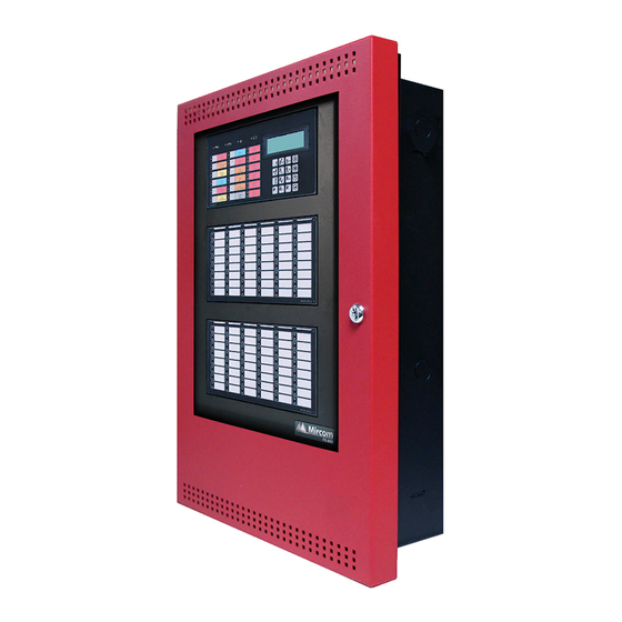
- Page 1 FX-401 Fire Alarm Control Panel LT-6670 Rev 1 Installation and Operation Manual October 2021...
-
Page 3: Table Of Contents
Industry Canada Notice ....................Notice for all FX-400 Series Built-in UDACTs Sold in the U.S.A........FCC Notice ........................Introduction The FX-401 Addressable Fire Alarm Control Panel ............FX-401 Overview FX-401 Fire Alarm Control Panel Model ................ FX-401 System Components .................. - Page 4 Security Industries Association SIA Format Protocol FX-400 Series Event Codes ..11.0 Appendix D - Specifications And Features 11.1 FX-401 Fire Alarm Control Panel ................... 11.2 FX-401 System Module and Annunciator Specifications ..........12.0 Appendix E - Battery Calculations 13.0 Warranty and Warning Information...
- Page 5 Figure 20 TS1 SPECIAL APPLICATION Power Source Wiring ............. Figure 21 Wiring the Dialer ......................Figure 22 Connecting an FX-401 FACP to a 3G4010 Interface Device in Canada ....... Figure 23 Connecting a FACP to a 3G4010CF Interface Device outside Canada ......
- Page 6 Power Supply Electrical Ratings ..................Table 18 Compatible DACR Receivers ..................Table 19 Contact-ID Event Codes ....................Table 20 SIA-DCS Event Codes ....................Table 21 FX-401 Specifications ....................Table 22 FX-401 Modules and Annunciator Specifications ............Table 23 Recommended Batteries ....................
-
Page 7: Industry Canada And Fcc Notice
Industry Canada and FCC Notice Notice for all FX-400 Series Built-In UDACTs Sold in Canada Mircom's FX-400 SERIES BUILT-IN UDACT Communicator described in this manual is listed by Underwriters Laboratories Canada (ULC) for use in slave application under Standard ULC- S527 (Standard for Control Units for Fire Alarm Systems) and ULC-S559 (Equipment for Fire Signal Receiving Centres and Systems). -
Page 8: Fcc Notice
In the event repairs are ever needed on the Communicator, they should be performed by Mircom Technologies Ltd. or an authorized representative of Mircom Technologies Ltd. For information contact Mircom Technologies Ltd. -
Page 9: Introduction
Introduction This document provides information for the successful installation and operation of the FX-401 Fire Alarm Control Panel (FACP). The FX-401 Addressable Fire Alarm Control Panel Mircom's FX-401 Addressable Fire Alarm Control Panel provides the following: • MGC Protocol with up to three addressable (SLC) loops with a maximum of 720 MGC devices (MIX-4000 series), 240 per loop. - Page 10 RAX-1048TZDS (up to 96 points) and to facilitate the indication of bypass points. Display Points The FX-401 LCD display annunciates the status of the system and connected devices. There are up to two (2) RAX-1048TZDS Display Adder Module Display points that may be configured to assign LEDs to groups of inputs or outputs.
-
Page 11: Fx-401 Overview
FX-401 Overview This chapter lists all the possible components of an FX-401 system. FX-401 Fire Alarm Control Panel Model The FX-401 Fire Alarm Control Panel has the following features: • Main Board, Power Supply and Backbox. • Multi-zone fire alarm control panel •... -
Page 12: Fx-401 System Components
FX-401 System Components The following table describes the components of the FX-401. Table 1 FX-401 System Components Model Description Model FX-401, black backbox, red door enclosure FX-401 comes complete with main board, power supply, transformer and main display. MAM-3500 Main Display... - Page 13 Table 1 FX-401 System Components (Continued) Model Description RAM-3500-LCD Remote Annunciator with 4-line LCD Display. PR-300 Polarity Reversal and City Tie Module. Power Supply Interface Board use for powering PCS-100 3G4010 or 3G4010CF Universal Wireless Alarm Communicator. Smart Relay Module with White Enclosure.
- Page 14 Table 1 FX-401 System Components (Continued) Model Description 48 Point adder annunciator display with 48 Trouble RAX-1048TZDS LEDs. MGD-32 Graphic Annunciator. RAX-LCD-LITE Remote Annunciator with 4-line LCD Display. AGD-048 Graphic Annunciator Adder Driver Board. Common Remote Trouble Indicator, Buzzer and RTI-1 LED.
- Page 15 Table 1 FX-401 System Components (Continued) Model Description BB-1002D White Enclosure for two annunciators. BB-1002DR Red Enclosure for two annunciators. BB-1002DS Enclosure for two annunciators with stainless steel door. BB-1002WPA White enclosure for two annunciators rated for outdoor environment, wet location.
-
Page 16: Table 2 Mix-4000 Mgc Addressable Devices
3.2.1 Devices The following tables lists all the devices available for the FX-401. Table 2 MIX-4000 MGC Addressable Devices MGC Addressable Detectors and Control Modules MGC Addressable Detectors MIX-4010 Photoelectric Smoke Sensor MIX-4010-ISO Photoelectric Smoke Sensor with Built-in Short Circuit Isolator... -
Page 17: Installation
Installation This chapter describes the installation of the FX-401. UB-1024DS Mechanical Installation The UB-1024DS is a black backbox suitable for flush or surface mounting with a built-in trim ring. The DOX-1024DS is the front door of this backbox, which is available in white and red, DOX-1024DSR. -
Page 18: Installation Tips
Installation Tips 1. Group the incoming wires through the top of the enclosure. For easy identification and neatness use a wire tie to group wires. 2. Be sure to connect a solid Earth Ground (from building system ground / to a cold water pipe) to the Chassis Earth Ground Mounting Lug, and to connect the Earth Ground Wire Lugs from the Main Chassis to the ground screw on the Backbox. -
Page 19: Connections And Jumpers
Connections and Jumpers JW11 Main Board JW10 Core Board Buzzer JW12 JW14 Figure 3 Port and Jumper Locations on Main Board... -
Page 20: Table 3 Main Board Connectors And Jumpers
Table 3 Main Board Connectors and Jumpers Connector/ Description Jumper To Power Supply To Power Supply Ribbon Cable connects to P4 of front display To PC Configurator Factory Use Only To PR-300 To Printer To ALC-480 Loop Adder Factory Use Only USB Port to PC Configurator Future Use Must be ON (default) - Allows Configuration Connection... -
Page 21: Installing Adder Modules
Figure 4 Jumper on back of display Installing Adder Modules The FX-401 Fire Alarm panels are shipped pre-assembled with all main components and boards. Adder modules are not pre-installed. The following items can be installed in the field: •... -
Page 22: Figure 5 Main Board With All Adder Modules Installed
See the following diagrams for adder module installation locations. For Jumper or DIP Switch settings refer to Table 3 and for Wiring Specifications see 7.1 Wiring Tables. TR-063A Transformer Barrier Terminal Block FX-401 Main Board Rectifier Bridge ALC-480 Dual Loop Adder MD-1011 Power Supply Board... -
Page 23: Figure 6 Installing The Pr-300 Polarity Reversal And City Tie Module
Table 5 PR-300 Polarity Reversal and City Tie Module Connectors and Jumpers Item Setting Connect cable to P8 on the Main Board of the FX-401 Not used. Keep jumper intact. Note: If using a PR-300 remember to remove JW7 on the main board. For the location... -
Page 24: Installing The Alc-480 Dual Loop Adder
Connect cable to P10 on the Main Board of the FX-401. 4.5.1 Installing the RAX-1048TZDS Display Adder Module The FX-401 can have a maximum of two RAX-1048TZDS Display Adder Module. No jumpers or other physical configuration steps are required to install the RAX-1048TZDS Display Adder Modules. -
Page 25: Operation
Test Signal for Dialler 6, 12, 24 hours 6 hours maximum Addressable/Analog Devices The FX-401 System supports up to 3 loops with a total of 720 MGC addressable devices. Configuration is done via the MGC-400 software configurator. Additional Information •... -
Page 26: Figure 8 Mgc-400 Configurator Date And Time Settings
5.1.1 Supervision of Devices The loop interface software continuously supervises the devices on its loop against those found during configuration for the following conditions: • Device missing. • Unconfigured device responding. • Two or more devices responding to the same address. •... -
Page 27: Configurable Input Types
The panel can provide up to 280mA of current to the devices on the loop at normal standby. For device currents see Appendix E - Battery Calculations on page 86. For further information refer to the device Installation Instructions and other documentation provided with the addressable devices, bases, and isolators. - Page 28 Table 9 Configurable Input Types (Continued) Device Types Dual Input Module Description Mini Dual Input Module As listed in located in Conventional Zone Input Type Configurator Section number Detectors Module Buzzer Silence Buzz Sil 5.2.7 Signal Silence Signal Silence 5.2.7 Acknowledge General Ack GA 5.2.7...
- Page 29 • Supervisory input activations display as the second highest priority on the shared display in the common queue. • Devices configured as supervisory inputs display as supervisory conditions on the shared display and on the supervisory zone status indicator. • Restoring the non-latching supervisory input returns all outputs correlated to the input, that are not correlated to another active input, to normal.
- Page 30 • May also be programmed to relay, signal, and strobe outputs. Note: Trouble conditions initiated as a result of a trouble-only input activating is separate from the circuit or device supervision trouble. 5.2.6 Waterflow Alarm Input Waterflow inputs are sampled every second. 10 samples in alarm in any given 15 second period confirms the alarm condition.
-
Page 31: Output Types
5.2.10 Manual Day/Night Configures (mini) dual input modules for manual day/night alarm thresholds. For more information on alarm thresholds see 5.1.3 Alarm Conditions. 5.2.11 Auto Day/Night Configures (mini) dual input modules for auto day/night alarm thresholds. For more information on alarm thresholds see 5.1.3 Alarm Conditions. 5.2.12 Verified Alarm Input Un-bypassed verified alarm inputs entering into alarm are verified over a period of time to... -
Page 32: Table 10 Configurable Output Types
Synchronized strobes and strobe/horn models of the following manufacturers are supported: Mircom, System Sensor, Wheelock and Gentex. Note: Silencing of the horn depends on the feature provided by the manufacturer of the horn/strobe combination. -
Page 33: Nac Circuit Operation
The trouble condition will be re-evaluated when supervision resumes. Output circuits configured as strobes can have sync protocol for synchronization if configured. Certain strobe and strobe/horns models of the following brands are supported: • Mircom • System Sensor • Wheelock •... -
Page 34: Two-Stage Operation
• Activates non-disconnected strobes associated with the input. • Activates non-disconnected signals associated with the input at the evacuation rate. Subsequent alarms when the panel is already in alarm, cause the following: • The alert buzzer sounds steady. • Resounds silenced signals, turns off the Signal Silence LED, and restarts the Auto Signal Silence timer (if configured). -
Page 35: Evacuation Codes
5 seconds on 10 seconds off. 5.7.1 Two Stage Alert Code When configured for Two Stage operation, the FX-401 FACP uses a pre-configured Alert code that sounds prior to the evacuation code. Alert Code 0.5 second on, 2.5 seconds off. - Page 36 Any of these alarm inputs activating when the panel is not already in alarm causes the following: • Buzzer sounds steady. • Cancels active fire drill. • Common Alarm LED turns ON. • Individual zone LED (if programmed) turns ON. •...
-
Page 37: Remote Annunciator Operation
1. In the Job Details window, check the Positive Alarm Sequence box. This option only applies to alarm input devices with the PA flag (F2) set. Remote Annunciator Operation The FX-401 System supports the following types of annunciators (Class B) • RAX-LCD-LITE shared display annunciator. - Page 38 5.9.4 Conventional Annunciators The FX-401 System is designed to interface with the RA-1000 series of conventional LED annunciators. The LEDs may be configured to zone status indicators. Each conventional annunciator contains a local alert buzzer. Under normal operation the alert buzzer is controlled by the system and operates in an identical manner as the one in the main panel.
-
Page 39: Dialer Operation
5.10 Dialer Operation The FX-401 is equipped with a built-in dialer. The dialer provides a means to communicate panel status to the remote central monitoring station using two dedicated phone lines. The two standard protocols for communicating with the central monitoring station are supported by this panel are as follows. -
Page 40: Figure 10 Operation Menu
• Clearing Logs • Walk Test Function • Bypass Operation • Disconnecting Auxiliary Relays • Testing the Dialer • After Hours Operation • Clearing Verification Counts • Ground Fault Testing - Factory Use Only Complete configuration of the system is done via the software configurator. How to Enter the Operation Menu 1. - Page 41 5.11.2 Setting the Password By default, no password is required to press the control buttons and enter the operation menu. Sets the password for all three access levels. The minimum number of digits for a password is 4. For changing a specific level of password the password required is the equivalent level or higher level.
- Page 42 • Activation of any alarm input or common control which activates the common alarm sequence. • Activation of system reset. • Clearing of the event log (as the first entry). Each entry contains the time and date of the event and a description of what the event was, for example: Nverf alm ipt Active...
- Page 43 The display shows the loop number, device address, the device type, device status, and the level of alarm, in the following format: Loop 1 Address 2 0001 0000 0096 0032 (0% alarm) 2. Press the Up and Down cursor keys to scroll through all the devices on the loop. 3.
- Page 44 MP devices. Since parameter values and addresses are not disclosed to the user, this tool is used to report information to Mircom technical support. If the panel is connected to a printer the user will be prompted to select an output source: - Report To - 1.
- Page 45 5.11.4 Clear Logs Clears the logs stored in the flash memory. Press the Up and Down cursor keys to the desired log to be cleared and press the Enter button. Select Log 1. Alarm Log 2. General Log 3. All Logs A message prompts for confirmation.
- Page 46 While the walk-test is active the following message is displayed on the screen: - Walktest Active - Alarms: nnn Troubles: mmm Press ENTER to end where nnn and mmm are continuously updated counts of the number of alarms and troubles which have been recorded during the test (alarms includes all input circuit types tested).
- Page 47 After the confirmation, the device is bypassed and the message appears that the device is bypassed. Device /circuit Bypassed If the device is already bypassed the user is prompted to un-bypass the circuit. Device now bypassed Unbypass ?Y/N After the confirmation, the device is un-bypassed and the information message shows that the device is un-bypassed.
-
Page 48: Table 12 List Bypass Special Characters
Loop number Loop :__ If the loop is not already bypassed the user is then prompted to bypass the loop. Loop 0 not bypassed Bypass ?Y/N After the confirmation, the loop is bypassed and a bypass confirmation message displays. Loop Bypassed If the loop is already bypassed, the user is prompted to un-bypass the loop. - Page 49 The following message is displayed to bypass. If the device is already bypassed the message is as follows. If the exclamation is not used, then there will be individual confirmation. At the end of the bypass operation or if the exclamation is used, the message displays: 5.
- Page 50 5.11.7 Auxiliary Disconnect The auxiliary disconnect operation is performed by the following the steps below. If the auxiliary relays are connected the user is prompted to disconnect the relays. Aux relays connected Disconnect ?Y/N After the confirmation the auxiliary relays are disconnected and the information message is displayed that the auxiliary relays are disconnected.
- Page 51 Day/night mode updated 5.11.10 Clear Verify Count This operation is used to clear all the verification counts accumulated during the alarm verification process. The user is prompted for confirmation as shown below: Clear all verif Counters ?Y/N After the confirmation the verification count is cleared and the information message is displayed that the counts are cleared.
-
Page 52: Indication & Controls
• 12 Control buttons with associated LEDs • 16 button Numeric Keypad with Cursor buttons Figure 11 displays the LED indicators and the control button on the FX-401 main board. Visual Indicator Test Figure 11 LED Indicators and Control Buttons The FX-401 has the ability for 2 additional RAX-1048TZDS. -
Page 53: Figure 12 Numeric Keypad
6.2.1 Numeric Keypad and Cursor Buttons Figure 12 Numeric Keypad Description Key 2 (Up cursor) Press this button to move the cursor or scroll up lists in a continuous loop. Key 4 (Left Cursor) Press this button to move the cursor or select options to the left. Key 6 (Right Cursor) Press this button to move the cursor or select options to the right. -
Page 54: Common Led Indicators And Control Buttons
Common LED Indicators and Control Buttons For complete descriptions of all LED indicators and control buttons see the following table. Table 13 LED Indicators and Control Buttons LED Indicator and Description Control Buttons AC On Indicator Illuminates steady green when the main AC power is within acceptable levels. The LED turns off when the level falls below the power-fail threshold and the panel is switched to standby (battery) power. - Page 55 Table 13 LED Indicators and Control Buttons (Continued) LED Indicator and Description Control Buttons Trouble Queue Button and Indicator Flashes yellow when any trouble condition is detected on the panel. The buzzer sounds at the slow rate. Pressing the Trouble Queue button allows the user to cycle through and review a list of active Troubles from oldest to most recent.
- Page 56 Table 13 LED Indicators and Control Buttons (Continued) LED Indicator and Description Control Buttons Automatic Alarm Signal Cancel Button and Indicator - Two Stage Automatic Alarm Operation Only Signal Cancel LED and Indicator are active only when the Panel is configured for Two Stage Operation.
- Page 57 Table 13 LED Indicators and Control Buttons (Continued) LED Indicator and Description Control Buttons Auxiliary Disconnect Button and Indicator Activating the Auxiliary Disconnect button activates the Auxiliary Disconnect function. The Auxiliary Alarm Relay is always disconnected with this button. The Common Alarm Relay, the Common Supervisory relay and all correlated alarm relays may be disconnected as selected through configuration.
-
Page 58: Wiring
Wiring This chapter describes the proper field wiring for the FX-401. Wiring Tables 7.1.1 Addressable Loop Wiring Maximums MGC Devices • Maximum Loop Current = 350 mA • Maximum Loop Resistance = 40 ohms • Maximum Loop Capacitance = 0.5 F •... -
Page 59: Table 15 Nac And Auxiliary Power Circuits Wiring Table
Maximum Voltage Drop Should Not Exceed 1.67 Volts 7.1.4 Input Circuits If using conventional detectors with an FX-401 FACP, MIX-4042 conventional zone modules must be used. Refer to document LT-1023 for compatible devices. Table 16 Conventional Zone Module Input Circuit Wiring Table... -
Page 60: Wire Routing
Wire Routing Notes: All external connections are power limited except for the AC connections to the transformer. Transformer connections must be routed separately from all other external connections using their own conduit. All power limited wiring shall be routed through the remaining knockouts. -
Page 61: Addressable Loop Wiring
Addressable Loop Wiring Note: When an SLC device is powered by the AUX output, the supervision of the power pathway shall match the SLC pathway performance requirements. 7.3.1 Addressable Loop Wiring - Class B (DCLB) MULTI-SENSOR DETECTOR OUTPUT MODULE PHOTOELECTRIC SMOKE SENSOR PULL STATION TRI-MODE HEAT DETECTOR... -
Page 62: Nac Circuit Wiring
SENSOR M500X ISOLATOR TRI-MODE HEAT DETECTOR Figure 16 Addressable Loop Wiring - Class X (DCLC) NAC Circuit Wiring The FX-401 supports up to 4 NAC circuits that can be wired as either: • Class B • Class A To supervise each Class B NAC circuit, use a 3.9K End-of-Line resistor. -
Page 63: Figure 17 Nac Circuit - Class B Wiring
7.4.1 NAC Circuit – Class B Wiring CIRCUIT - 1 + + - - NAC1 NAC CIRCUITS #2, #3 AND #4 ARE NOT SHOWN. WIRE AS SHOWN ABOVE. BELL STROBE HORN EOL-392 Figure 17 NAC Circuit – Class B Wiring 7.4.2 NAC Circuit –... -
Page 64: Figure 19 Rti-1 Common Remote Trouble Indicator Wiring
7.4.3 UL 864 Rev. 10 Addressable Supervised Output Module Wiring As per UL864 Rev.10 56.4.3, ensure that a single break, ground or wire-to-wire fault on the installation conductors of a signalling circuit for use with addressable notification appliances or modules shall not affect the operation of more than one notification zone. Exception: Riser conductors installed in accordance with the survivability from attack by fire requirements in National Fire Alarm Code, NFPA 72. -
Page 65: Ts1 Special Application Power Source
TS1 SPECIAL APPLICATION Power Source The TS1 SPECIAL APPLICATION power source is located on the bottom right side of the power board (below the transformer and AC wiring). SLC LOOP WIRE MIX-4040 DUAL INPUT MODULE SLC+ SLC- SLC+ − SLC- POWER LINE 24 VDC −... -
Page 66: Module And Devices Wiring
Module and Devices Wiring 7.6.1 Dialer Wiring Wire the Dialer to the Public Telephone Switch and premises Telephone as shown in Figure 21. For information on Compatible DACR Receivers see Appendix A - Compatible Receivers on page 76. Public Switch Telephone Wiring RJ31X GREEN BROWN... -
Page 67: Figure 22 Connecting An Fx-401 Facp To A 3G4010 Interface Device In Canada
Default Gateway : X.X.X.X radio trouble Sub-Net Mask:X.X.X.X Port #: YYYY (UDP) Figure 22 Connecting an FX-401 FACP to a 3G4010 Interface Device in Canada Note: The DSC interface device 3G4010 is required if the installation requires ULC S559 certification. -
Page 68: Figure 23 Connecting A Facp To A 3G4010Cf Interface Device Outside Canada
A typical connection is shown in Figure 24. The 3G4010CF is powered separately from the PCS-100 and requires 2 DSC RM-2 relays (sold separately). The PCS-100 Passive Communications Interface Board (sold separately) is also required. FX-401 - 3G4010CF Connection - Typical Diagram Telephone Line A... -
Page 69: Figure 24 Connecting A Facp To A Sle-Ltev Or Sle-Ltea Interface Device Outside Canada
A typical connection is shown in Figure 24. The SLE-LTEV or SLE-LTEA is powered separately from the PCS-100. The PCS-100 Passive Communications Interface Board (sold separately) is also required. FX-401 - NAPCO STARLINK SLE-LTEV Connection - Typical Diagram Telephone Line A... -
Page 70: Figure 25 Wiring The Pr-300 Polarity Reversal And City Tie Module
7.6.5 PR-300 Polarity Reversal and City Tie Module Wiring Wire the PR-300 Polarity Reversal and City Tie Module successfully as shown in Figure 25. • Plug PR-300 ribbon cable P1 into connector P8 on the Main Fire Alarm Board. • Remove jumper plug from JW7 on the Main Fire Alarm Board. -
Page 71: Power Supply Wiring
600 volt insulation and proper over current circuit protection that complies with local codes. For FX-401 Power Supply Electrical Ratings see Table 17 Power Supply Electrical Ratings and for Specifications see 11.0 Appendix D - Specifications And Features. -
Page 72: Figure 26 Main Power Supply Wiring And Connections
White/Blue Stripe Blue Black Brown FX-401 Main Board 240VAC 50Hz 120VAC 60Hz Ribbon Cable Ground Green Black Power Connector – BRIDGE MD-1011 Power Supply Board P5 P6 BLACK BLACK BATTERY BATTERY Figure 26 Main Power Supply Wiring and Connections 7.7.2... -
Page 73: Figure 27 Supervision Of Auxiliary Supplies
This filtered circuit is supervised for shorts. A short will: • Disconnect the power until the “RESET” button is pressed. • Generate a trouble signal The circuit must be supervised for opens utilizing the End of Line Relay Model EOLR-1(A) as shown in Figure 15. -
Page 74: Placement Of Ferrites For Fcc Standard
7.8.2 ALC-480 Dual Loop Adder Module If an ALC-480 Dual Loop Adder Module is used with the FX-401, one ferrite is required for each loop. The two ferrites are packed with the ALC-480. Place the wires coming out of Loop 1 through the ferrite and loop around the ferrite once and back out to connect to devices. -
Page 75: System Checkout
System Checkout The following are the recommended steps before and during the powering up of the FX-401. 7.9.1 Before Turning The Power ON 1. To prevent sparking, DO NOT connect the batteries first. Connecting the batteries is only to be done after the system has been powered from the main AC Supply. -
Page 76: Appendix A - Compatible Receivers
Appendix A - Compatible Receivers The dialers that are built into select models of the FX-401 Fire Alarm Control Panels are compatible with the following Digital Alarm Communicator Receivers (DACR) listed: Table 18 Compatible DACR Receivers DACR Receiver Model Protocols... -
Page 77: Appendix B - Manual Panel Configuration
Appendix B - Manual Panel Configuration COMMAND MENU The command menu is the first menu displayed for command mode. The command menu is divided into four main sub menu categories, the configuration allows full front panel configuration of the system and the operation menu performs certain operations which may not be possible using the common control switches and indicators on the front panel. - Page 78 Panel Configuration/Features/Waterflow Retard Waterflow retard [ ] Enabled If disabled, all the initiating circuits configured as waterflow act as non-verified alarms. If enabled, retard operation is performed for initiating circuits configured as waterflow. Panel Configuration/Features/Auxiliary disconnect, disconnects alarm and supervisory relay Aux Dis Alm&Sv [ ] Enabled If enabled the auxiliary disconnect operation, disconnects alarm and supervisory relays disabled the...
- Page 79 ON steady. This feature applies to the main panel powered output circuits, configured as strobes, only. Note: Once a specific type of strobe is selected, for example Mircom, then only this type of strobe is allowed for the entire system. Panel Configuration/Features/Evacuation code Evac.
- Page 80 Panel Configuration/Features/Class-A loop Loop ClassA [ ] Enabled This feature configures all addressable loops as Class A if enabled. Panel Configuration/Features/Auto after hours Auto afthrs. [ ] Enabled This feature allows the daytime/nighttime mode to be set automatically if enabled. Panel Configuration/Features/General alarm timer Gen.alm tmr [x] Disabled...
- Page 81 PANEL CONFIGURATION/4. USER MESSAGE Allows you to edit (change) the FACP Front Panel Message, i.e. “Welcome to Mircom”. PANEL CONFIGURATION/5. LANGUAGE Allows you to select the language of the LCD display. English is the default. To change the language to French, select French in the panel configuration menu, then exit the configuration and then re-enter and select auto default.
-
Page 82: Appendix C - Reporting
10.0 Appendix C - Reporting 10.1 Ademco Contact-ID FX-400 Series Event Codes Table 19 Contact-ID Event Codes Event Description Event Qualifier Code Group # Contact # Family Phone Line #1 trouble detected Trouble New event 1 351 Phone Line #2 trouble detected Trouble New event 1 352... -
Page 83: Security Industries Association Sia Format Protocol Fx-400 Series Event Codes
10.2 Security Industries Association SIA Format Protocol FX-400 Series Event Codes SIA Format Protocol does not define indicating zone troubles, but lists it as Untyped Zone Trouble/Restore. Table 20 SIA-DCS Event Codes Event Description Event Family Qualifier SIA Event Code Parameter Phone Line #1 trouble detected Trouble New event... -
Page 84: Appendix D - Specifications And Features
Appendix D - Specifications And Features 11.1 FX-401 Fire Alarm Control Panel Table 21 lists specifications for the FX-401 panel: Table 21 FX-401 Specifications FX-401 Fire Alarm Control Panel General Digital signal processor based design, fully configurable from front panel with... -
Page 85: Fx-401 System Module And Annunciator Specifications
NFPA 70, 72, CAN/ULC-S559-13, UL-864 Rev. 10, ULC S524, CAN/ULC-S527-11 Standards and ULC-S536-04 11.2 FX-401 System Module and Annunciator Specifications Table 22 FX-401 Modules and Annunciator Specifications FX-401 System Modules and Annunciators RAM-3500-LCD Remote Annunciator Standby 70mA / alarm 100mA... -
Page 86: Appendix E - Battery Calculations
For specifications see Appendix D - Specifications And Features. Power Requirements (All currents are in amperes) Total Total Model Number Description Standby Alarm Standby Alarm FX-401 FX-401 FACP with Dialer 0.390 0.630 ALC-480 480 Point Dual Loop Adder 0.120 0.200 Remote Annunciator with 4- RAM-3500-LCD 0.070 0.100... -
Page 87: Table 23 Recommended Batteries
Total Alarm Current must be 10 amperes or less. NAC Circuits must not exceed 6 amperes. Battery Selection Battery Size = Multiply (C) by 1.20 to derate battery. See the following table for the recommended Mircom batteries for use with this panel Table 23 Recommended Batteries Battery Model... -
Page 88: Warranty And Warning Information
As the only individual in contact with system users, please bring each item in this warning to the attention of the users of this Mircom System. Failure to properly inform system end-users of the circumstances in which the system might fail may result in over-reliance upon the system. - Page 89 11. Battery Failure. If the Mircom System or any device connected to the system operates from batteries it is possible for the batteries to fail. Even if the batteries have not failed, they must be fully charged, in good condition, and installed correctly.
- Page 90 20. Integrated Products. Mircom System might not function as intended if it is connected to a non-Mircom product or to a Mircom product that is deemed non-compatible with a particular Mircom System.
- Page 91 CANADA - Main Office U.S.A © Mircom 2021 25 Interchange Way 4575 Witmer Industrial Estates Printed in Canada Vaughan, ON L4K 5W3 Subject to change without prior notice Niagara Falls, NY 14305 Tel: (905) 660-4655 Tel: (905) 660-4655 www.mircom.com (888) 660-4655...
Need help?
Do you have a question about the FX-401 and is the answer not in the manual?
Questions and answers