Advertisement
Quick Links
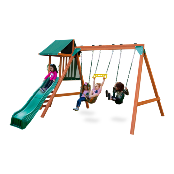
PB 8370
PB 8370 INCLUDED WITH PB 8375 model.
PB 8360 SWING BAY
WITH SWINGS SOLD
SEPARATELY.
This ADD-ON is only to be used with
PB 8360 Swing Bay
Swing-N-Slide • 166 Etowah Industrial Ct. • Canton, GA 30114
Visit our website at:
playsupport@backyardproducts.com
or call us at 1-800-882-0272
LDR 11-12-2020
LA 8155
Advertisement

Related Manuals for Swing-N-Slide PB 8370


Summary of Contents for Swing-N-Slide PB 8370
- Page 1 PB 8360 SWING BAY WITH SWINGS SOLD SEPARATELY. This ADD-ON is only to be used with PB 8360 Swing Bay Swing-N-Slide • 166 Etowah Industrial Ct. • Canton, GA 30114 Visit our website at: playsupport@backyardproducts.com or call us at 1-800-882-0272 LDR 11-12-2020...
- Page 2 three This playset has been designed for use by a maximum of five occupants at one time having a combined weight of 575 pounds, 115 pounds maximum on the deck, slide and on the 3 swing positions. Verify that suspended climbing ropes, chain or cable are secured at both ends. Never add extra length to chain or rope.
- Page 3 PLAYSET MAINTENANCE Cosmetic defects that do not affect the structural integrity of the product, or natural defects of wood such as warping, splitting, checking, twisting, shrinkage, swelling or any other physical properties of wood that do not present a safety hazard, are not covered by our warranty.
- Page 4 PLAYGROUND SURFACING MATERIALS SECTION 4 OF THE CONSUMER PRODUCT SAFETY COMMISSION'S OUTDOOR HOME PLAYGROUND SAFETY HANDBOOK Select Protective Surfacing One of the most important things you can do to reduce the likelihood of serious head injuries is to install shock-absorbing protective surfacing under and around your play equipment.
- Page 5 SAFETY ZONE & WEIGHT SPECIFICATIONS 8'-8" 13'-4" R6'-0" R6'-0" R6'-0" 26'-8" R6'-0" R6'-0" 13'-4" R6'-0" 6'-0" 11'-9" MINIMUM USE ZONE FOR PLAY EQUIPMENT SHALL EXTEND NO LESS THAT 6'-0" FROM ALL SIDES OF THE PLAY STRUCTURE. THE SWING USE ZONE EXTENDS NO LESS THAN 13'-4".
-
Page 6: Tools Required
TOOLS REQUIRED SPEED SQUARE INCLUDED HARDWARE #8 X 1-1/4" WOOD SCREW ( x 14) 1/4" X 3" HEX BOLT ( X2) #8 X 1-1/2" WOOD SCREW ( x 26) 1/4" X 2" HEX BOLT ( X2) #8 X 1-3/4" WOOD SCREW ( x 70) 1/4"... - Page 7 COMPONENTS PF 6471 1 X 3 X 31-5/8 RAIL UPRIGHT (x2) PF 6461 5/8 X 5-3/8 X 20 DECK BOARD (x5) PF 6476 1 X 2-3/8 X 29-3/4 HORIZONTAL RAIL (x1) PF 6462 5/8 X 3-3/8 X 20 ROCK WALL BOARD (x3) PF 6473 1-3/8 X 2-3/8 X 17-1/4 GROUND STAKE (x1) PF 6463 5/8 X 2-3/8 X 31-5/8 BALUSTER (x4) PF 6464 3/4 X 2-3/8 X 30-5/8 CANOPY TOP RAIL (x1)
- Page 8 COMPONENTS 2412 2" x 2" "L" BRACKET (x3) PF 6491 BARRIER PANEL 29 X 37 (x1) PF 6490 CANOPY CLIMBING ROCK 29-1/2 X 62 (x1) WITH HARDWARE (x4) SAFETY HANDLE & HARDWARE (x2) ANCHOR-IT STRAP ANCHOR-IT & HARDWARE (x2) (x2) SLIDE (x1)
- Page 9 PREPARING THE SWINGSET 134 " 2 " PARALLEL PRIOR TO CONSTRUCTING YOUR "ADD ON" IT IS NECESSARY TO LEVEL AND SQUARE THE SWINGSET. MEASURE DIAGONALLY TO THE INSIDE OF THE SWING LEGS. BOTH DIMENSIONS SHOULD MATCH. DEPENDING UPON SEVERAL FACTORS YOUR DIMENSIONS MAY OR MAY NOT MATCH THE ONES SHOWN.
- Page 10 PREPARING THE SWINGSET LEFT SIDE RIGHT SIDE IMPORTANT! PRIOR TO CONSTRUCTING YOUR PLAYSET DECIDE WHICH SIDE OF THE RANGER SWINGSET YOU WISH TO ATTACH THE "ADD ON" ONTO.
- Page 11 STEP 1: FILLER 2449 BRACKET 2" WOOD SCREWS X 2 MOUNT PF 6469 FILLER X 1 CENTERED AND FLUSH UNDER 2449 BRACKET HINT: PART ID# TO BE FACING OUT. CENTER THE FILLER BOARD DIRECTLY UNDERNEATH THE 2449 BRACKET. FASTEN AS SHOWN.
- Page 12 STEP 2: DECK SUPPORT 30 3/8" TOP SURFACE FLUSH TO MARKS 30-3/8" #14 X 2-1/2" PAN HEAD SCREW X 2 PF 6474 1/4" LOCK WASHER DECK SUPPORT 1/4" FLAT WASHER AT SWING 2-1/2" WOOD SCREW MEASURE DOWN FROM THE TIP OF THE FILLER BOARD AND MAKE A MARK ON EACH SWING LEG AT 30-3/8".
- Page 13 STEP 3: L-BRACKETS HINT: USE NOTCHES AS A GUIDE. 1/4" X 1" HEX BOLT 1/4" LOCK WASHER FLUSH AT TOP 1/4" FLAT WASHER 1/4" T-NUT X 4 FLUSH AT TOP 2412 "L" BRACKET ON INSIDE OF PF 6474 PF 6472 1/4"...
-
Page 14: Step 4: Deck Supports
STEP 4: DECK SUPPORTS FLUSH FLUSH 1-3/4" WOOD SCREWS X 4 FASTEN DECK SUPPORTS TO DECK SUPPORT AT SWING. - Page 15 STEP 5: ROCKWALL LEGS AND RAIL UPRIGHTS PF 6471 X 2 RAIL UPRIGHT LEVEL NOTE: ORIENT HOLES THIS WAY ON BOTH SIDES 1/4" X 3" HEX BOLT PF 6472 1/4" LOCK WASHER X 2 1/4" FLAT WASHER 1/4" T-NUT X 2 PF 6477 X 2 ROCKWALL LEGS POSITION THE ROCKWALL LEGS AND RAIL UPRIGHTS ON THE INSIDE AND OUTSIDE...
- Page 16 STEP 6: ROCKWALL BOARDS PF6478 X 4 ROCKWALL BOARD WITH HOLES PF6462 ROCKWALL BOARD 1-3/4" WOOD SCREW X 4 PER BOARD PF 6478 ROCKWALL BOARD WITH HOLES 1/4" T-NUT 1/4" WASHER 1/4" LOCK WASHER 1/4" X 1-1/4" ROCK HEX BOLT LAY OUT THE FOUR ROCK WALL BOARDS WITH HOLES ON A FLAT SURFACE ALTERNATING THE HOLES LEFT AND RIGHT AS SHOWN.
- Page 17 STEP 7: DECK BOARDS ENDS FLUSH TO SIDE OF DECK SUPPORT (THIS SIDE) SPACE REMAINING BOARDS EQUALLY BETWEEN FRONT AND REAR DECK BOARDS. SIDE IS FLUSH PF 6461 X 5 TO FACE OF DECK BOARD SUPPORT ON LEGS SIDE IS FLUSH TO TOP EDGE OF DECK SUPPORT 1-3/4"...
- Page 18 STEP 8: HORIZONTAL RAILS PF 6476 X 1 1/4" X 2" HEX BOLT X 2 HORIZONTAL RAIL 1/4" LOCK WASHER X 2 LEVEL 1/4" FLAT WASHER X 2 1/4" T-NUT NOTE: TO INSIDE PF 6479 HORIZONTAL RAIL WITH HOLE PLACE HORIZONTAL RAILS ON INSIDE OF RAIL UPRIGHTS. INSTALL HARDWARE.
- Page 19 STEP 9: CANOPY SIDE RAILS PF 6475 1/4" T-NUT CANOPY SIDE RAIL - BACK PF 6475 X 1 CANOPY SIDE RAIL - BACK FLUSH 2" WOOD SCREWS PF 6466 X 1 CANOPY SIDE RAIL - FRONT 2" WOOD SCREWS NOTE: USE NOTCHES AT SCREW LOCATIONS AS A GUIDE INSTALL T-NUT INTO CANOPY SIDE RAIL - BACK AS SHOWN.
- Page 20 STEP 10: SECURE UPRIGHTS 1-3/4" SCREWS X 4 BOARD NOT SHOWN FOR CLARITY 2-1/2" SCREWS X 4 SECURE THE UPRIGHTS AS SHOWN.
- Page 21 STEP 11: CONNECT CANOPY RAIL TO LEGS HINT: PRE-DRILL 1/8" HOLES THROUGH PF 6475 INTO PF 6469 TO HELP AVOID SPLITTING THE WOOD. DETAIL A 3" WOOD SCREW X 4 1/4" T-NUT 2412 L-BRACKET 1/4" X 1" HEX BOLT 1/4" X 1-1/4" HEX BOLT 1/4"...
- Page 22 STEP 12: CANOPY UPRIGHTS/RAIL PF 6468 " 2 " CANOPY UPRIGHT PF 6464 CANOPY TOP RAIL 1-3/4" WOOD SCREWS SIDE VIEW 2" WOOD SCREWS X 2 1/4" WASHER X1 USE SPEED SQUARE 1/4" LOCK TO MAKE UPRIGHTS 90 WASHER X1 1-1/4"...
- Page 23 STEP 13: GABLE DECORATIONS PF 6480 GABLE DECORATION NOTE! T-NUT 1/4" T-NUT INSTALL FIRST NOTE COUNTERBORE NOTE COUNTERBORE 3" WOOD SCREW 1/4" FLAT WASHER 1/4" LOCK WASHER X 2 1/4" X 1-1/4" HEX BOLT INSTALL THE T-NUT INTO THE GABLE DECORATION AND CANOPY UPRIGHT. FASTEN GABLE DECORATIONS WITH HEX BOLTS LOOSELY.
- Page 24 STEP 14: BALUSTERS 1-1/2" WOOD SCREW PER BALUSTER PF 6467 TAPERED BALUSTER START WITH THIS FLUSH BALUSTER FIRST PF 6463 BALUSTER " 8 4 " SPACING (USE PF 6463 AS A SPACER.) INSTALL THE BALUSTERS SPACING THEM 2-3/8" APART.
- Page 25 STEP 15: CANOPY END RAILS PF 6465 X 2 CANOPY END RAIL 1-3/4" WOOD SCREWS FLUSH AT TOP PER BOARD BOTH ENDS LOCATE THE CANOPY END RAILS IN THE NOTCHES. FASTEN EACH CANOPY END RAIL.
- Page 26 STEP 16: SLIDE BLOCK 4 " " 4 " 2 " 4 1-1/2" WOOD SCREW X 3 PF 6470 X 1 SLIDE BLOCK PRE-DRILL 1/8" HOLES AT THE LOCATIONS SHOWN ABOVE. PLACE SLIDE BLOCK UNDER DECK FLUSH AGAINST THE DECK SUPPORT. SECURE SLIDE BLOCK TO DECK BOARDS WITH SCREWS.
- Page 27 STEP 17: BARRIER NOTE: BARRIER IS NOT PRE-PERFORATED FOR POSITION BARRIER SCREWS. POSITION WASHERS FLUSH UNDER CLOSE TO THE EDGE OF THE THIS BOARD BARRIER. PF 6491 BARRIER INSTALL FIRST 3/16" x 1" FENDER WASHER X 15 #8 X 3/4" PAN HEAD SCREW X 15 BARRIER GOES BEHIND DECK...
- Page 28 STEP 18: CANOPY PF 6490 3/16" X 1" FENDER WASHER CANOPY #8" X 3/4" PAN HEAD SCREW X6 PF 6465 USE CAUTION SO SCREWS DO NOT HIT ON CORNERS. POSITION TARP WITH THE HEM SIDE DOWN. TARP WILL FIT BETWEEN CANOPY SIDE RAILS. FLUSH TARP TO BOTTOM OF PF6465 AT ONE END AND SECURE IT.
- Page 29 STEP 19: HANDLES HANDLE X 2 #14 X 1-3/4" PAN HEAD SCREW 1/4" WASHER 10" PLACE EACH HANDLE AT 10" OFF THE BOTTOM OF THE UPRIGHT AND MARK THROUGH THE HANDLE HOLES. DRILL 1/8" HOLES BY 1-1/4" DEEP AT EACH MARK. INSTALL THE HARDWARE INCLUDED WITH THE HANDLES.
- Page 30 STEP 20: SLIDE AND STAKE 4 " POSITION THIS SIDE OF THE SLIDE FAVORING THE ROCK WALL SIDE WHILE OBSERVING "NOTE 1" BELOW. NOTE 1: ALIGN SLIDE SO HOLES ARE AWAY FROM BOARD EDGES AND GAPS. TOP OF STAKE #10 X 1-1/4" X3 TRUSS HEAD SCREWS 2"...
- Page 31 STEP 21: ANCHOR-IT STAKES STRAP WASHER FROM ANCHOR-IT BAG #14 X 1" PAN HEAD SCREW FROM MAIN HARDWARE KIT ANCHOR-IT STAKE PLACE STAKE BESIDE ROCK WALL LEG FAR ENOUGH SO THAT IT CAN TWIST. TWIST IN THE STAKE UNTIL THE TRIANGLE AT THE TOP IS SITTING ABOVE THE GROUND. BEND STRAP IN A "U"...
- Page 32 Plastic Components, Chains, Hardware and Fasteners – 5 years. These items to be free from defects in workmanship and materials, under Swing-N-Slide® will repair, or at its discretion, replace any part within the stated warranty period which is defective in workmanship or 166 Etowah Industrial Janesville, Wisconsin, 53545.
- Page 33 Got Questions? We’ve got answers! Call our Customer Support Representatives 1-800-882-0272 Available Monday - Friday, 8am - 5pm (EST) Technical support from experienced Swing-N-Slide customer service representatives who have actually built a swing set themselves. © Swing-N-Slide Inc. 2020...
Need help?
Do you have a question about the PB 8370 and is the answer not in the manual?
Questions and answers
The Slide “ one Pager” attaching the 2 slide pieces please forward instructions Lost the page
The assembly instructions for the Swing-N-Slide PB 8370 slide include the following steps:
1. Prepare the Swingset:
- Level and square the swingset before adding components.
- Measure diagonally to the inside of the swing legs to ensure both dimensions match.
- Make sure all brackets and swing legs are parallel.
2. Decide Attachment Side:
- Choose whether to attach the slide to the left or right side of the Ranger swingset.
3. Components Needed:
- 1 Slide
- 1 Horizontal Rail with Hole (1 x 2-3/8 x 29-3/4)
- 1 Slide Block (1 x 2-3/8 x 21)
- 1 Filler (1 x 2-3/8 x 12-1/8)
- 3 “L” Brackets (2" x 2")
- Hardware (included with slide and brackets)
4. Installation:
- Attach the horizontal rail with hole to the structure using brackets.
- Secure the slide block and filler in place.
- Attach the slide to the horizontal rail.
- Use provided hardware to secure all components.
5. Safety Check:
- Ensure all parts are firmly attached.
- Do not add extra length to chains or ropes.
Use safety handles and anchor straps as needed.
This answer is automatically generated