Advertisement
Quick Links
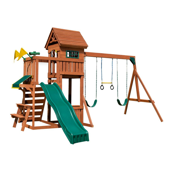
PB 8327
PB 8331
NOTE:
SLIDE NOT INCLUDED
WITH PB 8327
IMPORTANT!!
PLEASE READ BEFORE BEGINNING ASSEMBLY!!
Please make sure all lumber, hardware and accessory parts are accounted for.
If you are missing anything, please DO NOT RETURN to the store where purchased.
Please call our Customer Service Department at the number below.
Visit our web site at: www.swing-n-slide.com or call us at 1-800-888-1232
© Swing-N-Slide Inc.
Printed in USA
LDR 02-28-2018
LA 9152
Advertisement

Related Manuals for Swing-N-Slide PB 8327


Summary of Contents for Swing-N-Slide PB 8327
- Page 1 If you are missing anything, please DO NOT RETURN to the store where purchased. Please call our Customer Service Department at the number below. Visit our web site at: www.swing-n-slide.com or call us at 1-800-888-1232 © Swing-N-Slide Inc. Printed in USA...
- Page 4 6 ft. 6 ft. Denotes Use Zone with Protective Surfacing L+6 ft. 6 ft. Denotes Use Zone with Protective Surfacing 6 ft. 6 ft. 6 ft. Use Zone for Single-Axis Swings Use Zone for Multi-Axis Swings...
- Page 5 DIMENSIONS 6’ -0’’ 14’ -0’’ 14’ -4’’ 6’ -0’’ 28’ -0’’ 11’ -0’’ 6’ -0’’ 14’ -0’’ 6’ -0’’ 26’ -4’’ MINIMUM USE ZONE FOR PLAY EQUIPMENT SHALL EXTEND NO LESS THAN 72” FROM ALL SIDES OF THE PLAY STRUCTURE. SWING USE ZONE EXTENDS NO LESS THAN 168”.
-
Page 6: Tools Required
TOOLS REQUIRED DRILL 1/2” & 7/16’’ SOCKETS & HAMMER ADJUSTABLE TAPE MEASURE WRENCH WRENCH PLIERS SCREWDRIVER PHILLIPS BIT CARPENTER SAFETY GLASSES 1/8” DRILL BIT SQUARE INCLUDED HARDWARE 3” Deck Screw (x9) 2-1/2” Deck Screw (x170) 5/16” Loc Nut (x10) 3/16” Tarp Washer (x6) 5/16”... - Page 7 HARDWARE 1/4 -18 T-Nut (x12) 5/16” x 1-1/2” Lag Screw (x4) Small (x1) Steering Wheel Spacer...
- Page 8 SA6366 BOX 1 of 2 BOARD LIST (2) [PF 6325] 3’’ x 3’’ x 94-1/4’’ (1) [PF 6309] 5/8’’ x 3-3/8’’ x 35’’ (2) [PF 6324] 3’’ x 3’’ x 94-1/4’’ (1) [PF 6331] 5/8’’ x 3-3/8’’ x 31-1/2’’ (1) [PF 6323] 3’’ x 3’’ x 31-1/2’’ TOWER BEAM SUPPORT (1) [PF 6338] 3/4’’...
- Page 9 SA6065 BOX 2 of 2 BOARD LIST (2) [PF 6297] 1-3/8’’ x 3-3/8’’ x 83’’ A-FRAME (20) [PF 6330] 1/2” x 3-5/16” x 36-3/4” SHINGLE (1) [PF 6296] 1-3/8’’ x 3-3/8’’ x 58’’ A-FRAME SUPPORT (2) [PF 6354] 5/8’’ x 3-3/8’’ x 37-3/8’’ (2) [PF 6352] 1-3/8’’...
- Page 10 If you are missing anything, please DO NOT RETURN to the store where purchased. Please call our Customer Service Department at the number below. ASSEMBLY INSTRUCTIONS Visit our website at: www.swing-n-slide.com or call us at 1-800-888-1232 © Swing-N-Slide Printed in USA...
- Page 11 COMPONENTS Beam Clamp Slotted (x6) Telescope (x1) Climbing Rock (x6) Flag Assembly (x2) Trapeze Bar (x1) Iron Man Ring (x2) 33” Dipped Chain (x2) Anchor It Strap (x4) Anchor It (x4)
- Page 12 STEP 1 PANEL A 2-3/8’’ SPACE Flush 8-3/8’’ Check to make sure PF 6354 5/8’’ x 3-3/8’’ x 37-3/8’’ structure is square 18-11/16’’ (4) PF 6309 5/8’’ x 3-3/8’’ x 35’’ 35-5/8’’ 16-5/16’’ 30mm Deck Screws Per Board 5/8’’ 5-3/8’’ PF 6347 5/8’’...
- Page 13 STEP 2 2-3/8’’ PANEL C SPACE Flush Check to make sure PF 6347 5/8’’ x 3-3/8’’ x 31-1/2’’ structure is square (4) PF 6308 5/8’’ x 3-3/8’’ x 35’’ 35-5/8’’ 30mm Deck Screws Per Board PF 6347 5/8’’ x 3-3/8’’ x 31-1/2’’ 5/8’’...
- Page 14 STEP 3 Check to make sure structure is square 2-1/2’’ Deck Screws 18-11/16’’ TO HOLES Flush T-Nut Small 2-1/2’’ Deck Screws Flush 2-1/2’’ Deck Screws Flush PANEL C 2-1/2’’ Deck Screws NOTE: 2-1/2’’ Deck Screws HOLE ORIENTATION T-Nut Small Flush FRAME A Flush 2-1/2’’...
- Page 15 STEP 4 2-1/2’’ Screws 5/16-18 X 4’’ Hex Head Bolt 5/16’’Loc-Washer 5/16’’ Washer PF 6314 1’’ x 3-3/8’’ x 31-1/2’’ FRAME A FLIP FRAME OVER 2-1/2” Deck Screw (x4) 1. Flip frame over and Attach Frame Support Board as shown above.
- Page 16 STEP 5 2-1/2’’ Deck Screws PF 6307 5/8’’ x 3-3/8’’ x 31-1/2’’ (1) PF 6347 5/8’’ x 3-3/8’’ x 31-1/2’’ (2) PF 6310 5/8’’ x 3-3/8’’ x 8-5/16’’ PF 6307 5/8’’ x 3-3/8’’ x 31-1/2’’ T-Nut Small 2-1/2’’ Deck Screws 2-1/2’’...
- Page 17 STEP 6 2-1/2’’ Screws 5/16-18 X 4’’ Hex Head Bolt 5/16’’Loc-Washer 5/16’’ Washer PF 6314 1’’ x 3-3/8’’ x 31-1/2’’ FRAME B FLIP FRAME OVER 2-1/2” Deck Screw (x4) 1. Flip frame over and Attach Frame Support Board as shown above.
- Page 18 STEP 7 Flush 3’’ From Outside 2-1/2’’ Screws of Post Flush PANEL A Check to make sure structure is square 2-1/2’’ Screws 3’’ From 2-1/2’’ Screws outside of post To end of horizontal support. 2-1/2’’ Screws Flush Flush PANEL A Flush to outside edge of 3”x 3”...
- Page 19 STEP 8 Flush 2-1/2’’ Screws Flush 3’’ From Outside of Post 3’’ From Outside of Post to End of Horizontal Support. 2-1/2’’ Screws 2-1/2’’ Screws FRAME A FRAME B Side View of Tower 19-1/2’’ From Outside of Post 2-1/2’’ Screws 2-1/2’’...
- Page 20 STEP 9 2-1/2’’ Screws PF 6346 5/8’’ x 3-3/8’’ x 31-1/2’’ 2-1/2’’ Screws NOTE: HOLE LOCATION 2-1/2” Deck Screw (x4) 1. Attach Tower Support Board as shown.
- Page 21 STEP 10 5/16-18 X 4’’ Hex Head Bolt 5/16’’Loc-Washer 5/16’’ Washer 2-1/2’’ Screws T-Nut Small PF 6352 1-3/8’’ x 3-3/8’’ x 31-1/2’’ 46-5/8’’ 2-1/2” Deck Screw (x4) 1. Attach Frame Support Board as shown.
- Page 22 STEP 11 Flush 2-1/2’’ Screws 2’’ Screw per side (1) PF 6312 (1) PF 6346 5/8’’ x 3-3/8’’ x 31-1/2’’ 1-3/8’’ x 1-3/8’’ x 31-1/2’’ Back of Tower Flush PF 6305 5/8’’ x 3-3/8’’ x 25-3/8’’ NOTE: 2’’ Screw per side PRE-DRILL 55-1/4’’...
- Page 23 STEP 12 (7) PF 6306 5/8’’ x 3-3/8’’ x 31-3/8’’ 1-3/4’’ Screws per board Flush Flush 2-1/2’’ Screws per joint Flush PANEL B 2-1/2” Deck Screw (x8) PANEL B INSTALL 1-3/4” Deck Screw (x42) 1. Install Deck Boards as shown. NOTE: Standard gap between deck boards is 1/8’’.
-
Page 24: Inside View
STEP 13 1-1/4’’ Screws NOTE HOLE LOCATION 2-1/2’’ Screws INSIDE VIEW 77-1/4’’ Flush 2-1/2’’ Screws 26’’ 1-1/4” Deck Screw (x8 ) 2-1/2” Deck Screw (x8) 1. Attach Barrier Support Board and Safety Board as shown. NOTE: Secure Barrier Board from inside barrier as shown. - Page 25 STEP 14 NOTE: MAKE SCREW 1-5/8’’ Screws HEADS FLUSH T-Nut Small 5/16’’Loc-Washer 5/16’’ Washer 5/16-18 X 1-3/4’’ 3’’ Screws Hex Head Bolt PF 6326 1’’ x 3-3/8’’ x 42’’ SUPPORT 3” Deck Screw (x2) 1-5/8” Deck Screw (x2 ) 1. Attach Tower Support Board as shown.
- Page 26 STEP 15 1-3/4’’ Screws Flush PANEL D Flush 1-3/4’’ Screws 1-3/4’’ Screws NOTE: 5/8’’ Offset to Bottom Flush 1-3/4’’ Screws COUNTERBORE 1-3/4’’ Screws Flush Flush FRAME C Flush 1-3/4’’ Screws 2’’ Screws FLIP FRAME OVER T-Nut Small 5/16’’ Washer 5/16-18 X 2-1/2’’ 5/16’’Loc-Washer Hex Head Bolt LIFT FRAME UP...
- Page 27 STEP 16 Check to make sure struc- ture is square 2-1/2’’ Screws 2-1/2’’ Screws FRAME C 2-1/2’’ Screws 2-1/2” Deck Screw (x6) 1. Attach Frame C to Tower as shown.
- Page 28 STEP 17 NOTE: PANEL D NOT SHOWN Flush FOR CLARITY. (2) PF 6349 5/8’’ x 3-3/8’’ x 29-1/2’’ 1-3/4’’ Screws per board 1-3/4’’ Screws per board PF 6312 1-3/8’’ x 1-3/8’’ x 31-1/2’’ Flush NOTE: PRE-DRILL HOLES GOING INTO DECK SUPPORTS 12-3/4’’...
- Page 29 STEP 18 NOTE: PANEL D NOT SHOWN FOR CLARITY. Flush NOTE HOLE LOCATION (7) PF 6348 5/8’’ x 3-3/8’’ x 30-7/8’’ 1-3/4’’ Screws per board 1-3/4” Deck Screw (x42) 1. Install Deck Boards as shown. NOTE: Standard gap between deck boards is 1/8’’.
- Page 30 STEP 19 NOTE: PANEL D 2-1/4’’ PF 6347 5/8’’ x 3-3/8’’ x 31-1/2’’ NOT SHOWN FOR CLARITY. 2-1/2’’ Screws Flush 2-1/2” Deck Screw (x4) 1. Attach Spacer Board as shown.
- Page 31 STEP 20 PF 6323 3’’ x 3’’ x 31-1/2’’ TOWER BEAM SUPPORT 5/16-18 X 6’’ Carriage Bolt Wood Loc-Washer 5/16’’ Washer Loc Nut 1. Attach Tower Beam Support Board as shown.
- Page 32 STEP 21 PF 6299 2 5/8’’x 5-3/8’’x 93’’ Swing Beam 5/16’’ T-Nut 5-1/2’’ Swing Large Hanger Beam Clamp (4) 1-1/4’’ Deck Screws Correct Orientation 1-1/4” Deck Screw (x24) 1. Attach Swing Hanger(s) to swing beam as shown.
- Page 33 STEP 22 PF 6298 2-11/16’’x 3’’x 62’’ A-Frame SB Support 5/16”-18 x 7” Hex Head Bolt 3’’ Screws 3’’ Screws 5/16” Washer 5/16” Washer 5/16” Loc Nut (2) PF 6297 1-3/8’’x 3-3/8’’x 83’’ A-Frame 5/16”-18 x 2-1/2” Hex Head Bolt 5/16”...
- Page 34 STEP 23 (2) Swing Beam Bracket 5/16”-18 x 3-1/2” Hex Head Bolt 5/16” Washer 5/16” Loc Nut 5/16”-18 x 3-1/2” 5/16” Washer Hex Head Bolt 5/16” Washer 5/16” Washer 5/16” Loc Nut 1. Attach Swing Beam Bracket to A-Frame & Swing Beam as shown.
- Page 35 STEP 24 5/16”-18 x 3 1/4” Hex Head Bolt Beam Brace 5/16” Loc Washer 5/16” Washer 5/16-18 T-Nut Small 1. Install Swing Beam Brace as shown.
- Page 36 STEP 25 5/16”-18 x 6” 5/16”-18 x 8-1/2” Carriage Bolt Hex Head Bolt 5/16” Loc Washer 5/16” Wood Loc Washer 5/16” Washer 5/16” Washer 5/16-18 T-Nut Small 5/16” Loc Nut 1. Install Swing Beam as shown.
- Page 37 STEP 26 2-1/2’’ Screws per board NOTE: Window Panel Removed for Clarity. 2-1/2” Deck Screw (x8) 1. Secure Barrier Boards to Swing Beam Support as shown.
- Page 38 STEP 27 PF 6342 5/8’’ x 3-3/8’’ x 7’’ PF 6344 5/8’’ x 3-3/8’’ x 5-3/8’’ 1-3/4’’ Screws Flush 1-3/4’’ Screws 1-3/4” Deck Screw (x4)
- Page 39 STEP 28 Install 30mm Screws With Heads Flushed To Board To Avoid Protrusions. (2) PF 6303 5/8’’ x 3-3/8’’ x 30’’ 30mm Screws per board Flush 1-3/16’’ 30mm Deck Screw (x8) 1. Attach barrier boards as shown.
- Page 40 STEP 29 30mm NOTE: (1) 3’’ Screw Screws LOOK FOR PRE-DRILLED HOLE PF 6321 5/8’’ x 3-3/8’’ x 6-3/4’’ SUN 5/16’’ 5/16’’ CENTERED PF 6319 5/8’’ x 2’’ x 28’’ 6-3/4’’ 6-3/4’’ (2) 1-1/4’’ Deck (2) 1-1/4’’ Deck Screws Screws PF 6351 1’’...
- Page 41 STEP 30 NOTE: SHINGLES OVERHANG RAFTERS 1” NOTE: TURN ROOF ASSEMBLY ON END. CENTER AND CLAMP PF 6355 (4) 1-1/4’’ Deck BEFORE INSTALLING SCREWS. Screws per board (8) PF 6330 1/2’’ x 3-5/16’’ x 36-3/4’’ SHINGLE (2) PF 6355 1-3/8’’ x 1-3/8’’ x 27-3/4’’ (1) 1-1/4’’...
- Page 42 STEP 31 (3) 1-1/4’’ Deck Screws (2) PF 6330 1/2’’ x 3-5/16’’ x 36-3/4’’ SHINGLE (2) 2’’ Deck (5) 1-1/4’’ Deck Screws Screws per board PF 6320 5/8’’ x 3-3/8’’ x 34-3/4’’ PF 6320 5/8’’ x 3-3/8’’ x 34-3/4’’ (4) 2’’ Deck (4) 2’’...
- Page 43 STEP 32 ALIGN SCREWS Flush WITH PRE DRILLS (3) 2-1/2’’ Deck Screws Per side (5) PF 6341 5/8’’ x 5-3/8’’ x 26-7/8’’ Side View Top (4) 2’’ Deck Screws per board Flush (1) PF 6340 5/8’’ x 5-3/8’’ x 26-7/8’’ 2-1/2”...
- Page 44 STEP 33 (1) PF 6341 5/8’’ x 5-3/8’’ x 26-7/8’’ (4) 2’’ Deck Screws Flush (2) 2’’ Deck Screws (2) 2’’ Deck Screws (1) PF 6353 5/8’’ x 3-3/8’’ x 3’’ Side View Bottom 2” Deck Screw (x6) 1. Attach rock wall board and spacer as shown.
- Page 45 STEP 34 (2) Weld Nuts (2) 1-1/4’’ Hex Head Bolts (2) 1/4’’Flat Washer Per Rock (2) 1/4’’ Loc-Washer Per Rock 1. Attach Climbing Rocks as shown.
- Page 46 STEP 35 PF 6303 5/8’’ x 3-3/8’’ x 30’’ Flush 2’’ Screws 23’’ 2-5/8’’ 2-5/8’’ 30mm Screws 1-1/4’’ Screws (6) PF 6327 5/8’’ x 3-3/8’’ x 23’’ Inside View 1-3/16’’ 2” Deck Screw (x4) 30mm Deck Screw (x12) 1-1/4” Deck Screw (x12) 1.
- Page 47 STEP 36 NOTE HOLE PF 6311 3/4’’ x 5-3/8’’ x 21-1/2’’ 1-7/8’’ NOTE HOLES 5’’ 9-5/8’’ (2) PF 6329 1’’ x 3-1/4’’ x 4-5/8’’ TABLE SUPPORT 1-5/8’’ Screws 2’’ 1-3/4’’ Screws 2’’ Top View of Table 1-5/8’’ Screws per board 1-5/8”...
- Page 48 STEP 37 (2) PF 6302 3/4’’ x 3-3/8’’ x 9-3/4’’ TABLE SUPPORT (2) PF 6300 3/4’’ x 3-3/8’’ x 15-3/4’’ BENCH SUPPORT 1-1/4’’ Screws 1-1/4’’ Screws 3’’ 3’’ Flush 2-1/2’’ Screws 11-3/8’’ 13-3/4’’ Flush 6-7/8’’ 6-7/8’’ 25’’ (2) PF 6301 3/4’’ x 3-3/8’’ x 26-7/8’’ PICNIC TABLE LEG Check to make sure structure is square 2’’...
- Page 49 STEP 38 PF 6333 3/4’’ x 3-3/8’’ x 15-1/2’’ PF 6333 3/4’’ x 3-3/8’’ x 15-1/2’’ 2’’ Screws Flush 2’’ Screws Flush Make Certain This Side Has Holes Closest To The Edge. Flush 2’’ Screws per side (2) PF 6332 3/4’’ x 3-3/8’’ x 13’’ ARCH 33-1/2”...
- Page 50 STEP 39 Flush 2’’ Screws per side 3’’ Screw 3’’ Screw 2” Deck Screw (x4) 3” Deck Screw (x2) 1. Attach Tarp Support Frame to tower as shown.
- Page 51 STEP 40 FLAP UP PF 6331 5/8’’ x 3-3/8’’ x 31-1/2’’ 3/4’’ Screws CENTERED 3/16’’ Tarp Washer 2-1/2’’ Screw per joint 1-1/2’’ 3/4’’ Screws 3/16’’ Tarp Washer 3/4’’ Screws 3/16’’ Tarp Washer Tarp Side View 2-1/2” Deck Screw (x4) 3/4” Pan Head Screw (x6) 3/16”...
- Page 52 STEP 41 (2) PF 6334 1-3/8’’ x 3-3/8’’ x 8’’ Flush Flush (8) 1-3/4” Deck Screws Underdeck View (3) 1-3/4” Truss Screws 2” Grade (2) 1-1/4 Deck Screws 1-3/4” Deck Screw (x8) PF 6295 1-3/8’’x3-3/8’’x17-1/4’’ Slide Stake 1-3/4” Truss Screw (x3) 1-1/4”...
- Page 53 STEP 42 (2) 1/4” Washer (2) 1/4’’ x 1-3/4” Pan Screw 11” 1-3/4” Pan Screw (x4) 1. Attach Safety Handles and I.D. Tag as shown.
- Page 54 STEP 43 NOTE: Crimp swing hanger tightly closed Ring-Trap Combo Assembly 1. Attach Quick Link to chain oriented as shown. 2. Attach Quick Link to gym ring as shown. Attach second set of Quick Links (3) links up. Attach Trapeze Bar as shown. 3.
- Page 55 STEP 44 Swing Seat Assembly 1. Take one length of chain and place the outermost link of chain through the Quick Link as shown. 2. Place the Quick Link through the Grommet of the swing seat as shown. 3. Tighten the threaded sleeve of the Quick Link with a suitably sized wrench so that the seat is securely attached and the Quick Link cannot be easily loosened.
- Page 56 STEP 45 Carriage Bolt Spacer Flat Washer Loc Nut Steering Wheel Cap Steering Wheel Assembly 1. Choose a desired location for the Steering Wheel and drill a 5/16” diameter hole through the lumber. NOTE: If lumber is greater than 2” in depth, you will need to counterbore the hole appropriately. 2.
- Page 57 STEP 4600 Telscope Assembly Mounting Screw Mounting Bracket Telescope Assembly 1. Position Mounting Bracket in desired location. 2. Attach Mounting Bracket to the unit using the Mounting Screw provided. 3. Insert the Telescope into the Mounting Bracket as shown. STEP 46 3/4’’...
- Page 58 STEP 47 Fold up 5/16” Washer Anchor-It Strap 1-1/2” Lag Screw Anchor-It 5/16’’ x 1-1/2” Lag Screw (x4) 2. Twist the Anchor-It into the ground until only the loop is exposed. 3. Place Anchor-It Strap thru loop, fold the ends together and attach to the unit as shown. Note: Keep as little play as possible using any of the holes in the strap that work best.
- Page 59 Components, Chains, Hardware and Fasteners – 5 years. These items to be free from defects in workmanship and materials, under normal use Swing-N-Slide® will repair, or at its discretion, replace any part within the stated warranty period which is defective in workmanship or materials.
- Page 60 PRODUCT WARRANTY & REGISTRATION Please register online to properly initiate your product warranty & registration Quick & simple from home or mobile Record your purchase in our system Initiate product warranty Improved customer support Register your product online at www.OnlineWarranty.net...
- Page 61 Call our Customer Support Representatives 1-800-888-1232 Available Monday - Friday, 7am - 5pm (CST) Weekend support available April through July Technical support from experienced customer service representatives who have actually built a swing set themselves. @ Swing-N-Slide Inc. 2016 Printed in USA...
Need help?
Do you have a question about the PB 8327 and is the answer not in the manual?
Questions and answers