Table of Contents
Advertisement
Advertisement
Table of Contents

Related Manuals for Nord Drivesystems NORDAC PRO SK 500P


Summary of Contents for Nord Drivesystems NORDAC PRO SK 500P
- Page 1 BU 0600 – en NORDAC PRO (SK 500P) Manual with installation instructions...
- Page 2 NORDAC PRO (SK 500P) – Manual with installation instructions Circuit diagram Power supply suitable for device (see Alternative example “Digital input power supply via Technical Data) external power source (24 V DC)” Connection message “FI Ready” (default) Alternative example “PTC connected to D15” Electromechanical brake connection (default) Optional braking resistor Top view...
-
Page 3: Table 1: Version List
Any editing or amendment or other utilisation of the document is prohibited. Publisher Getriebebau NORD GmbH & Co. KG Getriebebau-Nord-Straße 1 • 22941 Bargteheide, Germany • http://www.nord.com Fon +49 (0) 45 32 / 289-0 • Fax +49 (0) 45 32 / 289-2253 Member of the NORD DRIVESYSTEMS Group BU 0600 en-3221... - Page 4 NORDAC PRO (SK 500P) – Manual with installation instructions BU 0600 en-3221...
-
Page 5: Table Of Contents
Table of Contents Table of Contents General ................................. 9 Device characteristics ........................10 Delivery ............................13 Scope of delivery ..........................13 Safety, installation and application information ................17 Explanation of markings ........................21 Warning information on the product ....................22 Standards and approvals ......................... - Page 6 NORDAC PRO (SK 500P) – Manual with installation instructions Parameter ..............................76 Parameter overview ......................... 80 5.1.1 Operating display ........................ 83 5.1.2 DS402 parameter ....................... 85 5.1.3 Basic parameter ......................... 98 5.1.4 Motor data / characteristic curve parameters..............106 5.1.5 Control parameters ......................
- Page 7 List of illustrations List of illustrations Figure 1: Installation spacings ..........................27 Figure 2: Frequency inverter with bottom-mounted braking resistor SK BRU5-............ 32 Figure 3: Illustration of a DC-coupling ........................46 Figure 4: Diagram of a DC coupling with an input/feedback unit ................47 Figure 5: ControlBox menu structure ........................
- Page 8 NORDAC PRO (SK 500P) – Manual with installation instructions List of tables Table 1: Version list ..............................3 Table 2: Overview of FI characteristics ........................12 Table 3: Warning symbols on the product ......................22 Table 4: Standards and approvals ......................... 23 Table 5: Technical data bottom mounted braking resistor SK BRU5-...
-
Page 9: General
1 General 1 General The NORDAC PRO (SK 500P - SK 550P) series is based on the tried and tested NORD platform. The frequency inverters are characterised by their compact design and optimum control characteristics, and have uniform parametrisation. The frequency inverters have sensorless current vector control with a wide range of settings. In combination with suitable motor models, which always provide an optimised voltage/frequency ratio, all three-phase asynchronous motors that are suitable for inverter operation and permanently excited synchronous motors can be driven. -
Page 10: Device Characteristics
NORDAC PRO (SK 500P) – Manual with installation instructions 1.1 Device characteristics The NORDAC PRO series is available in various versions. The following gives an overview of the essential characteristics of the particular versions. Characteristic SK … 500P/510P 530P 550P Additional information Operating manual BU 0600... - Page 11 1 General Characteristic SK … 500P/510P 530P 550P Additional information Operating manual BU 0600 Legend Present Not present Optionally available External connection for the control board voltage 24 V DC supply with automatic switch-over between the internal and external 24 V DC –...
-
Page 12: Table 2: Overview Of Fi Characteristics
NORDAC PRO (SK 500P) – Manual with installation instructions Characteristic SK … 500P/510P 530P 550P Additional information Operating manual BU 0600 Legend Present Not present Optionally available Load monitor (Chap. 5.1.7), P525-P529 Lifting gear functionality (Chap. 5.1.3), P107, P114 Process controller / PID controller (Chap. -
Page 13: Delivery
1 General 1.2 Delivery Examine the frequency inverter for transport damage or loose components immediately on delivery / unpacking. In case of damage, contact the carrier immediately and arrange for a careful survey. Important! This also applies if the packaging is undamaged. 1.3 Scope of delivery NOTICE Defect in the device... - Page 14 NORDAC PRO (SK 500P) – Manual with installation instructions Available accessories: Designation Example Description For commissioning, parametrisation and control Technology units for of the inverter, attachment to the inverter SK TU5-CTR (Chap. 3.2) For commissioning, parametrisation and control Technology units for installation of the inverter, in the control cabinet SK CSX-3E...
- Page 15 1 General Designation Example Description Dissipates generated energy from the drive Chassis-mounted braking resistor system by conversion into heat, e.g. during braking Type SK BR2… (Chap. 2.5.3.4) Dissipates generated energy from the drive Bottom-mounted braking resistor system by conversion into heat, e.g. during braking Type SK BRU5…...
- Page 16 NORDAC PRO (SK 500P) – Manual with installation instructions Designation Example Description External IO extension (analog and digital) IO extension SK EBIOE-2 TI 275900210 In preparation Signal converter ± 10 V Signal converter for conversion of the 0 – 10 V Adapter module V/F converter analogue signals from a potentiometer into pulse signals for evaluation at the digital input of the...
-
Page 17: Safety, Installation And Application Information
1 General 1.4 Safety, installation and application information Before working on or with the device, please read the following safety instructions extremely carefully. Please pay attention to all other information from the device manual. Non-compliance can result in serious or fatal injuries and damage to the device or its surroundings. These safety instructions must be kept in a safe place! 1. - Page 18 NORDAC PRO (SK 500P) – Manual with installation instructions After each triggering of a circuit breaker, all live components within this circuit must thus be visually checked for defects and flashover tracks. Also check the connections at the device’s connection terminals.
- Page 19 1 General 4. Phases of life Transport, storage The information in the manual regarding transport, storage and correct handling must be complied with. The permissible mechanical and climatic ambient conditions (see technical data in the manual for the device) must be complied with. If necessary, suitable, adequately dimensioned means of transport (e.g.
- Page 20 NORDAC PRO (SK 500P) – Manual with installation instructions The parametrisation and configuration of the devices must be selected so that no hazards can occur. With certain setting conditions, the device or the motor which is connected to it may start automatically when the mains are switched on.
-
Page 21: Explanation Of Markings
1 General 1.5 Explanation of markings DANGER Indicates an immediate danger, which may result in death or very serious injury if it is not avoided. WARNING Indicates a dangerous situation, which may result in death or serious injury if it is not avoided. CAUTION Indicates a dangerous situation, which may result in minor injuries if it is not avoided. -
Page 22: Warning Information On The Product
NORDAC PRO (SK 500P) – Manual with installation instructions 1.6 Warning information on the product The following warning symbols are used on the product. Supplement to Warning warning Meaning symbol symbol DANGER Electric shock DANGER The device contains powerful capacitors. Because of this, a hazardous voltage may be present for more than 5 minutes after 300 s disconnection from the mains. -
Page 23: Standards And Approvals
1 General 1.7 Standards and approvals All devices across the entire series comply with the standards and directives listed below. Approval Directive Applied standards Certificates Label Low Voltage 2014/35/EU 2014/30/EU EN 61800-5-1 EN 60529 RoHS 2011/65/EU EN 61800-3 (European C310601 Delegated 2015/863 EN 63000... - Page 24 NORDAC PRO (SK 500P) – Manual with installation instructions Frame description Size “Suitable For Use On A Circuit Capable Of Delivering Not More Than 5000 DC Symmetrical Amperes, 410 Volts (-123 Devices) or 715 Volts (-340 Devices) Max., When Protected by R/C Semiconductor fuses, type______, manufactured by _____”, as listed in “Suitable For Use On A Circuit Capable Of Delivering Not More Than ______ rms Symmetrical Amperes, 240 (1- phase) or 480 (3-phase) Volts Max., When Protected by High-Interrupting Capacity, Current Limiting Class...
-
Page 25: Type Code / Nomenclature
1 General 1.8 Type code / nomenclature Unique type codes have been defined for the individual modules and devices. These provide individual details of the device type and its electrical data, protection class, fixing version and special versions. A differentiation is made according to the following groups: Frequency inverters Optional modules 1.8.1... - Page 26 NORDAC PRO (SK 500P) – Manual with installation instructions Frequency inverter type code SK 530P-370-340-A(-xxx) Version variant or special version Radio interference filter: O = without, A = Class A1(C2) Mains voltage: x23 = 230 V, x40 = 400 V Number of mains phases: 1xx = single phase, 3xx = 3-phase Digits before decimal point for power: 0 = 0.xx, 1 = 0x.x0, 2 = 0xx.0 Device rated power: 250 = 0.25 kW, 370 = 0.37 kW, ...
-
Page 27: Assembly And Installation
2 Assembly and installation 2 Assembly and installation The frequency inverters are available in various sizes depending on their output. Attention must be paid to a suitable position when installing. The inverters require sufficient ventilation for protection against overheating .For this the minimum distances from adjacent components above and below the frequency inverter, which could obstruct the air flow apply. -
Page 28: Frequency Inverter Installation
NORDAC PRO (SK 500P) – Manual with installation instructions 2.1 Frequency inverter installation Install the frequency inverter directly on the rear wall of a control cabinet. Sizes 1 and 2 have two mounting holes, size 3 has four mounting holes. Care must be taken that the rear of the cooling element is covered with a flat surface and that the inverter is mounted vertically. -
Page 29: Emc Kit
2 Assembly and installation 2.2 EMC kit Depending on size and configuration level, various EMC kits are optionally available. A shielding plate for the motor connection is supplied as standard for advanced devices (SK 530P and higher). SK 5xxP EMC kit Motor connection Control Signal and encoder... - Page 30 NORDAC PRO (SK 500P) – Manual with installation instructions Installation Sizes 1 and 2 Size 3 EMC Kit SK HE5-EMC-MS-HS12 EMC Kit SK HE5-EMC-MS-HS34 The screw mounting facility for fastening the EMC kit for The EMC kit for the motor connection SK HE5-EMC- the motor connection SK HE5-EMC-MS-HS12 is MS-HS34 is fastened to the underside of the frequency located on the rear side of the frequency inverter.
- Page 31 2 Assembly and installation Installation – Advanced Devices (SK 530P and higher) Sizes 1 and 2 Size 3 The screw mounting facility for fastening the EMC kit is The EMC kit is fastened to the underside of the located on the rear side of the frequency inverter. frequency inverter with three screws.
-
Page 32: Braking Resistor (Br)
NORDAC PRO (SK 500P) – Manual with installation instructions 2.3 Braking resistor (BR) CAUTION Hot surfaces The braking resistor and all other metal components can heat up to temperatures above 70 °C. • Danger of injury due to local burns on contact. •... -
Page 33: Electrical Data For Braking Resistors
2 Assembly and installation 2.3.1 Electrical data for braking resistors Frequency inverter Type Material No. Document 0.25 ... 0.75 kW SK BRU5-1-240-050 275 299 004 TI 275299004 1.1 ... 2.2 kW SK BRU5-2-075-200 275 299 210 TI 275299210 0.25 ... 0.75 kW SK BRU5-1-400-100 275 299 101 TI 275299101... -
Page 34: Monitoring Of The Braking Resistor
NORDAC PRO (SK 500P) – Manual with installation instructions 2.3.2 Monitoring of the braking resistor To prevent overload of the braking resistor, it should be monitored during operation. The most reliable method is thermal monitoring with a temperature switch which is mounted directly on the braking resistor. -
Page 35: Chokes
2 Assembly and installation 2.4 Chokes Frequency inverters cause loads both on the mains side and the motor side (e.g. current harmonics, steep flanks, EMC interference), which may result in malfunctions in system operation and in the frequency inverter. Mains or link circuit chokes are primarily used for protection of the mains, motor chokes primarily reduce influences on the motor side. - Page 36 NORDAC PRO (SK 500P) – Manual with installation instructions Mains choke SK CI5-500/xxx Inverter ID Mains choke SK 5xxP Type Part number Data sheet 0.25 ... 0.75 kW SK CI5-500/004-C 276 993 004 1.1 ... 2.2 kW SK CI5-500/008-C 276 993 008 TI 276993xxx 3.0 ...
-
Page 37: Motor Choke Sk Co5
2 Assembly and installation 2.4.2 Motor choke SK CO5 To reduce interference radiation from the motor cable or to compensate for cable capacitance in long motor cables, an additional output choke (motor choke) can be installed into the inverter output. During installation, care must be taken that the pulse frequency of the frequency inverter is set to 3 …... -
Page 38: Electrical Connection
NORDAC PRO (SK 500P) – Manual with installation instructions 2.5 Electrical Connection WARNING Electric shock Hazardous voltages may be present at the mains input and all power connection terminals (e.g. motor connection terminals, link circuit) even when the device is not in operation. •... -
Page 39: Overview Of Connections
2 Assembly and installation 2.5.1 Overview of connections Depending on the size of the frequency inverter, the connection terminals for the supply cables and the control cables are located in different positions. According to the configuration of the frequency inverter, various terminals are not present. View from top View from below Front view... - Page 40 NORDAC PRO (SK 500P) – Manual with installation instructions Terminal Signal Pin no. Number SK 500P SK 510P SK 530P SK 550P of poles 230 V 400 V 10 V Analog inputs Digital inputs 24 V Digital inputs and outputs –...
-
Page 41: Wiring Guidelines
2 Assembly and installation 2.5.2 Wiring guidelines The devices have been developed for use in an industrial environment. In this environment, electromagnetic interference can affect the device. In general, correct installation ensures safe and problem-free operation. To meet the limiting values of the EMC directives, the following instructions should be complied with. -
Page 42: Electrical Connection Of Power Unit
NORDAC PRO (SK 500P) – Manual with installation instructions 2.5.3 Electrical connection of power unit The following information relates to all power connections to the frequency inverter. This includes: • Mains cable connection X1 (L1, L2/N, L3, PE) • Motor cable connection X2 (U, V, W, PE) •... -
Page 43: Electromechanical Brake
2 Assembly and installation 2.5.3.1 Electromechanical brake NOTICE Power supply for an electromechanical brake Connection of an electromechanical brake to the motor terminals may cause destruction of the brake or the frequency inverter. • Only provide the power supply for an electromechanical brake (or its brake rectifier) via the mains or mains voltage. -
Page 44: Motor Cable
NORDAC PRO (SK 500P) – Manual with installation instructions As delivered, the device is configured for operation in TN or TT networks. For operation in IT networks, simple adaptations must be made. However, these impair the suppression of radio interference. Adaptation is carried out via two screw connections. -
Page 45: Braking Resistor (B+, B-)
2 Assembly and installation 2.5.3.4 Braking resistor (B+, B-) Terminals +B/ B- are intended for the connection of a suitable braking resistor. A short screened connection should be selected. CAUTION Hot surfaces The braking resistor and all other metal components can heat up to temperatures above 70 °C. •... -
Page 46: Figure 3: Illustration Of A Dc-Coupling
NORDAC PRO (SK 500P) – Manual with installation instructions L1 / L L2 / N L3 / - PE L3 L2 L1 PE L3 L2 L1 Ready message from all FIs PE U V W +B -B -DC PE U V W +B -B -DC Coupling if FIs ready Figure 3: Illustration of a DC-coupling... -
Page 47: Figure 4: Diagram Of A Dc Coupling With An Input/Feedback Unit
2 Assembly and installation L1 / L L2 / N L3 / - PE L3 L2 L1 PE L3 L2 L1 PE L3 L2 L1 Input/ feedback unit For information on connection and protection, as well as the necessary accessories, please consult the manufacturer of the input/feedback unit. -
Page 48: Electrical Connection Of The Control Unit
NORDAC PRO (SK 500P) – Manual with installation instructions 2.5.4 Electrical connection of the control unit The control connections differ depending on the version. All control terminals can be simply plugged in and exchanged. To prevent connection errors, the connections are coded and protected against incorrect connection. - Page 49 2 Assembly and installation Information Response time of digital inputs The response time of a digital signal is approx. 4 – 5 ms and consists of the following: Scan time 1 ms Signal stability check 3 ms Internal processing < 1 ms A parallel channel exists for digital inputs DIN2 and DIN3, which relays the signal pulses between 250 Hz and 150 kHz directly to the processor, and therefore makes it possible for an encoder to be evaluated.
- Page 50 NORDAC PRO (SK 500P) – Manual with installation instructions Control voltage External power supply to the device for bus communication or offline connection X6 parameterisation. (SK 530P and higher) 24 V … 30 V, min. 1000 mA, depending on the load on inputs and outputs and use of options Note: Without the mains supply, there is only restricted visibility of the device status, position values and information parameters.
- Page 51 2 Assembly and installation Analogue Actuation of device by external controller, potentiometer or similar. inputs/outputs X10 Analogue input: For control of the output frequency of the FI. Analogue output: For external display or further processing in a following machine. R=10k Switch-over between current and voltage setpoints (or actual values) is performed automatically.
- Page 52 NORDAC PRO (SK 500P) – Manual with installation instructions Digital inputs X11 Actuation of device using an external controller, switch or similar. Each digital input has a response time of ≤ 5ms. Control with internal 24 V: Control with external 7,5 … 30 V: Digital 7.5 ...
- Page 53 2 Assembly and installation Digital inputs and Signalling of operating statuses of the FI outputs X12 24 V DC Maximum load 20 mA With inductive loads: Provide protection (SK 530P or higher) via free-wheeling diode! Digital input 6 P420 [-06] No function Digital output 1 P434 [-03]...
- Page 54 NORDAC PRO (SK 500P) – Manual with installation instructions 2. RJ45 adapter SK TIE5-CAO-2X-RJ45 Part no.: 275292202 Baud rate … 500 kBaud The RJ45 sockets are connected in parallel internally. Termination resistor R = 240 Ω 2 x RJ45: Pin No. 1… 8 CAN_H CAN/CANopen signal CAN_L...
- Page 55 2 Assembly and installation USB Communication Connection of the FI to a PC (alternatively to the RJ12 interface) for communication interface X16 with the NORDCON software (SK 530P or higher) Note: A 24 V supply (X6) is necessary for access to the Ethernet parameters. USB 2.0 Type C (SK 530P or higher) +5 V Supply voltage...
-
Page 56: Incremental Encoder
NORDAC PRO (SK 500P) – Manual with installation instructions Encoder connection The incremental encoder connection is an input for a type with two tracks and TTL-compatible signals for EIA RS 422-compliant drivers. The maximum current consumption of the incremental encoder must not exceed 150 mA. -
Page 57: Table 10: Colour And Contact Assignments For Nord Ttl / Htl Incremental Encoders
2 Assembly and installation Cable colours for Function incremental Signal type TTL Signal type HTL encoders 10-30 V supply Brown / green X13: 43 (24 V) X11: 43 (24 V) 0 V supply White / green X13: 40 X11: 40 Track A Brown X13: 51... -
Page 58: Fans
NORDAC PRO (SK 500P) – Manual with installation instructions 2.7 Fans 2.7.1 Removing the fan Remove the fan by pressing the two fixing points out of the frequency inverter (1). 2.7.2 Installing the fan Fit the fan by pressing the two fixing points into the frequency inverter (1). Take care that the plug connector on the fan matches the socket of the frequency inverter. -
Page 59: Options
3 Options 3 Options 3.1 Overview of option modules The function of the frequency inverter can be extended with a ControlBox SK TU5-CTR, a customer unit SK CU5-… (SK 530P and higher) and other option modules. The options can be plugged in. Either a blank cover or an SK TU5 module can be attached to an SK CU5 module. - Page 60 NORDAC PRO (SK 500P) – Manual with installation instructions Installation Information Modules should not be inserted or removed unless the device is free of voltage. The slots may only be used for the intended modules. Installation of a technology unit separate from the frequency inverter is not possible. It must be connected directly to the frequency inverter.
-
Page 61: Controlbox Sk Tu5-Ctr
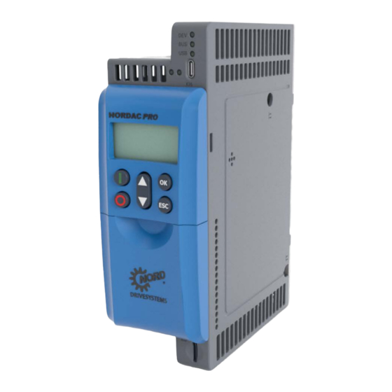
3 Options 3.2 ControlBox SK TU5-CTR The SK TU5-CTR ControlBox is used for commissioning, configuring and controlling the frequency inverter. It is mounted directly on the slot for technology units or on the SK CU5 module. Communication with the inverter and the power supply of the module is provided by a contact rail. -
Page 62: Display
NORDAC PRO (SK 500P) – Manual with installation instructions 3.2.2 Display 3.2.2.1 Displays Inverter load display (with 100% value) Parameter set display Five digit 7-segment display with prefix and 4 x point Three digit 14-segment display for units Enable right and enable left 4 Inverter status displays 3.2.2.2 Operation... -
Page 63: Status Displays
3 Options 3.2.2.3 Status displays Fault present FI is ready to switch-on Warning present Enable (rotates left) present Switch-on inhibit present Enable (rotates right) present 3.2.3 Control The frequency inverter can only be controlled via the control panel, if it has not been previously enabled via the control terminals or via a serial interface (P509 = 0 and P510 = 0). -
Page 64: Parameterisation
NORDAC PRO (SK 500P) – Manual with installation instructions 3.2.4 Parameterisation Switching to parameter mode is performed in different ways depending upon the operating states and the enabling source. 1. If enabling is not present via the control panel, control terminals or a serial interface, switch-over from the operating value display to parameterisation mode can be made directly with ▼... -
Page 65: Figure 5: Controlbox Menu Structure
3 Options Menu structure with the ControlBox Operating value display P7- - (or operational) P6- - _ _ _ _ _ following mains ON P5- - P4- - P0 - - P1- - P3- - P2- - P0 0 1 P40 0 P10 0 P30 0... -
Page 66: Frequency Addition And Subtraction Via Control Boxes
NORDAC PRO (SK 500P) – Manual with installation instructions 3.3 Frequency addition and subtraction via control boxes If the parameter P549 (PotentiometerBox Function) is set to 4 “Frequency addition” or 5 “Frequency ▲ ▼ of the ControlBox or the subtraction”, a value can be added or subtracted using the value keys ParameterBox. -
Page 67: Commissioning
4 Commissioning 4 Commissioning WARNING Unexpected movement Connection of the supply voltage may directly or indirectly set the drive unit into motion. This can cause unexpected movement of the drive and the attached machine, which may result in serious or fatal injuries and/or material damage. -
Page 68: Figure 6: Motor Type Plate
NORDAC PRO (SK 500P) – Manual with installation instructions P200 Motor list: 0 = No change 8 = 0.37kW 400V 1 = No motor 9 = 0.50PS 460V 2 = 0.25kW 230V 10 = 0.55kW 230V 3 = 0.33PS 230V 11 = 0.75PS 230V 4 = 0.25kW 400V 12 = 0.55kW 400V... -
Page 69: Selecting The Operating Mode For Motor Control
4 Commissioning 4.2 Selecting the operating mode for motor control The frequency inverter is able to control motors with all efficiency classes (IE1 to IE4). Motors which we manufacture are produced as asynchronous motors in efficiency classes IE1 to IE3, whereas IE4 motors are produced as synchronous motors. - Page 70 NORDAC PRO (SK 500P) – Manual with installation instructions 3. CFC open-loop –mode (P300, setting "2") CFC mode is also possible with the open-loop method, i.e. in operation without an encoder. Here, the speed and position detection are determined by "observation" of measurements and setting values.
-
Page 71: Overview Of Controller Parameter Settings
4 Commissioning 4.2.2 Overview of controller parameter settings The following illustration provides an overview of all parameters which are important, depending on the selected operating mode. A differentiation is made between “relevant”, and “important”, which provides an indication of the required precision of the relevant parameter setting. However, in principle, the more precise the setting, the more accurate the control and the higher the possible values for the dynamics and precision of drive operation. -
Page 72: Motor Control Commissioning Steps
NORDAC PRO (SK 500P) – Manual with installation instructions 4.2.3 Motor control commissioning steps The main commissioning steps are mentioned below in their ideal order. Correct assignment of the inverter / motor and the mains voltage is assumed. Detailed information, especially for optimisation of the current, speed and position control of asynchronous motors is described in the guide "Control optimisation"... -
Page 73: Minimum Configuration Of Control Connections
4 Commissioning 4.3 Minimum configuration of control connections If the frequency inverter is to be controlled via the digital and analogue inputs, this can be implemented immediately in the condition as delivered. Settings are not necessary for the moment. Minimum circuitry Potentiometer, 10 kOhm (Function P400 [-01] = 1) (min./max. -
Page 74: Temperature Sensors
NORDAC PRO (SK 500P) – Manual with installation instructions 4.4 Temperature sensors The current vector control of the frequency inverter can be further optimised by the use of a temperature sensor. By continuous measurement of the motor temperature, the highest precision of regulation by the frequency inverter and the associated optimum speed precision of the motor is achieved at all times. - Page 75 4 Commissioning Connection examples A temperature sensor can be connected to either of the two analogue inputs of the relevant option. In the following examples, analogue input 2 is used. Parameter settings (Analogue input 2) The following parameters must be set for the function of the temperature sensor. Analogue input 2 function, P400 [-02] = 48 (motor temperature) Analogue input 2 mode, P401 [-02] = 1 (negative temperatures are also measured) (kΩ)
-
Page 76: Parameter
NORDAC PRO (SK 500P) – Manual with installation instructions 5 Parameter WARNING Unexpected movement Connection of the supply voltage may directly or indirectly set the drive unit into motion. This can cause unexpected movement of the drive and the attached machine, which may result in serious or fatal injuries and/or material damage. - Page 77 5 Parameter WARNING Unexpected movement due to overload In case of overload of the drive there is a risk that the motor will "break down" (sudden loss of torque). An overload may be caused e.g. by inadequate dimensioning of the drive unit or by the occurrence of sudden peak loads.
- Page 78 NORDAC PRO (SK 500P) – Manual with installation instructions Menu group Master function Operating displays (P0--) Display of parameters and operational values DS402 parameter (P0--) Parameter for DS402 drive profile Basic parameters (P1--) Basic device settings such as behaviour when switching on/off Motor data (P2--) Electrical settings for the motor (motor current or starting voltage)
-
Page 79: Figure 7: Explanation Of Parameter Description
5 Parameter P000 Operating para. disp. (parameter number) (parameter name) Setting range Display of typical display format (e.g. (bin = binary)) of possible setting range and number of decimal places or display range Arrays [-01] If parameters have a substructure in several arrays, this is shown here. Typical default setting of parameters in the as-delivered condition of the FI, or to which it is set after Factory setting { 0 }... -
Page 80: Parameter Overview
NORDAC PRO (SK 500P) – Manual with installation instructions 5.1 Parameter overview Operating displays P000 Operating para. disp P001 Select of disp.value P002 Display factor P003 Supervisor-Code P004 Password P005 Change password DS402 parameters P020 Target velocity P021 Velocity demand P022 Control effort P023 Velocity amount... - Page 81 5 Parameter Control parameters Control parameters P300 Control method P301 Incremental encoder P310 Speed ctrl P P311 Speed ctrl I P312 Torque curr. ctrl. P P313 Torque curr. ctrl. I P314 Torq curr ctrl limit P315 Field curr. ctrl. P P316 Field curr.
- Page 82 NORDAC PRO (SK 500P) – Manual with installation instructions P558 Flux delay P559 DC Run-on time P560 Mode of param.save P583 Motor phase sequence Information P700 Actual operating status P701 Last fault P702 Freq. last error P703 Current. last error P704 Volt.
-
Page 83: Operating Display
5 Parameter 5.1.1 Operating display P001 Selection of display value Setting range 0 … 65 Factory setting { 0 } Description Selection of the operating display for display via 7-segment display. Display values Value Meaning Actual frequency [Hz] Actually output frequency supplied Speed [rpm] Calculated speed... - Page 84 NORDAC PRO (SK 500P) – Manual with installation instructions P002 Display factor Setting range 0.01 … 9999.99 Factory setting { 1 } The selected operating value in parameter P001 “Select display value” is multiplied by Description the scaling factor in P000 and displayed in the “Operating para. display”. It is therefore possible to display system-specific operating values e.g.
-
Page 85: Ds402 Parameter
5 Parameter 5.1.2 DS402 parameter Information For parameters P046, P047, P048, P056, P057, P062, P063 and P064 the precise designations can be obtained from the arrays. These parameters are indicated with an exclamation mark (!) in the top line. Information If the mains voltage is not connected (X1) the following parameter shows the value 0 and not the actual correct operating value. - Page 86 NORDAC PRO (SK 500P) – Manual with installation instructions P024 6048 Velocity accele Setting range [-01] = 1... 2400000 rpm [-02] = 0... 32767 sec Arrays [-01] = Delta-N acceleration [-02] = Delta-T acceleration Factory setting [-01] = { 1500 } [-02] = { 2 } PDO mapping...
- Page 87 5 Parameter Information If the mains voltage is not connected (X1) the following parameter shows the value 0 and not the actual correct operating value. P029 6041 Status word Display range -32768 … 32767 Factory setting { 0 } PDO mapping TxPDO Data type UNSIGNED 16 Bit...
- Page 88 NORDAC PRO (SK 500P) – Manual with installation instructions Information If the mains voltage is not connected (X1) the following parameter shows the value 0 and not the actual correct operating value. P032 6061 Act. operating mode Display range -1 … 6 Factory setting { 3 } PDO mapping...
- Page 89 5 Parameter Information If the mains voltage is not connected (X1) the following parameter shows the value 0 and not the actual correct operating value. P034 60FD Actual dig. in. Display range -2147483648 … 2147483647 Factory setting { 0 } PDO mapping TxPDO Data type...
- Page 90 NORDAC PRO (SK 500P) – Manual with installation instructions Setting values Value Function Description Bit: 0 Set brake Brake control Bit: 1 … 15 reserved Bit: 16 Multi-function relay 1 (K1) Bit: 17 Multi-function relay 2 (K2) Bit: 18 Digital output 1 (DO1) Bit: 19 Digital output 2 (DO2) Bit: 20...
- Page 91 5 Parameter P047 6065& 6066 Follow error Arrays [-01] = 6065 Follow error wind [-02] = 6066 Follow error time Setting range [-01] = 0 … 2147483,647 rev [-02] = 0... 32767 ms Factory setting [-01] = { 0 } [-02] = { 200 } PDO mapping...
- Page 92 NORDAC PRO (SK 500P) – Manual with installation instructions P052 6081 Profile speed. Setting range 0... 24.000 rev Factory setting { 1500 } PDO mapping RxPDO Data type UNSIGNED 32 Bit Description DS402 object 6081h: Speed setpoint in “Profile Position” and “Profile Velocity” modes. P053 6086 Position type Setting range...
- Page 93 5 Parameter P055 608A Pos. unit Setting range 0 … 1 Factory setting { 0 } PDO mapping Data type UNSIGNED 8 Bit Description DS402 object 608Ah: Setting of the unit. Setting values Value Function Description rev [rotations] m [Metre P056 6091 Speed ratio/ negative speed ratio Arrays...
- Page 94 NORDAC PRO (SK 500P) – Manual with installation instructions P058 6098 Ref. pt.f.Mode Setting range 0 … 35 Factory setting { 0 } PDO mapping Data type INTEGER 8 Bit Description DS402 object 6098h: Setting of the required reference run method. Setting values Value Function...
- Page 95 5 Parameter P059 6099 Ref. Pt. for speed Arrays [-01] = 6099 Ref. Pt. for speed [1] [-02] = 6099 Ref. Pt. for speed [2] Setting range [-01] = 0 … 24000 rpm [-02] = 0 … 24000 rpm PDO mapping [-01] = [-02] = Data type...
- Page 96 NORDAC PRO (SK 500P) – Manual with installation instructions P063 606D & 606E Velocity window Setting range [-01] = 0 … 24000 rpm [-02] = 0 … 32767 ms Arrays [-01] = 606D Velocity window [-02] = 606E Velocity window time Factory setting [-01] = { 100 }...
- Page 97 5 Parameter P072 60FF Speed profile Setting range -24000... 24000 rpm Factory setting { 0 } PDO mapping RxPDO Data type INTEGER 32 Bit Description DS402 object 60FFh: Target speed in “Profile Velocity” operating mode. P073 6077 Act. torque Display range -400...
-
Page 98: Basic Parameter
NORDAC PRO (SK 500P) – Manual with installation instructions 5.1.3 Basic parameter P100 Parameter set Setting range 0 … 3 Factory setting { 0 } Description Selection of the parameters sets to be parameterised. Four parameter sets are available. The parameters to which different values can also be assigned in the four parameter sets are known as “parameter set-dependent”... - Page 99 5 Parameter P103 Deceleration time Setting range 0.00 … 320.00 s Factory setting { 2.00 } Description The deceleration time is the time corresponding to the linear frequency reduction from the set maximum frequency P105 to 0 Hz. If an actual setpoint <100 % is being used, the deceleration time reduces accordingly.
- Page 100 NORDAC PRO (SK 500P) – Manual with installation instructions P106 Ramp smoothing Setting range 0 … 100 % Factory setting { 0 } Description This parameter enables smoothing of the acceleration and deceleration ramps. This is necessary for applications where gentle, but dynamic speed change is important. Ramp smoothing is carried out for every setpoint change.
- Page 101 5 Parameter P107 Brake reaction time Setting range 0 … 2.50 s Factory setting { 0.00 } Description Electromagnetic brakes have a physically-dependent delayed Brake reaction time when actuated. This can result in the dropping of the load in lifting equipment applications.
- Page 102 NORDAC PRO (SK 500P) – Manual with installation instructions P108 Switch-off mode Setting range 0 ... 13 Factory setting { 1 } Description This parameter determines the way in which the output frequency is reduced after "Blocking" (controller enable Low). Setting values Value Meaning...
- Page 103 5 Parameter P109 DC brake current Setting range 0 … 250 % Factory setting { 100 } Description Current setting for the functions of DC current braking (P108 = 3) and combined braking (P108 = 5). The correct setting value depends on the mechanical load and the required deceleration time.
- Page 104 NORDAC PRO (SK 500P) – Manual with installation instructions P111 P - torque limit factor Setting range 25 … 400 % Factory setting { 100 } "P torque limit factor". Directly affects the behaviour of the drive at the torque limit. Description The basic setting of 100 % is sufficient for most drive tasks.
- Page 105 5 Parameter P114 Brake delay off Setting range 0.00 … 2.50 s Factory setting { 0.00 } Description Electromagnetic brakes have a delayed reaction time for their release, which depends on physical factors. This can lead to the motor running while the brake is still applied, which will cause the inverter to switch off with an overcurrent message.
-
Page 106: Motor Data / Characteristic Curve Parameters
NORDAC PRO (SK 500P) – Manual with installation instructions 5.1.4 Motor data / characteristic curve parameters P200 Motor list Setting range 0 … 148 Factory setting { 0 } Description The factory settings for the motor data can be edited with this parameter. The factory setting in parameters P201 ... - Page 107 5 Parameter 0.12kW 115V 1.10 kW 230 V 90T1/4 2.20 kW 400 V 90T1/4 0.18kW 115V 1.10 kW 230 V 80T1/4 3.00 kW 230 V 100T5/4 0.25kW 115V 1.10 kW 400 V 80T1/4 3.00 kW 230 V 100T2/4 0.37kW 115V 1.50 kW 230 V 90T3/4 3.00 kW 400 V 100T2/4 0.55kW 115V...
- Page 108 NORDAC PRO (SK 500P) – Manual with installation instructions P205 Nominal power Setting range 0.00 … 250.00 kW Factory setting The default setting depends on the nominal power of the FI. Description Displays the nominal motor power P206 Cos phi Setting range 0.50 …...
- Page 109 5 Parameter P209 No-load current Setting range 0.0 … 1000.0 A Factory setting The default setting depends on the nominal power of the FI. Description This value is always calculated automatically from the motor data if there is a change in the parameter P206 "Cos ϕ"...
- Page 110 NORDAC PRO (SK 500P) – Manual with installation instructions P212 Slip compensation Setting range 0 ... 150 % Factory setting { 100 } Description Slip compensation increases the output frequency depending on the load, in order to keep the three-phase asynchronous motor speed approximately constant. The factory setting of 100% is optimal for three-phase asynchronous motors if the correct motor data has been set.
- Page 111 5 Parameter P216 Boost precontrol. Setting range 0.0 ... 10.0 s Factory setting { 0.0 } Description This parameter is used for 3 functionalities: 1. Time limit for the boost precontrol: Application time for the increased starting current. Only with linear characteristic curve (P211 = 0 % and P212 = 0 %). 2.
- Page 112 NORDAC PRO (SK 500P) – Manual with installation instructions P219 Auto. flux adjustment Setting range 25 ... 100 % / 101 Factory setting { 100 } "Automatic magn. adjustment". With this parameter, the magnetic flux of the motor Description can be automatically matched to the motor load, so that the energy consumption is reduced to the amount which is actually required.
- Page 113 5 Parameter P2xx Control/characteristic curve parameters Output voltage P204 P211 P215 P210 Output frequency P201 NOTE: P216 Time "typical" Settings for the... Current vector control (factory setting) Linear V/f characteristic curve P201 to P209 = Motor data P201 to P209 = Motor data P210 = 100% P210 = 100% (static boost) P211 = 100%...
- Page 114 NORDAC PRO (SK 500P) – Manual with installation instructions Information If the mains voltage is not connected (X1) the following parameter shows the value 0 and not the actual correct operating value. P220 Par.-identification Setting range 0 ... 2 Factory setting { 0 } “Parameter identification”.
- Page 115 5 Parameter P240 EMF voltage PMSM Setting range 0 … 800 V Factory setting { 0 } Description The EMF voltage PMSM describes the self induction voltage of the motor. The value to be set can be found on the data sheet for the motor or on the type plate and is scaled to 1000 rpm.
- Page 116 NORDAC PRO (SK 500P) – Manual with installation instructions P244 Peak current PMSM Setting range 0.1 … 1000.0 A Arrays [-01] = Peak current PMSM [-02] = Imax unsaturated Ld [-03] = Imax unsaturated Lq [-04] = Imin saturated Ld [-05] = Imin saturated Lq Factory setting...
-
Page 117: Control Parameters
5 Parameter 5.1.5 Control parameters P300 Control method Setting range 0 … 2 Factory setting { 0 } Description The control method for the motor is defined with this parameter. The following constraints must be observed: In comparison with setting {0}, setting {2} enables higher dynamics and control precision, however it requires greater effort for parameterisation. - Page 118 NORDAC PRO (SK 500P) – Manual with installation instructions P310 Speed controller P Setting range 0 … 3200 % Factory setting { 100 } Description P-component of the encoder (proportional amplification). Amplification factor, by which the speed difference between the setpoint and actual frequency is multiplied.
- Page 119 5 Parameter P315 Field curr. ctrl. P Setting range 0 … 1000 % Factory setting { 400 } Description Current controller for the field current. The higher the current controller parameters are set, the more precisely the current setpoint is maintained. At low frequencies, excessively high values of P315 generally result in high frequency oscillations.
- Page 120 NORDAC PRO (SK 500P) – Manual with installation instructions P320 Weak border Setting range 0 … 110 % Factory setting { 100 } Description The field weakening limit determines the speed /current at which the controller begins to weaken the field. At a set value of 100 % the controller begins to weaken the field at approximately the synchronous speed.
- Page 121 5 Parameter P326 Ratio encoder Setting range 0.01 … 100.00 Arrays [-01] = [-02] = [-03] = Sin/Cos Factory setting { 1.00 } "Ratio encoder". If the incremental encoder is not mounted directly onto the motor Description shaft, then the respectively correct ratio of motor speed to encoder speed must be set. Motor speed P326 = Encoder speed...
- Page 122 NORDAC PRO (SK 500P) – Manual with installation instructions P330 Ident startrotor pos Setting range 0 … 7 { 1 } Factory setting { 1 } "Ident startrotor pos". Selection of the method for determination of the starting position Description of the rotor (initial value of the rotor position) of a PMSM (Permanent Magnet Synchronous Motor).
- Page 123 5 Parameter P331 Switch over freq. Setting range 5.0 ... 100.0 % Factory setting { 15.0 } "Switch over freq.“. Definition of the frequency above which, in operation without Description encoder, the control method is activated according to P300 . In this case, 100 % corresponds to the nominal motor frequency from P201.
- Page 124 NORDAC PRO (SK 500P) – Manual with installation instructions P336 Mode rotorpos ident Setting range 0 … 3 Factory setting { 0 } "Mode rotorpos ident" The precise position of the rotor must be known in order to Description operate a PMSM. This can be determined by various methods. Note Use of the parameter is only advisable if the test signal method is set (P330).
- Page 125 5 Parameter P351 PLC set val. select. Setting range 0 … 3 Factory setting { 0 } Description Selection of the source for the control word (CTW) and the main setpoint (MSW) with active PLC functionality P350 = {1}). With the settings P351 ={0} and {1} the main setpoints are defined via P553, but the definition of the auxiliary setpoints remains unchanged via P546.
- Page 126 NORDAC PRO (SK 500P) – Manual with installation instructions Information If the mains voltage is not connected (X1) the following parameter shows the value 0 and not the actual correct operating value. P360 PLC display value Display range - 2 147 483.648 … 2 147 483.647 Arrays [-01] …...
-
Page 127: Control Terminals
5 Parameter 5.1.6 Control terminals Information The input functions {48} and {58} do not function with the following parameter P400 without connection of a mains voltage (X1). P400 Analog input func. Setting range 0 … 58 Arrays [-01] = Analog input 1 Analogue input 1 (AI1) integrated into the FI [-02] = Analog input 2... - Page 128 NORDAC PRO (SK 500P) – Manual with installation instructions Current limit Based on the set current limit P536, this can be changed via the analogue input. Maximum frequency The maximum frequency of the FI is varied. 100 % corresponds to the setting in parameter P411.
- Page 129 5 Parameter P401 Analog input mode Setting range 0 … 5 Arrays [-01] = Analog input 1 Analogue input 1 (AI1) integrated into the FI [-02] = Analog input 2 Analogue input 2 (AI2) integrated into the FI "External analog input 1". Analogue input 1 of the [-03] = Ext.
- Page 130 NORDAC PRO (SK 500P) – Manual with installation instructions 0 – 10V monitored: If the minimum adjusted setpoint P402 is undershot by 10 % of the difference value from P403 and P402, the FI output switches off. Once the setpoint is greater than P402 - (10 % * (P403 … P402)), it will deliver an output signal.
- Page 131 5 Parameter P402 Analog input matching 0% Setting range -500.0 ... 500.0 % Arrays [-01] = Analog input 1 Analogue input 1 (AI1) integrated into the FI [-02] = Analog input 2 Analogue input 2 (AI2) integrated into the FI "External analog input 1".
- Page 132 NORDAC PRO (SK 500P) – Manual with installation instructions P403 Analog input adjustment 100% Setting range -500.0 ... 500.0 % Arrays [-01] = Analog input 1 Analog input 1 (AI1) integrated into the FI [-02] = Analog input 2 Analog input 2 (AI2) integrated into the FI "External analog input 1".
- Page 133 5 Parameter P404 Analog input filter Setting range 1 ... 400 ms Arrays [-01] = Analog input 1 Analogue input 1 (AI1) integrated into the FI [-02] = Analog input 2 Analogue input 2 (AI2) integrated into the FI [-03] = Reserve [-04] = Reserve...
- Page 134 NORDAC PRO (SK 500P) – Manual with installation instructions P411 Max. freq. aux. setpoint Setting range -400.0 ... 400.0 Hz Factory setting { 50.0 } "Maximum frequency auxiliary setpoints". The maximum frequency that can act on the Description setpoint via the auxiliary setpoints. Auxiliary setpoints are all frequencies that are additionally delivered for further functions in the FI: •...
- Page 135 5 Parameter P415 PID control D comp. Setting range 0 ... 400.0 % / ms Factory setting { 1.0 } This parameter is only effective if the function „”PID actual frequency” is selected. Description The D-component of the PID controller determines the frequency change depending on time. If a function of the analogue inputs is set to the function “Actual value process controller”, this parameter determines the controller limitation (%) after the PI controller.
- Page 136 NORDAC PRO (SK 500P) – Manual with installation instructions Information If the following parameter P418 is to be used in the function of an analogue output, all functions are inactive or the value 0 V is output unless the mains voltage (X1) is applied. However, if P418 is to be used as a digital output, function {61} must be selected.
- Page 137 5 Parameter Torque [%] The actual torque calculated by the FI. Field [%] The actual field in the motor calculated by the FI. Actual frequency ± The analogue voltage is proportional to the output frequency of the FI, whereby the zero point is shifted to 5 V. For CW direction of rotation, values from 5V to 10 V are output and for CCW rotation values from 5 V to 0 V.
- Page 138 NORDAC PRO (SK 500P) – Manual with installation instructions P419 Analog output scaling Setting range -500 ... 500 % Arrays [-01] = Analog output 1 Analogue output (AO) integrated into the FI [-02] = Reserve "External analog output of first IOE“. Analogue [-03] = First IOE output of the first IO extension...
- Page 139 5 Parameter Information With the following parameter P420, except for fault acknowledgement via function {1}, “Enable right”, {2} and {3} “Fault acknowledgement“, none of the input functions operate unless a mains voltage (X1) is connected. P420 Digital inputs Setting range 0 …...
- Page 140 NORDAC PRO (SK 500P) – Manual with installation instructions Fixed frequency 1 The frequency from P429 is added to the actual setpoint. High Fixed frequency 2 The frequency from P430 is added to the actual setpoint. High Fixed frequency 3 The frequency from P431 is added to the actual setpoint.
- Page 141 5 Parameter 3-W-Ctrl.Start-Right "3-Wire-Control". This control function provides an alternative to 01 (closing switch for enable R/L{01, 02}, for which permanently applied levels are Flank enable right) required. Here, only a control pulse is required to trigger the function. 3-W-Ctrl.Start-Left 01 Control of the FI can therefore be performed entirely with keys.
- Page 142 NORDAC PRO (SK 500P) – Manual with installation instructions P425 Function PTC input Setting range 0 … 1 Factory setting { 1 } Scope of application SK 530P, SK 550P Description A connected thermistor is evaluated by the device. This function must be disabled if no thermistor is connected.
- Page 143 5 Parameter P428 Automatic starting Setting range 0 … 1 Factory setting { 0 } Description WARNING! Danger of injury due to unexpected movements of the drive chain. Switch-on after an earth fault/short-circuit. Do NOT parameterise this parameter to “On” (P428 = 1), if “Automatic acknowled.” (P506 = 6 “Always”) has been parameterised! Secure drive chain against movements.
- Page 144 NORDAC PRO (SK 500P) – Manual with installation instructions P430 Fixed frequency 2 Setting range -400.0 … 400.0 Hz Factory setting { 0.0 } Description For a description of the function of the parameter, see P429 “Fixed frequency 1”. P431 Fixed frequency 3 Setting range -400.0 …...
- Page 145 5 Parameter Information For the following parameter P434 all functions are disabled or 0V is output unless the mains voltage (X1) is applied. This does not include the following functions: {7}, {8}, {12}, {30} – {37}, {38} and {50} – {59}.
- Page 146 NORDAC PRO (SK 500P) – Manual with installation instructions Torque current limit Based on motor data settings in P203 and P206. Signals High a corresponding torque load on the motor. This value can be adjusted with scaling P435. Frequency limit Based on the motor frequency setting in P201.
- Page 147 5 Parameter Value Bus setpoint Value from Bus setpoint (P546 …) High STO inactive The relay / bit deactivates if STO or Safe Stop are active. High Output via PLC The output is set by the integrated PLC High Comparison value AI1, Comparison of AIN1 with the value which can be set in the adjustment value P435.
- Page 148 NORDAC PRO (SK 500P) – Manual with installation instructions P436 Dig. out. hysteresis Setting range 1 … 100 % Arrays [-01] = Binary output.1 / MFR1 Multi-function relay 1 (K1) integrated into the FI [-02] = Binary output.2 / MFR2 Multi-function relay 2 (K2) integrated into the FI [-03] = Digital output 1 Digital output 1 (DO1) integrated into the FI...
- Page 149 5 Parameter P464 Fixed frequency mode Setting range 0 … 1 Factory setting { 0 } Description This parameter determines the form in which fixed frequencies are to be processed. Note The highest active fixed frequency is added to the setpoint value of the motor potentiometer if functions 71 or 72 are selected for two digital inputs.
- Page 150 NORDAC PRO (SK 500P) – Manual with installation instructions P475 Delay on/off switch Setting range -30,000 ... 30,000 s Arrays [-01] = Digital input 1 Digital input 1 (DI1) integrated into the FI [-02] = Digital input 2 Digital input 2 (DI2) integrated into the FI [-03] = Digital input 3 Digital input 3 (DI3) integrated into the FI...
- Page 151 5 Parameter Information With the following parameter P480 the Bus IO bits are regarded as digital inputs by P420. Therefore, the input functions {8}, {13}, {17}, {18}, {61} and {80} – {82} do not operate without the application of a mains voltage (X1).
- Page 152 NORDAC PRO (SK 500P) – Manual with installation instructions Information With the following parameter P481 the Bus IO bits are regarded as digital inputs by P434. Therefore, none of the functions operate without the application of a mains voltage. An exception to this is if one of the following functions has been selected: {7}, {8}, {12}, {30} –...
- Page 153 5 Parameter P480 … P481 Use of Flags With the aid of the two flags it is possible to define simple logical sequences of functions. For this, in parameter P481 the “trigger” of a function is defined in the arrays [-09] “Flag 1” and [- 10] “Flag 2”...
- Page 154 NORDAC PRO (SK 500P) – Manual with installation instructions P482 Norm. BusIO Out Bits Setting range -400 … 400 % Arrays [-01] = Bus / Dig Out 1 [-02] = Bus / Dig Out 2 Out Bit 0 … 3 via Bus [-03] = Bus / Dig Out 3 [-04] =...
- Page 155 5 Parameter P483 Hyst. BusIO Out Bits Setting range 1 … 100 % Arrays [-01] = Bus / Dig Out 1 [-02] = Bus / Dig Out 2 Out Bit 0 … 3 via Bus [-03] = Bus / Dig Out 3 [-04] = Bus / Dig Out 4 [-05] =...
-
Page 156: Additional Parameters
NORDAC PRO (SK 500P) – Manual with installation instructions 5.1.7 Additional parameters P501 Inverter name Setting range A … Z (char) Arrays [-01] … [-20] Factory setting { 0 } Description Free input of a designation (name) for the device (max. 20 characters). With this, the frequency inverter can be uniquely identified for setting with NORDCON software or within a network. - Page 157 5 Parameter P503 Leading func. output Setting range 0 … 5 Factory setting { 0 } Description For master-slave applications this parameter specifies on which bus system the master transmits the control word and the master values P502 for the slave. On the slave, parameters P509, P510, P546 define the source from which the slave obtains the control word and the master values from the master and how these are to be processed by the slave.
- Page 158 NORDAC PRO (SK 500P) – Manual with installation instructions P504 Pulse frequency Setting range 4.0 ... 16.4 kHz Factory setting { 6.0 } Description The internal pulse frequency for controlling the power unit can be changed with this parameter. A higher setting value reduces motor noise, but leads to increased EMC emissions and reduction of the possible motor torque.
- Page 159 5 Parameter P505 Absolute mini. freq. Setting range 0.0 … 10.0 Hz Factory setting { 2 } “Absolute minimum frequency”. Specifies the frequency value that cannot be Description undershot by the FI. If the setpoint becomes smaller than the absolute minimum frequency, the FI switches off or changes to 0.0 Hz.
- Page 160 NORDAC PRO (SK 500P) – Manual with installation instructions P509 Control word source Setting range 0 ... 10 Factory setting { 0 } Description Selection of the interface via which the frequency inverter receives its control word (for enabling, direction of rotation, etc.). Note Note P510! For parameterisation via the bus: Set P509 and if necessary P899 to the relevant bus...
- Page 161 5 Parameter P510 Source Setpoints Setting range 0 … 10 Arrays Selection of setpoint source. [-01] = Main set value [-02] = Auxiliary set value Factory setting All { 0 } Description Selection of the interface from which the frequency inverter receives its setpoints. Setting values Value Meaning...
- Page 162 NORDAC PRO (SK 500P) – Manual with installation instructions P513 Telegram time-out Setting range -0.1 ... 100.0 sec Arrays [-01] = USS / Modbus [-02] = [-03] = CANopen / CAN [-04] = Ethernet Scope of application [-01] SK 500P and higher [-02] SK 530P and higher [-03]...
- Page 163 5 Parameter P514 CAN baud rate Setting range 0 … 7 Factory setting { 5 } Description Used to set the transfer rate (transfer speed) via the CAN bus interface. All bus participants must be set to the same baud rate. Setting values Value Meaning...
- Page 164 NORDAC PRO (SK 500P) – Manual with installation instructions P517 Skip freq. area 1 Setting range 0.0 … 50.0 Hz Factory setting { 2.0 } Description Skip range for "Skip freq. area 1" P516. This frequency value is added and subtracted from the skip frequency.
- Page 165 5 Parameter P520 Flying start Setting range 0 … 4 Factory setting { 0 } Description This function is required to connect the FI to motors which are already rotating, e.g. for fan drives. Note For physical reasons, flying start only operates above 1/10 of the nominal motor frequency P201, however not below 10 Hz.
- Page 166 NORDAC PRO (SK 500P) – Manual with installation instructions P522 Flying start offset Setting range -10.0 … 10.0 Hz Factory setting { 0.0 } "Flying start offset“. A frequency value that can be added to the frequency value Description found, e.g. to remain in the motor range and so avoid the generator range and therefore the chopper range.
- Page 167 5 Parameter P525 … P529 Load monitoring With load monitoring, a range can be specified within which the load torque may change depending on the output frequency. There are three auxiliary values for the maximum permissible torque and three auxiliary values for the minimum permissible torque. A frequency is assigned to each of these auxiliary values.
- Page 168 NORDAC PRO (SK 500P) – Manual with installation instructions P526 Load monitoring min. Setting range 0 / 1 ... 400 % Arrays Selection of up to 3 auxiliary values: [-01] = Auxiliary value 1 [-02] = Auxiliary value 2 [-03] = Auxiliary value 3 Factory setting All { 0 }...
- Page 169 5 Parameter P529 Mode load control Setting range 0 … 3 Factory setting { 0 } Description Specifies the response on infringement of the monitoring range (P525 … P527). Setting values Value Meaning Fault and warning Infringement of the monitoring range produces a warning "E12.5" after the elapse of the time defined in parameter P528.
- Page 170 NORDAC PRO (SK 500P) – Manual with installation instructions P535 t Motor Setting range 0 … 24 Factory setting { 0 } Description The motor temperature is calculated depending on the output current, the time and the output frequency (cooling). If the temperature limit value is reached then switch off occurs with error message E2.1.
- Page 171 5 Parameter P537 Pulse Disconnection Setting range 10 ... 200 % / 201 Factory setting { 150 } Description This function prevents rapid shutdown of the FI according to the load. With the pulse switch-off enabled, the output current is limited to the set value. This limitation is implemented by brief switching off of individual output stage transistors;...
- Page 172 NORDAC PRO (SK 500P) – Manual with installation instructions P539 Check output voltage Setting range 0 ... 3 Factory setting { 0 } Description The output current at the U-V-W terminals is monitored and checked for plausibility. In case of error, the error message E016 is output. Note This function can be used as an additional protective function for lifting applications, but is not permissible on its own as protection for persons.
- Page 173 5 Parameter P541 Set digital out Setting range 0000 … 3FFF (hex) Arrays [-01] = Internal (Set relays) [-02] = Set Bus / IOE Out Factory setting { 0000 } "Set relays and digital outputs". This function provides the option of controlling the Description relay and the digital outputs independently of the frequency inverter status.
- Page 174 NORDAC PRO (SK 500P) – Manual with installation instructions Information The input functions {10}, {11}, {13} to {16}, {53} to {57} and {58} do not function with the following parameter P543 without connection of a mains voltage (X1). P543 Bus actual value Setting range 0 …...
- Page 175 5 Parameter Information The input functions {21} to {46}, {48} and {58} do not function with the following parameter P546 without connection of a mains voltage (X1). P546 Funct. Bus set point Setting range 0 … 57 Arrays [-01] = Bus set point 1 [-02] = Bus set point 2...
- Page 176 NORDAC PRO (SK 500P) – Manual with installation instructions P549 Pot Box function Setting range 0 … 16 Factory setting { 0 } Description This parameter provides the option of adding a correction value (fixed frequency, analogue value, bus) to the actual setpoint value by means of the ControlBox keyboard.
- Page 177 5 Parameter P551 Drive profile Setting range 0 … 3 Factory setting { 0 } Description Activation of a process data profile. Setting values Value Meaning No specific drive profile. CANopen DS402 CANopen drive profile according to DS402. Reserve Nord-Custom Drive profile with freely assignable bits.
- Page 178 NORDAC PRO (SK 500P) – Manual with installation instructions P552 CAN master cycle Setting range 0 … 100 ms Arrays [-01] = CAN master function, CAN master cycle 1 [-02] = CANopen absolute encoder, CANopen absolute encoder, CAN master cycle 2 Factory setting All { 0 } Description...
- Page 179 5 Parameter P553 PLC set values Setting range 0 … 57 Arrays [-01] = PLC setpoint 1 [-02] = PLC setpoint 2 [-03] = PLC setpoint 3 [-04] = PLC setpoint 4 [-05] = PLC setpoint 5 Factory setting All { 0 } Description Assignment of functions for the various PLC control bits.
- Page 180 NORDAC PRO (SK 500P) – Manual with installation instructions P555 P chopper limit Setting range 5 … 100 % Factory setting { 100 } "Chopper power limit“. With this parameter it is possible to program a manual (peak) Description power limit for the braking resistor. The switch-on delay (modulation level) for the chopper can only rise to a certain maximum specified limit.
- Page 181 5 Parameter P558 Flux delay Setting range 0, 1, 2... 5000 ms Factory setting { 1 } Description The ISD control can only function correctly if there is a magnetic field in the motor. For this reason, a DC current is applied before starting the motor to provide excitation of the stator winding.
- Page 182 NORDAC PRO (SK 500P) – Manual with installation instructions P583 Motor phase sequence Setting range 0 ... 2 Factory setting { 0 } Description The motor phase control sequence (U – V – W) can be changed with this parameter. This enables the direction of rotation of the motor to be changed without changing the motor connections.
-
Page 183: Positioning
5 Parameter 5.1.8 Positioning Parameter group P6xx is used to adjust the POSICON positioning control. A detailed description of these parameters can be found in manual 0610. BU 0600 en-3221... -
Page 184: Information
NORDAC PRO (SK 500P) – Manual with installation instructions 5.1.9 Information P700 Actual operating status Display range 0.0 … 99.9 Arrays [-01] = Actual error Indicates the presently active (unacknowledged) fault. [-02] = Actual warning Indicates a present warning message. [-03] = Reason for switch-on Indicates the reason for active switch-on inhibit. - Page 185 5 Parameter P704 Volt. last error Display range 0... 500 V AC Arrays [-01] … [-10] “Last voltage error 1 … 10”. This parameter stores the output voltage that was being Description delivered at the time the fault occurred. The values of the last 10 errors are stored. P705 Dc.lnk volt.
- Page 186 NORDAC PRO (SK 500P) – Manual with installation instructions P708 Digital input status Display range 0000 ... 1FFF (hex) Arrays [-01] = Status of digital inputs of the frequency inverter [-02] = Status of digital inputs of extension modules "State of digital inputs". Displays the status of the digital inputs in hexadecimal code. Description Bits 15-12 Bits 11-8...
- Page 187 5 Parameter P709 V/C analog inputs Display range -100.0 ... 100.0 % Arrays [-01] = Analog input 1 Analogue input 1 (AI1) integrated into the FI [-02] = Analog input 2 Analogue input 2 (AI2) integrated into the FI "External analog input 1". Analogue input 1 of first [-03] = Ext.
- Page 188 NORDAC PRO (SK 500P) – Manual with installation instructions P711 Digital output status Display range 0000 ... 0FFF "State of digital outputs". Displays the status of the digital outputs in hexadecimal Description code. Bits 15-12 Bits 11-8 Bits 7-4 Bits 3-0 Minimum value 0000 0000...
- Page 189 5 Parameter Information If the mains voltage is not connected (X1) the following parameter shows the value 0 and not the actual correct operating value. P716 Actual frequency Display range -400.0 ... 400.0 Hz Description Displays the actual output frequency. BU 0600 en-3221...
- Page 190 NORDAC PRO (SK 500P) – Manual with installation instructions Information If the mains voltage is not connected (X1) the following parameter shows the value 0 and not the actual correct operating value. P717 Actual speed Display range -9999 ... 9999 rpm Description Displays the actual motor speed calculated by the FI.
- Page 191 5 Parameter Information If the mains voltage is not connected (X1) the following parameter shows the value 0 and not the actual correct operating value. P725 Present cos phi Display range 0.00 ... 1.00 Displays the actual calculated cos ϕ of the drive. Description P726 Apparent power...
- Page 192 NORDAC PRO (SK 500P) – Manual with installation instructions Information If the mains voltage is not connected (X1) the following parameter shows the value 0 and not the actual correct operating value. P733 Phase V current Display range 0.0 ... 999.9 A Description Displays the actual V phase current.
- Page 193 5 Parameter Information If the mains voltage is not connected (X1) the following parameter shows the value 0 and not the actual correct operating value. P739 Temperature Display range -40 ... 150 °C Arrays [-01] = Heat sink Actual temperature of the heat sink. This value is used for overtemperature switch-off E001.0 [-02] =...
- Page 194 NORDAC PRO (SK 500P) – Manual with installation instructions Information With the following parameter P740 arrays [-18] to [-27] do not provide the actual correct operating value unless a mains voltage is applied (X1). P740 PZD bus in Display range 0000 …...
- Page 195 5 Parameter Description This parameter provides information about the actual control word and the setpoints that are transferred via the bus systems. Note For display values, a bus system must be selected in P509. Scaling: (Chap. 8.8 "Scaling of set point/actual values") BU 0600 en-3221...
- Page 196 NORDAC PRO (SK 500P) – Manual with installation instructions Information With the following parameter P741 arrays [-07] and [-18] to [-24] do not provide the actual correct operating value unless a mains voltage is applied (X1). P741 PZD bus out Display range 0000 …...
- Page 197 5 Parameter P744 Configuration Display range 0000 … FFFF (hex) Arrays [-01] = Device version Display of the device version [-02] = XU5 extension Displays customer unit (SK XU5-…) [-03] = CU5 extension Displays customer unit (SK CU5-…) [-04] = Additional interfaces Displays communication interfaces [-05] =...
- Page 198 NORDAC PRO (SK 500P) – Manual with installation instructions P745 Module version Display range -3276.8 … 3276.7 Arrays [-01] = TU5 version [-07] = XU5 version [-02] = TU5 version [-08] = XU5 version [-03] = TU5 special version [-09] = XU5 special version [-04] = CU5 version...
- Page 199 5 Parameter P748 CANopen status Display range 0000 … FFFF (hex) Arrays [-01] = CANopen status [-02] = Reserve [-03] = Reserve Description Shows the status of the system bus (CANopen). Display values Value Designation Meaning Bit 0 24 V bus supply 24 V supply (Bus) present Bit 1 Bus Warning...
- Page 200 NORDAC PRO (SK 500P) – Manual with installation instructions P751 Counter statistics Display range 0 ... 9999 Arrays [-01] … [-25] Description Display of the frequency with which the errors according to P750 have occurred. Note The arrays of parameters P750 and P751 are directly related. Example: In P751 [-01], the number of error messages according to P750 [-01] are displayed.
-
Page 201: Operating Status Messages
6 Operating status messages 6 Operating status messages In case of deviations from the normal operating status, a message is output. There are: • Error messages Faults cause the device to switch off. • Warning messages A limit value was reached. The device will continue to run. •... -
Page 202: Display Of Messages
NORDAC PRO (SK 500P) – Manual with installation instructions 6.1 Display of messages LED indicators There are two areas with LED indicators on the frequency inverter. • The LED indicators (1) relate to the frequency inverter and are labelled as follows: –... - Page 203 6 Operating status messages The LED labelled "BUS" indicates the status of communication at the system bus level. Status Meaning • No process data communication Lights up green • Process data communication active Flashing green (4 Hz) • Bus warning Flashing red (4 Hz) •...
- Page 204 NORDAC PRO (SK 500P) – Manual with installation instructions ControlBox SimpleControlBox ParameterBox SK TU5-CTR SK CSX-3E/H SK PAR-3E/H Fault Labelling e.g. E001.1 e.g. E001 E.g. “Inverter overtemp” Actual fault details P700 [-01] P700 [-01] P700 [-01] Last faults P701 [-01] … [-05] P701 [-01] …...
-
Page 205: Messages
6 Operating status messages 6.2 Messages Error messages Display in the SimpleBox / ControlBox Fault Cause Text in the ParameterBox • Remedy Group Details in P700 [-01] / P701 E001 Inverter overtemp. Temperature monitoring of the inverter Temperature range has been exceeded or undershot. •... - Page 206 NORDAC PRO (SK 500P) – Manual with installation instructions E003 Overcurrent I²t lim. The current limit (I t) has been exceeded (e.g more than 1.5 x rated current for 60 s). • Reduce motor load • Check system for blockage or overload •...
- Page 207 6 Operating status messages E004 Module overcurrent Module error (short-term) • Short circuit or earth fault at the FI output (motor cable or motor) • Optional braking resistor, defect/check • Optional motor choke, defect/check Further notes • Other causes of error: –...
- Page 208 NORDAC PRO (SK 500P) – Manual with installation instructions E005 Overvoltage Ud DC link voltage is too high. The drive is overloaded during the braking process. The braking resistor itself or connections and cables to the braking resistor are defective. •...
- Page 209 6 Operating status messages E010 10.0 Bus time-out Telegram time-out of bus system (CAN, CANopen, USS): Voltage supply for the bus system is missing. • Check data cable connections Further notes: • Data transfer defective Check (P513). • Check the program sequence of the bus protocol •...
- Page 210 NORDAC PRO (SK 500P) – Manual with installation instructions The “Watchdog“ function is selected for a digital input and E012 12.0 External watchdog the pulse to the associated digital input has not been absent for longer than the time selected in parameter P460 (“Watchdog time“...
- Page 211 6 Operating status messages E013 13.0 Encoder error No signal from encoder • Check connections and cables on both sides • Check mechanical installation of encoder Further notes: • Check encoder type and parameterisation • Check voltage supply • Check cable routing (EMC) •...
- Page 212 NORDAC PRO (SK 500P) – Manual with installation instructions E016 16.1 Magn. current watch Required exciting current not achieved at moment of switch- • Check connections and cables on both sides • Check the motor Further notes: • Check (P539) •...
- Page 213 6 Operating status messages E091 91.1 Update file The update file is defective Error during identification of the update file. E091 91.2 Update timeout The update file transfer took too long or the connection to the PLC/PC was interrupted during the transfer. E091 91.3 Type update file...
- Page 214 NORDAC PRO (SK 500P) – Manual with installation instructions C003 Overcurrent chopper The current limit (I t) of the brake chopper has been exceeded (e.g more than 1.3 x rated current for 60 s). • Avoid overcurrent in braking resistor Further notes: •...
- Page 215 6 Operating status messages C012 12.5 Load monitor Overshooting or undershooting of permissible load torques (P525 … P529) for half of the time set in (P528). • Adjust load Further notes: • Change limit values (P525 … P527) • Increase delay time (P528) •...
- Page 216 NORDAC PRO (SK 500P) – Manual with installation instructions Enable at start Enable signal was already applied during the initialisation phase of the frequency inverter (mains or control voltage "ON"). • Deactivate enable signal Further notes: • Activate “Automatic starting“ (P428) NOTICE! Risk of injury! Drive starts up immediately! •...
-
Page 217: Technical Data
7 Technical data 7 Technical data 7.1 General Data Function Specification Output frequency 0.0 ... 400.0 Hz Pulse frequency 4.0 ... 16.0 kHz, standard setting = 6 kHz Power reduction > 8 kHz for 230 V device, >6 kHz for 400 V device. Typical overload capacity 150% for 60 s, 200% for 3.5 s Energy efficiency... -
Page 218: Technical Data For Determining The Energy Efficiency Level
NORDAC PRO (SK 500P) – Manual with installation instructions 7.2 Technical data for determining the energy efficiency level The following tables relate to the provisions of the Ecodesign EU Regulation 2019/1781. Rel. losses (rel. motor stator frequency / rel. torque-producing current) 90/100 90/50 50/100... -
Page 219: Electrical Data
7 Technical data 7.3 Electrical data The following tables contain the data which is relevant for UL Details of UL- / CSA approval conditions can be found in Section "UL and CSA approval". Use of mains fuses which are faster than those stated is permissible. By use of a mains choke, the input current is reduced to approximately the value of the output current (Chap. - Page 220 NORDAC PRO (SK 500P) – Manual with installation instructions Device type SK 5xxP -111-123- -151-123- -221-123- Size 230 V 1.1 kW 1.5 kW 2.2 kW Nominal motor power (4-pole standard motor) 240 V 1.5 hp 2 hp 3 hp 1 AC 200 … 240 V, ± 10 %, 47 … 63 Hz Mains voltage 230 V 12.7 A...
-
Page 221: Electrical Data 400 V
7 Technical data 7.3.2 Electrical data 400 V Device type SK 5xxP… -250-340- -370-340- -550-340- -750-340- -111-340- Size 400 V 0.25 kW 0.37 kW 0.55 kW 0.75 kW 1.1 kW Nominal motor power (4-pole standard motor) 480 V ½ hp ¾... - Page 222 NORDAC PRO (SK 500P) – Manual with installation instructions Device type SK 5xxP… -151-340- -221-340- -301-340- -401-340- -551-340- Size 400 V 1.5 kW 2.2 kW 3.0 kW 4.0 kW 5.5 kW Nominal motor power (4-pole standard motor) 480 V 2 hp 3 hp 4 hp 5 hp...
- Page 223 7 Technical data BU 0600 en-3221...
-
Page 224: Additional Information
NORDAC PRO (SK 500P) – Manual with installation instructions 8 Additional information 8.1 Setpoint processing Illustration of setpoint processing. Main setpoint sources Frequency Function Digital input: Rotation direction P429 … P433 Fixed frequency 1 … 5 Jog frequency P113 (also with ControlBox) Scaling P105 Analogue input 1... -
Page 225: Figure 8: Setpoint Processing
8 Additional information Auxiliary Frequency Current Min./max. Skip setpoint function ramp limiter frequency limitation P105 P112 SETPOINT controller FREQUENCY P102, P103 P516 … P111 P413 … P104 P106, P107 P519 … P536, P537 P416 … P505 P108, P114 Figure 8: Setpoint processing BU 0600 en-3221... -
Page 226: Process Controller
NORDAC PRO (SK 500P) – Manual with installation instructions 8.2 Process controller The process controller is a PI controller which can be used to limit the controller output. In addition, the output is scaled as a percentage of a master setpoint. This provides the option of controlling any downstream drives with the master setpoint and readjusting using the PI controller. -
Page 227: Process Controller Application Example
8 Additional information 8.2.1 Process controller application example Controlled drive via CR Compensating roller = CR (dancer roller) Pilot machine Centre = 5V nominal position Actual position of CR potentiometer 0 – 10V Frequency inverter Setpoint of pilot machine AIN 1 Controller limit Enable right... -
Page 228: Process Controller Parameter Settings
NORDAC PRO (SK 500P) – Manual with installation instructions 8.2.2 Process controller parameter settings Setpoint freq. [ �������� ] × ����415 [ % ] Example: SK 500P, setpoint frequency: 50 Hz, control limits: +/- 25%, ≥ Setpoint freq. [ �������� ] + � �... -
Page 229: Electromagnetic Compatibility (Emc)
8 Additional information 8.3 Electromagnetic compatibility (EMC) If the device is installed according to the recommendations in this manual, it meets all EMC directive requirements, as per the EMC product standard EN 61800-3. 8.3.1 General Provisions As of July 2007, all electrical equipment which has an intrinsic, independent function and which is sold as an individual unit for end users, must comply with Directive 2004/108/EEC (formerly Directive EEC/89/336). -
Page 230: Emc Of Device
NORDAC PRO (SK 500P) – Manual with installation instructions The same limit values apply to both standards. However, the standards differ with regard to an application that is extended in the product standard. The operator decides which of the two standards applies, whereby the environmental standard typically applies in the event of a fault remedy. -
Page 231: Table 12: Emc, Max. Shielded Motor Cable Length With Regard To Compliance With The Limit Value Classes
8 Additional information Information For connection of shielded motor cables with a length > 30 m, in particular with low power frequency inverters the current monitoring may trigger, so that use of an output choke (SK CO5…) is also necessary. Conducted emissions 1 150 kHz –... -
Page 232: Figure 10: Wiring Recommendation
NORDAC PRO (SK 500P) – Manual with installation instructions Brake resistance (option) shield angle Functional earthing Protective earth Figure 10: Wiring recommendation BU 0600 en-3221... -
Page 233: Eu Declaration Of Conformity
8 Additional information 8.3.4 EU Declaration of Conformity BU 0600 en-3221... -
Page 234: Reduced Output Power
NORDAC PRO (SK 500P) – Manual with installation instructions 8.4 Reduced output power The frequency inverters are designed for special overload situations. For example, 1.5x overcurrent can be used for 60 s. For approx. 3.5 s, 2x overcurrent is possible. A reduction of the overload capacity or its duration must be considered for the following circumstances: •... -
Page 235: Reduced Overcurrent Due To Time
8 Additional information 8.4.2 Reduced overcurrent due to time The possible overload capacity changes depending on the duration of an overload. Several values are cited in this table. If one of these limiting values is reached, the frequency inverter must have sufficient time (with low utilisation or without load) in order to regenerate itself. -
Page 236: Reduced Overcurrent Due To Output Frequency
NORDAC PRO (SK 500P) – Manual with installation instructions 8.4.3 Reduced overcurrent due to output frequency To protect the power unit at low output frequencies (<4.5 Hz) a monitoring system is provided, with which the temperature of the IGBTs (insulated-gate bipolar transistor) due to high current is determined. -
Page 237: Reduced Output Current Due To Low Voltage
8 Additional information 8.4.4 Reduced output current due to low voltage The frequency inverters are thermally designed with regard to the rated output currents. For lower low voltages larger currents cannot be used in order to keep the output power constant. For mains voltages above 400 V the permissible output current is reduced inversely proportional to the mains voltage in order to compensate for switching losses. -
Page 238: Nord System Bus
NORDAC PRO (SK 500P) – Manual with installation instructions 8.6 NORD system bus 8.6.1 Description Communication between the various devices from Getriebebau NORD GmbH & Co. KG (frequency inverters and optional modules) and other accessories (absolute encoders) is carried out via a separate NORD system bus. -
Page 239: Figure 13: Example Of The Structure Of A Nord System Bus
8 Additional information Figure 13: Example of the structure of a NORD system bus Item Description NORD system bus (CAN field bus) SK 550P frequency inverter with field bus interface Frequency inverter SK 5x0P Absolute encoder NORDCON computer (on Windows® based PC, on which the NORDCON parameterisation and control software is installed) Field bus BU 0600 en-3221... -
Page 240: Nord System Bus Participants
NORDAC PRO (SK 500P) – Manual with installation instructions 8.6.2 NORD system bus participants Up to 8 frequency inverters with the associated absolute encoders can be integrated into the NORD system bus. All participants on the NORD system bus must be assigned a unique address (CAN ID). The addresses of the frequency inverters are “set with parameter P515 “CAN Address. -
Page 241: Options For Optimising The Energy Efficiency
8 Additional information 8.7 Options for optimising the energy efficiency WARNING Unexpected movement due to overload In case of overload of the drive there is a risk that the motor will "break down" (sudden loss of torque). An overload may be caused e.g. by inadequate dimensioning of the drive unit or by the occurrence of sudden peak loads. -
Page 242: Scaling Of Set Point/Actual Values
NORDAC PRO (SK 500P) – Manual with installation instructions 8.8 Scaling of set point/actual values The following table contains details for the scaling of typical set point and actual values. These details relate to parameters (P400), (P418), (P543), (P546), (P740) or (P741). Designation Analogue signal Bus signal... -
Page 243: Definition Of Setpoint And Actual Value Processing (Frequencies)
8 Additional information 8.9 Definition of setpoint and actual value processing (frequencies) The frequencies used in parameters (P502) and (P543) are processed in various ways according the following table. Setpoint source and Signal processing Control and motor setpoint selection and ramp model (determination of slip) Output to ... -
Page 244: Maintenance And Servicing Information
NORDAC PRO (SK 500P) – Manual with installation instructions 9 Maintenance and servicing information 9.1 Maintenance Instructions NORD frequency converters are maintenance free provided that they are properly used (Chap. 7 "Technical data"). Dusty environments If the device is being used in a dusty environment, the cooling-vane surfaces should be regularly cleaned with compressed air. -
Page 245: Service Notes
9 Maintenance and servicing information 9.2 Service notes Our Technical Support is available in case of technical queries. If you contact our technical support, please have the precise device type (type plate/display), accessories and/or options, the software version used (P707) and the series number (type plate) at hand. -
Page 246: Abbreviations
NORDAC PRO (SK 500P) – Manual with installation instructions 9.3 Abbreviations Analog input In / Out (Input / Output) AI (AIN) Analogue output Field current AO (AOUT) (Current vector control) Braking resistor Light-emitting diode Digital input Permanent Magnet Synchronous DI (DIN) PMSM motor (permanently excited... - Page 247 Key word index Key word index Boost precontrol (P216) ......111 Brake chopper ..........32 Absolute min. freq. (P505) ......159 Brake delay off (P114) ........ 105 Acceleration time (P102) ....... 98 Brake reaction time (P107) ......101 Actual Brake resistor type (P557) ......180 Speed (P717) ...........
- Page 248 NORDAC PRO (SK 500P) – Manual with installation instructions Counter statistics (P751) ......200 DS402 parameter .......... 85 Current :DC brake (P109) ......103 DS402 Percent demand (P027) ....86 Current last error (P703) ......184 DS402 Position setpoint (P049) ....91 Current limit (P536) ........
- Page 249 Key word index Environmental standard ....... 229 Error messages ........... 201 I2t motor (P535) .......... 170 Error statistics (P750) ........199 Immunity from interference ......231 EU Declaration of Conformity ...... 229 Incremental encoder ........56 Incremental encoder (P301) ....... 117 Information ..........
- Page 250 NORDAC PRO (SK 500P) – Manual with installation instructions NORD System bus ..........238 Mains choke ..........35 NORDCON computer ......... 239 Mains voltage Monitoring (P538) ....171 Norm. BusIO Out Bits (P482) ..... 154 Maintenance ..........244 Norm. BusIO Out Bits (P483) ..... 155 Marking ............
- Page 251 Key word index PLC Status (P370) ........126 Selection keys ..........61 PMSM inductance (P241) ......115 SELECTION keys ......... 61 POSICON ............ 183 Service ............245 PotentiometerBox function (P549) ....176 Set analog output (P542) ......173 Power limit ........... 234 Set digital out (P541) ........
- Page 252 NORDAC PRO (SK 500P) – Manual with installation instructions System bus tunnelling ........66 USS baud rate (P511) ........ 161 Technical data ......27, 42, 217, 244 V/C analog inputs(P709) ......187 Telegram time-out (P513) ......162 V/I Analog (P405) ........133 Temperature (P739) ........
- Page 253 Key word index BU 0600 en-3221...
- Page 254 NORDAC PRO (SK 500P) – Manual with installation instructions BU 0600 en-3221...
- Page 255 Key word index BU 0600 en-3221...
Need help?
Do you have a question about the NORDAC PRO SK 500P and is the answer not in the manual?
Questions and answers