
Related Manuals for Nord Drivesystems NORDAC LINK SK 250E-FDS Series


Summary of Contents for Nord Drivesystems NORDAC LINK SK 250E-FDS Series
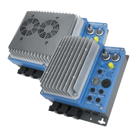
- Page 1 BU 0250 – en NORDAC LINK (SK 250E-FDS series) Users Manual for Frequency Inverters as Field Distributors...
- Page 2 NORDAC LINK (SK 250E-FDS series) – Users Manual for Frequency Inverters as Field Distributors Read document and keep for future reference Read this document carefully prior to performing any work on or putting the device into operation. It is essential to read and observe the instructions in this document. They serve as the prerequisite for smooth and safe operation and the fulfilment of any warranty claims.
- Page 3 Version list Version list Title, Order number Device Remarks firmware Date version BU 0250, 6072502 / 2916 V 1.0 R0 First edition for pilot series inverters (field test) July 2016 BU 0250, 6072502 / 2817 V 1.1 R2 • Names of option slots for control elements changed to H1, H2 and H3 July 2017 •...
-
Page 4: Table 1: Version List Bu0250
NORDAC LINK (SK 250E-FDS series) – Users Manual for Frequency Inverters as Field Distributors Title, Order number Device Remarks firmware Date version BU 0250, 6072502 / 3919 V 1.3 R0 Including September 2019 • General corrections • Extension of the series with size 0 (0.37 kW and above) •... - Page 5 Any editing or amendment or other utilisation of the document is prohibited. Publisher Getriebebau NORD GmbH & Co. KG Getriebebau-Nord-Straße 1 • 22941 Bargteheide, Germany • http://www.nord.com Fon +49 (0) 45 32 / 289-0 • Fax +49 (0) 45 32 / 289-2253 Member of the NORD DRIVESYSTEMS Group BU 0250 en-1724...
- Page 6 NORDAC LINK (SK 250E-FDS series) – Users Manual for Frequency Inverters as Field Distributors BU 0250 en-1724...
-
Page 7: Table Of Contents
Table of Contents Table of Contents General ............................... 12 Overview ............................13 Delivery ............................14 Scope of delivery..........................15 Safety, installation and application information ................15 Warning and hazard information ...................... 20 1.5.1 Warning and hazard information on the product ..............20 1.5.2 Explanation of markings ..................... - Page 8 NORDAC LINK (SK 250E-FDS series) – Users Manual for Frequency Inverters as Field Distributors 4.5.3 Bus structure and topology ....................78 4.5.4 Commissioning ........................80 4.5.4.1 Connection 4.5.4.2 Displays 4.5.4.3 Configuration 4.5.4.4 Addressing 4.5.5 Certificate ........................... 83 Parameter ..............................84 Parameter overview .........................
- Page 9 Table of Contents Maintenance and servicing information ....................225 Maintenance information ........................ 225 Service notes ..........................226 Disposal ............................227 9.3.1 Disposal according to German law ................... 227 9.3.2 Disposal outside of Germany.................... 227 Abbreviations ..........................228 BU 0250 en-1724...
- Page 10 NORDAC LINK (SK 250E-FDS series) – Users Manual for Frequency Inverters as Field Distributors List of illustrations Figure 1: SK CU4 … optional modules as internal control terminals (example) ............ 65 Figure 2: Explanation of parameter description ..................... 90 Figure 3 Setpoint processing ..........................195 Figure 4: Flow chart: Process controller ......................
- Page 11 List of tables List of tables Table 1: Version list BU0250 ........................... 4 Table 2: Additional characteristics ......................... 13 Table 3: Warning and hazard information on the product ..................20 Table 4: Standards and approvals ......................... 22 Table 5: FAQ operational problems ........................191 Table 6: EMC comparison between EN 61800-3 and EN 55011 .................
-
Page 12: General
NORDAC LINK (SK 250E-FDS series) – Users Manual for Frequency Inverters as Field Distributors 1 General The devices have sensorless current vector control with a wide range of settings. In combination with suitable motor models, which always provide an optimised voltage/frequency ratio, all three-phase asynchronous motors that are suitable for inverter operation and permanently excited synchronous motors can be driven. -
Page 13: Overview
1 General 1.1 Overview This manual describes the total number of possible functions and configurations. Depending on the device type, the configuration and functions are limited. Basic characteristics • High starting torque and precise motor speed control by means of sensorless current vector control •... -
Page 14: Delivery
NORDAC LINK (SK 250E-FDS series) – Users Manual for Frequency Inverters as Field Distributors Depending on the configuration, the meaning of the individual LEDs, function or assignment of individual plug connectors or the function of control elements (e.g. switches) may differ. The possible combinations will be illustrated and explained in the course of this manual. -
Page 15: Scope Of Delivery
1 General 1.3 Scope of delivery NOTICE Defect in the device Use of impermissible accessories and options (e.g. also options for other inverter series) may result in defects of interconnected components. • Only use accessories and options which are explicitly intended for use with this device and stated in this manual. - Page 16 NORDAC LINK (SK 250E-FDS series) – Users Manual for Frequency Inverters as Field Distributors The device is operated with hazardous voltage. Dangerous voltage may be present at the supply lines, contact strips and PCBs of all connecting terminals (e.g. mains input, motor connection), even if the device is not working or the motor is not rotating (e.g.
- Page 17 1 General 2. Qualified specialist personnel Within the meaning of this basic safety information, qualified specialist personnel are persons who are familiar with the installation, assembly, commissioning and operation of the product and who have the qualifications appropriate to their work. In addition, the device and the accessories associated with it must only be installed and commissioned by a qualified electrician.
- Page 18 NORDAC LINK (SK 250E-FDS series) – Users Manual for Frequency Inverters as Field Distributors Installation and assembly The installation and cooling of the device must be implemented according to the regulations in the corresponding documentation. The permissible mechanical and climatic ambient conditions (see technical data in the manual for the device) must be complied with.
- Page 19 1 General Maintenance, repair and decommissioning Installation, maintenance and repair work must not be carried out unless the device has been disconnected from the voltage and at least 5 minutes have elapsed since the mains was switched off! (Due to charged capacitors, hazardous voltages may be present on the device for up to 5 minutes after being switched off from the mains).
-
Page 20: Warning And Hazard Information
NORDAC LINK (SK 250E-FDS series) – Users Manual for Frequency Inverters as Field Distributors 1.5 Warning and hazard information Under certain circumstances, hazardous situations may occur in association with the frequency inverter. In order to give explicit warning of possibly hazardous situations, clear warning and hazard information can be found on the device and in the relevant documentation. -
Page 21: Explanation Of Markings
1 General 1.5.2 Explanation of markings DANGER Indicates an immediate danger, which may result in death or very serious injury if it is not avoided. WARNING Indicates a dangerous situation, which may result in death or serious injury if it is not avoided. CAUTION Indicates a dangerous situation, which may result in minor injuries if it is not avoided. -
Page 22: Standards And Approvals
NORDAC LINK (SK 250E-FDS series) – Users Manual for Frequency Inverters as Field Distributors 1.6 Standards and approvals All devices across the entire series comply with the standards and directives listed below. Applied Approval Directive Certificates Label standards Low Voltage 2014/35/EU 2014/30/EU EN 61800-5-1... - Page 23 1 General Information Group fuse protection The devices can be protected as a group via one common fuse (see below for details). Pay attention to compliance with the total currents and the use of correct cables and cable cross-sections. If the device is mounted close to the motor, this also applies to the motor cables.
- Page 24 NORDAC LINK (SK 250E-FDS series) – Users Manual for Frequency Inverters as Field Distributors Size valid description 1 - 2 For 480V - for 3 “Suitable For Use On A Circuit Capable Of Delivering Not More Than ______ rms Symmetrical phase models Amperes, 500 (3-phase) Volts Max., When Protected by High-Interrupting Capacity, Current only:...
- Page 25 1 General Information Connector optional Cat. No. manufactured by rated voltage rated current Fuse size SCCR, RMS 09 12 003 3051 HARTING ELECTRIC 600 V 17 A (AWG 16) 65 kA (HAN Q3/0-M) GMBH & CO KG 21 A (AWG 14) 25 A (AWG 12) 09 12 003 3151 (HAN Q3/0-F)
-
Page 26: Type Code / Nomenclature
NORDAC LINK (SK 250E-FDS series) – Users Manual for Frequency Inverters as Field Distributors 1.7 Type code / nomenclature The type code of the device depicts the basic features. A unique identification of the device including all customer-specific features is only possible via the device’s order or serial number. 1.7.1 Name plate All of the information which is relevant for the device, including information for the identification of the device, can be obtained from the name plate. -
Page 27: Field Distribution Type Codes
1 General SCCR: 65 kA, 500 V, BCP Fuse Class RK5 or faster HARTING SCCR: 65 kA, 480 V, BCP CB SCCR: 20 kA, 500 V, BCP CB BCP Rating and further Short Circuit Rating see manual Suitable for group fusing SCCR Group Installation: same except BCP Fuse or CB rated max. - Page 28 NORDAC LINK (SK 250E-FDS series) – Users Manual for Frequency Inverters as Field Distributors Configuration code Meaning -AS-i Actuator-sensor interface with “AS-i” connector option -ASS Actuator-sensor interface with “ASS” connector option -AUX Actuator-sensor interface with “AUX” connector option -AXS Actuator-sensor interface with “AXS” connector option -BRI Integrated braking resistor -BWRN...
-
Page 29: Power-Size Assignment
1 General 1.8 Power-size assignment Mains/power assignment Size 3~ 380 – 500 V Size 0 0.37 kW Size 1 0.55 ... 3.0 kW Size 2 4.0 ... 7.5 kW 1.9 Version with protection class IP55, IP65 The frequency inverter of the field distributor series SK 250E-FDS meets the following IP protection class: •... -
Page 30: Assembly And Installation
NORDAC LINK (SK 250E-FDS series) – Users Manual for Frequency Inverters as Field Distributors 2 Assembly and installation No options can be retrofitted. All options must be recorded by NORD when ordering and before the production process. The customer must not open the device at any time and does not need to. The device is mounted by using mounting lugs that are freely accessible from the outside. - Page 31 2 Assembly and installation Sizes 0 and 1 BU 0250 en-1724...
-
Page 32: Option Slots And Equipment Versions
NORDAC LINK (SK 250E-FDS series) – Users Manual for Frequency Inverters as Field Distributors Size 2 External braking resistor The attachment increases the frequency inverter’s width (measurement “X“) by 44 mm. This applies to sizes 1 and 2. 2.2 Option slots and equipment versions The device is configured according to the customer specification. -
Page 33: Connection Level
2 Assembly and installation 2.2.1.1 Connection level Position: bottom The configuration and assignment of the power connections (mains and motor connections) depends on the customer's specification for the product. This also applies for the additional option slots for the signal connections. X1 = Power connection 1 …... -
Page 34: Control Level
NORDAC LINK (SK 250E-FDS series) – Users Manual for Frequency Inverters as Field Distributors 2.2.1.2 Control level Position: front The configuration and functions of the individual option slots are variable. They are directly influenced customer's specification, also indirectly dependent on the further features. The meaning of the LEDs which are assigned for each option slot is also dependent. -
Page 35: Configuration Variants
2 Assembly and installation 2.2.2 Configuration variants The field distribution frequency inverter is designed so that it can be configured according to the individual requirements of the drive application. Because of this, extensive interfaces are provided on the FI, which are exclusively implemented in the form of plug connectors. As with the equipment of the device, the arrangement of these interfaces also depends on the configuration of the FI and therefore differs greatly. -
Page 36: Configuration Of Option Slots Of The Control Level
NORDAC LINK (SK 250E-FDS series) – Users Manual for Frequency Inverters as Field Distributors 2.2.2.1 Configuration of option slots of the control level The option slots M1 to M8 are designed for M12 plug connectors. The device-relevant assignment of the connections or functions of the individual option slots is directly printed on the option slot. Option slot Option type Function... - Page 37 2 Assembly and installation The device’s control elements are located at the option slots H1 and H2. Different control elements can be selected. Depending on the selected combination, they can influence the functions of individual digital inputs. These functions are device-specific in the factory settings of the respective parameter.
- Page 38 NORDAC LINK (SK 250E-FDS series) – Users Manual for Frequency Inverters as Field Distributors Plug connections for M12 plug connectors Depending on the function, 5-pin M12 surface mounted plug connectors with coloured sockets or plug inserts are installed. The colours reflect the functional assignment of the plug connector and therefore enable easy identification on the FI.
-
Page 39: Configuration Of Option Slots On The Connection Level
2 Assembly and installation 2.2.2.2 Configuration of option slots on the connection level The connection level of the field distribution frequency inverter is divided into 2 areas. Electric shock at X2 DANGER An optional mains connection outlet (LA) on option slot X2 can also not be switched off with a repair and maintenance switch (option slot H3). - Page 40 NORDAC LINK (SK 250E-FDS series) – Users Manual for Frequency Inverters as Field Distributors Option slot Plug connector type Function Contact assignment 1 L1 3 L3 4 PE 2.5 mm / 16 A No function Option slot not used b HARTING Q4/2+ Mains connection (socket) (outlet)
- Page 41 2 Assembly and installation a HARTING Q8/0+ Motor connection 1 (socket) (outlet) 4 mm / 16 A 4 BR- 6 BR+ 7 V b AMPHENOL P30539 Motor connection 1 (socket) (outlet) D PE E MB1 F TH TH1 H nc. L MB2 a HARTING Q2/0+ Brake resistor...
-
Page 42: Figure 1: Sk Cu4
NORDAC LINK (SK 250E-FDS series) – Users Manual for Frequency Inverters as Field Distributors Area 2, option slots Z1 to Z4 The option slots M1 to M8 are designed for M12 plug connectors. No fixed functions are allocated to the option slots. -
Page 43: Configuration Of The Option Slot For The Maintenance Switch Level
2 Assembly and installation Function Plug connector Option slot Contact Contact assignment diagram Colour SIN-/COS 24 V (SIN-/COS encoder) Socket, A-coded SI / Clock (Safe input/clock) Socket, A-coded The housings of the plug connectors are internally wired to PE. 2.2.2.3 Configuration of the option slot for the maintenance switch level Electric shock at X2 DANGER... -
Page 44: Electrical Connection
NORDAC LINK (SK 250E-FDS series) – Users Manual for Frequency Inverters as Field Distributors 2.3 Electrical Connection WARNING Electric shock Dangerous voltages may be present at the plug contacts for the power connections (e.g. mains cable, motor cable) even when the device is not in operation. •... -
Page 45: Wiring Guidelines
2 Assembly and installation 2.3.1 Wiring guidelines The devices have been developed for use in an industrial environment. In this environment, electromagnetic interference can affect the device. In general, correct installation ensures safe and problem-free operation. To meet the limiting values of the EMC directives, the following instructions should be complied with. -
Page 46: Electrical Connection Of Power Unit
NORDAC LINK (SK 250E-FDS series) – Users Manual for Frequency Inverters as Field Distributors 2.3.2 Electrical connection of power unit NOTICE EMC interference to the environment This device produces high-frequency interference, which may make additional suppression measures necessary in domestic environments 8.3 "Electromagnetic compatibility (EMC)". The use of shielded motor cables is essential in order to maintain the specified radio interference suppression level. -
Page 47: Daisy Chain Connection
2 Assembly and installation NOTICE Operation in IT networks If a mains fault (earth fault) occurs in an IT network, the link circuit of a connected frequency inverter may become charged, even if it is switched off. This results in destruction of the link circuit capacitors due to overcharging. -
Page 48: Motor Cable
NORDAC LINK (SK 250E-FDS series) – Users Manual for Frequency Inverters as Field Distributors WARNING Hazardous voltage at the contacts of the mains output socket Danger of electric shock, short circuit or earth fault if water or cleaning agents enter. •... - Page 49 2 Assembly and installation SK 2xxE-FDS-… Resistance Max. continuous Energy power / consumption limitation …370-340- to …301-340- 100 W / 25% 1.0 kWs 400 Ω …401-340- to …751-340- 200 Ω 200 W / 25% 2.0 kWs Maximum once within 10 s To prevent impermissibly high heating of the device, the continuous power is limited to 1/4 of the braking resistor’s rated power.
-
Page 50: Electromechanical Brake
NORDAC LINK (SK 250E-FDS series) – Users Manual for Frequency Inverters as Field Distributors Information External braking resistor or daisy chain wiring Connection of an external braking resistor to option slot X2 prevents the possibility of daisy chain wiring (looping of the mains voltage). 2.3.2.5 Electromechanical brake For the control of an electromechanical brake, the device generates an output voltage provided at the... -
Page 51: Electrical Connection Of The Control Unit
2 Assembly and installation 2.3.3 Electrical connection of the control unit Connection of the control cables is made exclusively via M12 plug connectors. The plug connectors are permanently installed at the factory. These enable the use of straight connectors, and at option slots M1 to M8 angled (encapsulated) cable plug connectors. - Page 52 NORDAC LINK (SK 250E-FDS series) – Users Manual for Frequency Inverters as Field Distributors Information Response time of digital inputs The response time to a digital signal is approx. 4 – 5 ms and consists of the following: Scan time 1 ms Signal stability check 3 ms...
-
Page 53: Control Connection Details
2 Assembly and installation 2.3.3.1 Control connection details Meaning, Functions Description / Technical data Contact Parameter (designation) Meaning Function of factory setting Digital outputs Signalling of the operating statuses of the FI according to EN 61131-2 Maximum load 50 mA 24 V DC With inductive loads: Provide protection via free-wheeling diode! - Page 54 NORDAC LINK (SK 250E-FDS series) – Users Manual for Frequency Inverters as Field Distributors Control voltage source Control voltage from the device e.g. for supply of accessories 24 V DC ± 25%, short-circuit protected Maximum load VO / 24V Voltage output The 24 Vout at M1-M8 are limited to 100 mA each in groups of two.
-
Page 55: Basic Control Unit Configuration
2 Assembly and installation Communication Connection of the FI to various communication tools interface 24 VDC ± 20% RS485 (for connecting a parametrisation box) 9600 … 38400 Baud Terminating resistor (1 kΩ) fixed RS232 (for connection to a PC( NORDCON)) 9600 …... -
Page 56: Colour And Contact Assignment For Incremental Encoder (Htl)
NORDAC LINK (SK 250E-FDS series) – Users Manual for Frequency Inverters as Field Distributors 2.4 Colour and contact assignment for incremental encoder (HTL) Wire colours, Function SK 2xxE-FDS assignment for incremental encoders 24 V supply Brown / green 24V (VO) 0 V supply White / green 0V (GND) - Page 57 2 Assembly and installation Contact assignment Function M12 socket, A-coded Colour Encoder 12 V Data + Data - – Black connection Note the current consumption of the encoder (normally up to 150 mA) and the permissible load on the control voltage source. For use of the encoder, parameters (P300) or (P600) must be activated according to requirements (speed feedback / servo mode or positioning).
-
Page 58: Display, Operation And Options
NORDAC LINK (SK 250E-FDS series) – Users Manual for Frequency Inverters as Field Distributors 3 Display, operation and options WARNING Electric shock Touching the circuit board below the transparent screw cap on option slot E1 can result in an electric shock which may cause serious or fatal injury. - Page 59 3 Display, operation and options M1 to M8 If initiators or actuators are used, the LEDs indicate the corresponding signal • statuses (high/low). (Yellow colour) The options slots M1, M3, M5 and M7 are generally intended for double occupancy. – Lower LED: Signal status first input or output (e.g. DIN1) –...
- Page 60 NORDAC LINK (SK 250E-FDS series) – Users Manual for Frequency Inverters as Field Distributors Diagnostic LEDs Colour Description Signal status Meaning Dual Device status Device is not ready for operation, Red/green • no mains or control voltage Green On Device is enabled (inverter is working) Flashing 0.5 Hz Device is ready to switch-on, but not...
- Page 61 3 Display, operation and options Colour Description Signal status Meaning Dual CU4 status Module (SK CU4-…) not ready for operation, Red/green • no control voltage • no SK CU4-… module installed Note: If a type SK CU4-IOE module is installed, the LED also remains off.
- Page 62 NORDAC LINK (SK 250E-FDS series) – Users Manual for Frequency Inverters as Field Distributors Colour Description Signal status Meaning Green System bus No process data communication State Flashing 4 Hz „BUS warning“ Process data communication active • Receipt of at least 1 telegram / s •...
-
Page 63: Control And Parametrisation Options
3 Display, operation and options 3.2 Control and parametrisation options There are different control options available, installed on the option slots H1 and H2. The required control options and their functions must be selected upon ordering or during the configuration process (... -
Page 64: Connection Of Multiple Devices To One Parametrisation Tool
NORDAC LINK (SK 250E-FDS series) – Users Manual for Frequency Inverters as Field Distributors 3.2.1 Connection of multiple devices to one parametrisation tool In principle it is possible to access several frequency inverters via the ParameterBox or the NORDCON software. In the following example, communication is made via the parameterisation tool, by tunnelling the protocols of the individual devices (max. -
Page 65: Optional Modules
3 Display, operation and options 3.3 Optional modules 3.3.1 SK CU4-… optional modules As so-called internal control terminals, SK CU4- optional modules enable the scope of functions of the FIs to be extended without changing the size. The FI provides two slots for installation of the corresponding modules. -
Page 66: Optional Plug-In Eeprom
NORDAC LINK (SK 250E-FDS series) – Users Manual for Frequency Inverters as Field Distributors 3.3.2 Optional plug-in EEPROM The plug-in EEPROM (equipment code -EEP) is operated in parallel with the frequency inverter EEPROM and is primarily used for data backup. In the event of a defect in the frequency inverter the data (parameter data, PLC program) of the defective frequency inverter can be copied to an identical replacement device to minimise downtime. - Page 67 3 Display, operation and options Disconnecting the frequency inverter from the low voltage and checking the absence of voltage in the device Removing the EEPROM Remove the transparent screw cap. Pull off the EEPROM Continue with step 5 if the frequency inverter is to be operated without a plug-in EEPROM.
- Page 68 NORDAC LINK (SK 250E-FDS series) – Users Manual for Frequency Inverters as Field Distributors Function The EEPROM is equipped with a 3-stage DIP switch. This can be used to set the function of the EEPROM. The DIP switch can be adjusted using a small slotted screwdriver.
-
Page 69: Commissioning
4 Commissioning 4 Commissioning WARNING Unexpected movement Connection of the supply voltage may directly or indirectly set the device into motion. This can cause unexpected movement of the drive and the attached machine, which may result in serious or fatal injuries and/or material damage. -
Page 70: Factory Settings
NORDAC LINK (SK 250E-FDS series) – Users Manual for Frequency Inverters as Field Distributors 4.2 Factory settings All frequency inverters supplied by Getriebebau NORD are pre-programmed with the default setting for standard applications with 4-pole three-phase standard motors (same power and voltage). For use with motors with other powers or number of poles, the data from the name plate of the motor must be entered into the parameters P201...P207 under the menu item >Motor data<. -
Page 71: Selecting The Operating Mode For Motor Control
4 Commissioning 4.3 Selecting the operating mode for motor control The frequency inverter is able to control motors with efficiency classes IE1 to IE5+. Our motors are designed as asynchronous motors in efficiency classes IE1 to IE3, and IE4 and IE5+ motors are designed as synchronous motors. - Page 72 NORDAC LINK (SK 250E-FDS series) – Users Manual for Frequency Inverters as Field Distributors • CFC open-loop mode (P300 = 2) The CFC mode is also possible in the open-loop method, i.e. in operation without encoder. Speed and position detection are determined using “observers” from measuring and actuating values. The prerequisite for this operating mode is a precise setting of the current and speed controller.
-
Page 73: Overview Of Control Parameter Settings
4 Commissioning 4.3.2 Overview of control parameter settings The following provides an overview of all parameters which are of importance, depending on the selected operating mode. Among other things, a distinction is made between "relevant" and "important", which provides an indication of the required precision of the particular parameter setting. However, in principle, the more precisely the setting is made, the more exact the control, so that higher values for dynamics and precision are possible for the operation of the drive unit. -
Page 74: Motor Control Commissioning Steps
NORDAC LINK (SK 250E-FDS series) – Users Manual for Frequency Inverters as Field Distributors 4.3.3 Motor control commissioning steps The main commissioning steps are mentioned below in their ideal order. The correct assignment of the frequency inverter/motor and the mains voltage selection are assumed. Detailed information, especially for optimisation of the current, speed and position controllers of asynchronous motors is described in the guide “Controller Optimisation”... -
Page 75: As Interface (As-I)
4 Commissioning 4.5 AS Interface (AS-i) Frequency inverters from Getriebebau NORD GmbH & Co. KG that feature an AS-Interface support the ASi-3 version of the AS protocol. This section is only relevant for device of type SK 270E-FDS / SK 280E-FDS. 4.5.1 The bus system General information The Actuator Sensor Interface (AS-Interface) is a bus system for the lower field bus level. - Page 76 NORDAC LINK (SK 250E-FDS series) – Users Manual for Frequency Inverters as Field Distributors Supplement to plug connector option ”-ASI“ or “-AUX” The FI is designed as a double slave and supports the CTT2 protocol. For this, two AS interface slaves (1st slave and 2nd slave) are integrated into the device.
-
Page 77: Features And Technical Data
4 Commissioning 4.5.2 Features and technical data The device can be directly integrated in an AS interface network is parametrised in its factory settings so that the most frequently used AS-i functionality is available immediately. Only adaptations for application-specific functions of the device or the bus system, the addressing and proper connection of the supply, BUS, sensor and actuator cables need to be carried out. -
Page 78: Bus Structure And Topology
NORDAC LINK (SK 250E-FDS series) – Users Manual for Frequency Inverters as Field Distributors Technical AS-Interface data Option slot M8: Device with connector option … Designation … “-ASI” … “-ASS” … “-AUX“ … “-AXS“ ... “-AXB“ AS-i supply 24 – 31.6 V DC, 24 –... - Page 79 4 Commissioning Controller / automation unit AS interface power unit AS interface master AS interface yellow cable 24 V auxiliary supply, black cable 24 V power supply for auxiliary energy AS-i AS-i AS interface AS interface Slave Slave observe max. power load Sensors Actuators...
-
Page 80: Commissioning
NORDAC LINK (SK 250E-FDS series) – Users Manual for Frequency Inverters as Field Distributors 4.5.4 Commissioning 4.5.4.1 Connection 1. The connection of the AS-Interface cable (yellow) is established via the “-ASI“, “-AUX“, “-AXS“, “-ASS“ or -AXB plug connector on option slot M8. 2. -
Page 81: Configuration
4 Commissioning 4.5.4.3 Configuration The most important functions are assigned via the parameters (P480) and (P481). Bus I/O bits WARNING Unexpected movement due to automatic starting In the event of a fault (communication interrupted or bus cable disconnection) the device automatically switches off, since the device enable is no longer present. -
Page 82: Addressing
NORDAC LINK (SK 250E-FDS series) – Users Manual for Frequency Inverters as Field Distributors 4.5.4.4 Addressing Addressing with plug connector option ”-ASI“ or “-AUX” In order to use the device in an AS-I network, both of the slaves (1st slave and 2nd slave) which are installed in this device must be assigned a unique address. -
Page 83: Certificate
4 Commissioning Version 1 Using addressing device which equipped with an M12 connector for AS-i AS-i AS-i connecting to the AS-i bus, you can Power Master Power incorporate yourself into a the AS interface network via an appropriate access. The prerequisite for this is that the AS interface master can be switched off. -
Page 84: Parameter
NORDAC LINK (SK 250E-FDS series) – Users Manual for Frequency Inverters as Field Distributors 5 Parameter WARNING Unexpected movement Connection of the supply voltage may directly or indirectly set the device into motion. This can cause unexpected movement of the drive and the attached machine, which may result in serious or fatal injuries and/or material damage. - Page 85 5 Parameter WARNING Unexpected movement due to overload In case of overload of the drive, there is a risk that the motor will “break down” (sudden loss of torque). An overload may be caused e.g. by inadequate dimensioning of the drive unit or by the occurrence of sudden peak loads.
- Page 86 NORDAC LINK (SK 250E-FDS series) – Users Manual for Frequency Inverters as Field Distributors The individual parameters are combined in functional groups. The first digit of the parameter number indicates the assignment to a menu group: Menu group Master function Operating displays (P0--) Display of parameters and operational values...
-
Page 87: Parameter Overview
5 Parameter 5.1 Parameter overview Operating displays P000 Operating display P001 Selection of display value P002 Display factor P003 Display factor Basic parameters P100 Parameter set P101 Copy parameter set P102 Acceleration time P103 Deceleration time P104 Minimum frequency P105 Maximum frequency P106 Ramp smoothing P107 Brake response time... - Page 88 NORDAC LINK (SK 250E-FDS series) – Users Manual for Frequency Inverters as Field Distributors Control terminals P400 Function Setpoint inputs P401 Analog input mode P402 Adjustment: 0% P403 Adjustment: 100% P404 Analog input filter P410 Min. freq. Auxiliary setpoint P411 Max. Freq. Auxiliary P412 Process ctrl.
- Page 89 5 Parameter Information P700 Present Operating P701 Last fault P702 Freq. last error status P703 Current. last error P704 Volt. last error P705 Dc.lnk volt. last er. P706 P set last error P707 Software version P708 Status of digital in. P709 Analogue input voltage P710 Analogue output volt.
-
Page 90: Operating Displays
NORDAC LINK (SK 250E-FDS series) – Users Manual for Frequency Inverters as Field Distributors P000 Operating para. disp. (parameter number) (parameter name) Setting range Display of the typical display format, possible setting range and number of decimal places or display range Arrays [-01] If parameters have a substructure in several arrays, this is shown here. - Page 91 5 Parameter P003 Supervisor-Code Setting range 0 … 9999 Factory setting { 1 } Description The scope of the visible parameters can be influenced by setting the supervisor code. Note Display via NORDCON If parameterisation is carried out with the NORDCON software, the settings 4 ... 9999 the settings are as for the 0 setting.
-
Page 92: Basic Parameters
NORDAC LINK (SK 250E-FDS series) – Users Manual for Frequency Inverters as Field Distributors 5.1.2 Basic parameters P100 Parameter set Setting range 0 … 3 Factory setting { 0 } Description Selection of the parameters sets to be parameterised. Four parameter sets are available. - Page 93 5 Parameter P103 Deceleration time Setting range 0.00 … 320.00 s Factory setting { 2.00 } Description The deceleration time is the time corresponding to the linear frequency reduction from the set maximum frequency P105 to 0 Hz. If a current setpoint < 100% is being used, the deceleration time reduces accordingly.
- Page 94 NORDAC LINK (SK 250E-FDS series) – Users Manual for Frequency Inverters as Field Distributors P106 Ramp smoothing Setting range 0 … 100% Factory setting { 0 } Description This parameter enables smoothing of the acceleration and deceleration ramps. This is necessary for applications where gentle, but dynamic speed change is important.
- Page 95 5 Parameter Information Brake control To control the electromechanical brake (especially for lifting gears), the relevant connection on the frequency inverter must be used, if available. The absolute minimum frequency (P505) should never be less than 2.0 Hz. Information Torque limitation during active setpoint delay (P107/P114) During an active setpoint delay, the torque is limited to a maximum of 160% of the rated torque.
- Page 96 NORDAC LINK (SK 250E-FDS series) – Users Manual for Frequency Inverters as Field Distributors P108 Switch-off mode Setting range 0 ... 13 Factory setting { 1 } Description This parameter determines the way in which the output frequency is reduced after "Blocking"...
- Page 97 5 Parameter P109 DC brake current Setting range 0 … 250 % Factory setting { 100 } Description Current setting for the functions of DC current braking (P108 = 3) and combined braking (P108 = 5). The correct setting value depends on the mechanical load and the required deceleration time.
- Page 98 NORDAC LINK (SK 250E-FDS series) – Users Manual for Frequency Inverters as Field Distributors P112 Torque current limit Setting range 25 … 400% / 401 Factory setting { 401 } Description ASM With this parameter, a limit value for the torque-generating current can be set. This can prevent mechanical overloading of the drive.
- Page 99 5 Parameter P114 Brake delay off Setting range 0.00 … 2.50 s Factory setting { 0.00 } Description Electromagnetic brakes have a delayed response time for their release, which depends on physical factors. This can lead to the motor running while the brake is still applied, which will cause the FI to switch off with an overcurrent message.
-
Page 100: Motor Data / Characteristic Curve Parameters
NORDAC LINK (SK 250E-FDS series) – Users Manual for Frequency Inverters as Field Distributors 5.1.3 Motor data / characteristic curve parameters P200 Motor list Setting range 0 … 148 Factory setting { 0 } Description The factory settings for the motor data can be edited with this parameter. A 4-pole IE1 asynchronous standard motor is set at the factory in parameters P201 …... - Page 101 5 Parameter 0.12kW 115V 1.10 kW 230 V 90T1/4 2.20 kW 400 V 90T1/4 0.18kW 115V 1.10 kW 230 V 80T1/4 3.00 kW 230 V 100T5/4 0.25kW 115V 1.10 kW 400 V 80T1/4 3.00 kW 230 V 100T2/4 0.37kW 115V 1.50 kW 230 V 90T3/4 3.00 kW 400 V 100T2/4 0.55kW 115V...
- Page 102 NORDAC LINK (SK 250E-FDS series) – Users Manual for Frequency Inverters as Field Distributors P206 Cos phi Setting range 0.50 … 0.98 Factory setting The default setting depends on the nominal power of the FI. Description The motor cos ϕ is a decisive parameter for current vector control. P207 Star Delta con.
- Page 103 5 Parameter P210 Static boost Setting range 0 ... 400% Factory setting { 100 } Description The static boost affects the current which generates the magnetic field. This corresponds to the no-load current of the respective motor and therefore does not depend on the load. The no-load current is calculated using the motor data.
- Page 104 NORDAC LINK (SK 250E-FDS series) – Users Manual for Frequency Inverters as Field Distributors P213 ISD ctrl. loop gain Setting range 25 ... 400% Factory setting { 100 } Description “ISD ctrl. loop gain”. This parameter influences the dynamics of the FI current vector control (ISD control).
- Page 105 5 Parameter P217 Oscillation damping Setting range 0 ... 400% Factory setting { 10 } Description The parameter is a measure of the damping power. Oscillations caused by resonance under no-load conditions can be suppressed with oscillation damping. For oscillation damping, the oscillation component is filtered out of the torque current by means of a high pass filter.
- Page 106 NORDAC LINK (SK 250E-FDS series) – Users Manual for Frequency Inverters as Field Distributors P219 Auto.magn.adjustment Setting range 25 ... 100% / 101 Factory setting { 100 } Description “Automatic flux optimisation”. With this parameter, the magnetic flux of the motor can be automatically matched to the motor load, so that the energy consumption is reduced to the amount which is actually required.
- Page 107 5 Parameter Information If the mains voltage is not connected (X1) the following parameter shows the value 0 and not the actual correct operating value. P220 Par.-identification Setting range 0 ... 2 Factory setting { 0 } Description “Parameter identification”. For devices with an output up to 7.5 KW, the motor data is determined automatically by the device via this parameter.
- Page 108 NORDAC LINK (SK 250E-FDS series) – Users Manual for Frequency Inverters as Field Distributors P240 EMF voltage PMSM Setting range 0 … 800 V Factory setting The default setting depends on the nominal power of the FI. Description The EMF voltage PMSM describes the mutual induction voltage of the motor. The value to be set can be found on the data sheet for the motor or on the name plate and is scaled to 1000 rpm.
- Page 109 5 Parameter P241 Inductivity PMSM Setting range 0.1 … 200.0 mH Arrays [-01] = [-02] = [-03] = unsaturated Ld [-04] = unsaturated Lq [-05] = saturated Ld [-06] = saturated Lq Factory setting The default setting depends on the nominal power of the FI. Description The stator inductivity of the d or q component of a permanently excited synchronous motor (PMSM).
- Page 110 NORDAC LINK (SK 250E-FDS series) – Users Manual for Frequency Inverters as Field Distributors P247 Switch freq VFC PMSM Setting range 1 ... 100% Factory setting { 25 } Description “Switchover frequency VFC PMSM”. In order to immediately provide a minimum amount of torque in case of spontaneous load changes, and in particular for small frequencies, in VFC mode the setpoint of I (excitation current) is controlled depending on the...
-
Page 111: Speed Control
5 Parameter 5.1.4 Speed control In connection with an HTL incremental encoder, a closed-loop speed control can be set up via the FI’s digital inputs 2 and 3. Alternatively, the incremental encoder signal can also be used for other purposes. The required function must then be selected in parameter P325 . - Page 112 NORDAC LINK (SK 250E-FDS series) – Users Manual for Frequency Inverters as Field Distributors P301 Incremental encoder Setting range 0 … 19 Factory setting { 6 } Description “Encoder resolution”. Input of the pulse count per rotation of the connected incremental encoder.
- Page 113 5 Parameter P313 Torque curr. ctrl. I Setting range 0 … 800% ms Factory setting { 50 } Description I component of the torque current controller (see P312 “Torque curr. ctrl. P”). P314 Torq curr ctrl limit Setting range 0 … 400 V Factory setting { 400 } Description...
- Page 114 NORDAC LINK (SK 250E-FDS series) – Users Manual for Frequency Inverters as Field Distributors P319 I-Weak Setting range 0 … 800% ms Factory setting { 20 } Description Only affects the field weakening range (see P318 “P-Weak”). P320 Weak border Setting range 0 …...
- Page 115 5 Parameter P326 Ratio encoder Setting range 0.01 … 100.00 Factory setting { 1.00 } Description “Ratio encoder”. If the incremental encoder is not mounted directly onto the motor shaft, then the respectively correct ratio of motor speed to encoder speed must be set. Motor speed P236= Encoder speed...
- Page 116 NORDAC LINK (SK 250E-FDS series) – Users Manual for Frequency Inverters as Field Distributors P330 Ident startrotor pos Setting range 0 … 6 Factory setting { 1 } Description “Rotor starting position detection “. Selection of the method for determination of the starting position of the rotor (initial value of the rotor position) of a PMSM (Permanent Magnet Synchronous Motor).
- Page 117 5 Parameter P331 Switch over freq. Setting range 5.0 ... 100.0% Factory setting { 15.0 } Description “Switchover frequency CFC open-loop”: For P300 = 2: Definition of the frequency above which, in operation without encoder, the control method is activated according to P300. Note •...
- Page 118 NORDAC LINK (SK 250E-FDS series) – Users Manual for Frequency Inverters as Field Distributors P334 Encoder offset PMSM Setting range -0.500 ... 0.500 rev Factory setting { 0.000 } Description Evaluation of the zero track is necessary for closed-loop operation of PMSMs (Permanent Magnet Synchronous Motors) with incremental encoders.
- Page 119 5 Parameter P336 Mode Rotorpos ident Setting range 0 ... 2 Factory setting { 0 } Description “Mode of identification of the starting conditions”. This parameter has a double function. Function 1: Definition of the mode for the rotor position identification of a synchronous motor (PMSM).
- Page 120 NORDAC LINK (SK 250E-FDS series) – Users Manual for Frequency Inverters as Field Distributors P351 PLC set val. select. Setting range 0 … 3 Factory setting { 0 } Description Selection of the source for the control word (CTW) and the main setpoint (MSW) with active PLC functionality (P350 = 1).
- Page 121 5 Parameter P353 Bus status via PLC Setting range 0 … 3 Factory setting { 0 } Description This parameter decides whether the control word for the master function and the status word of the frequency inverter are further processed by the PLC. Setting values Value Meaning...
-
Page 122: Control Terminals
NORDAC LINK (SK 250E-FDS series) – Users Manual for Frequency Inverters as Field Distributors 5.1.5 Control terminals P400 Setpoint I/P Funct Setting range 0 … 36 Arrays [-01] = Analog input 1 Analogue input 1 of the frequency inverter [-02] = Analog input 2 Analogue input 2 of the frequency inverter [-03] =... - Page 123 5 Parameter “Switching-off torque current limit”, depends on parameter P112. Torqu.curr.limit off This value corresponds to 100% setpoint. Achieving the set limit value results in switch-off with error code E12.3. Current limit “Limiting current limit”, depends on parameter P536. This value corresponds to 100% setpoint.
- Page 124 NORDAC LINK (SK 250E-FDS series) – Users Manual for Frequency Inverters as Field Distributors P401 Mode analog in Setting range 0 … 5 AIN1 of the first I/O extension Arrays [-01] = Ext. Analogue in 1 [-02] = Ext. Analogue in 2 AIN2 of the first I/O extension Ext.AI 1 2.IOE “External analogue input 1, 2nd IOE“, AIN1 of the...
- Page 125 5 Parameter -10V - 10V If a setpoint smaller than the programmed “adjustment 0% “(P402) is present, this may cause a change in direction rotation. This allows rotation direction reversal using a simple voltage source and potentiometer. E.g. internal setpoint with reversal of direction of rotation: P402 = 50 %, P104 = 0 Hz, potentiometer 0 …...
- Page 126 NORDAC LINK (SK 250E-FDS series) – Users Manual for Frequency Inverters as Field Distributors Information Use of DIP switches If the device was ordered with an IO extension SK CU4-IOE, the DIP switches on the IO extension are configured according to the customer’s requirements on delivery. Subsequent changes to the settings are no longer possible after delivery.
- Page 127 5 Parameter P404 Analog input filter Setting range 10 ... 400 ms Arrays [-01] = Analog input 1 Analogue input 1 of the frequency inverter [-02] = Analog input 2 Analogue input 2 of the frequency inverter Factory setting All { 100 } Description Adjustable digital low-pass filter for the analogue signal.
- Page 128 NORDAC LINK (SK 250E-FDS series) – Users Manual for Frequency Inverters as Field Distributors Uh, j a P411 Max. freq. a-in 1/2 Setting range -400.0 ... 400.0 Hz Factory setting { 50.0 } Description "Maximum frequency auxiliary setpoints". The maximum frequency that can act on the setpoint via the auxiliary setpoints.
- Page 129 5 Parameter P417 Offset analog output Setting range -10.0 ... 10.0 V [-01] = IOE-1 IOE”. Analogue “External analogue output of the 1 output of the first IO extension [-02] = IOE-2 “External analogue output of the 2 IOE”. Analogue output of the second IO extension Only in connection with SK CU4-IOE or SK TU4-IOE Scope of application...
- Page 130 NORDAC LINK (SK 250E-FDS series) – Users Manual for Frequency Inverters as Field Distributors Torque [%] The current torque calculated by the device. (100% = nominal motor torque) Field [%] The current field in the motor calculated by the device. Actual frequency ±...
- Page 131 5 Parameter P420 Digital inputs Setting range 0 … 80 Arrays [-01] = Digital input 1 Digital input 1 (DIN1) integrated into the device [-02] = Digital input 2 Digital input 2 (DIN2) integrated into the device [-03] = Digital input 3 Digital input 3 (DIN3) integrated into the device [-04] = Digital input 4...
- Page 132 NORDAC LINK (SK 250E-FDS series) – Users Manual for Frequency Inverters as Field Distributors Phase seq. reversal Causes the rotating field to change direction (combined with High enable “right” or “left”). The frequency from P465 [-01] is added to the current setpoint. Fixed frequency 1 High Fixed frequency 2...
- Page 133 5 Parameter Note The functions { 26 } … { 27 } can only be used for digital input 3 (P420 [-03]). With this setting, pulses which are proportional to an analogue signal can be evaluated using DIN 3. The function of this signal Analog fct.
- Page 134 NORDAC LINK (SK 250E-FDS series) – Users Manual for Frequency Inverters as Field Distributors Dig.out man/auto set Set digital output 1: manually or via the set function in (P434) High Dig.out manual set Set digital output 1: manually High Speed meas.with ini. Simple speed measurement (pulse measurement) with initiator Pulses Evacuation mode...
- Page 135 5 Parameter P425 Function PTC input Setting range 0 … 1 Factory setting { 1 } Description A connected PTC resistor is evaluated by the device. This function must be disabled if no PTC resistor is connected. Otherwise, the device will enter a fault state with an overtemperature message (E2.0).
- Page 136 NORDAC LINK (SK 250E-FDS series) – Users Manual for Frequency Inverters as Field Distributors P428 Automatic starting Setting range 0 … 1 Factory setting { 0 } Description WARNING! Danger of injury due to unexpected movements of the drive. Switch-on after an earth fault/short-circuit.
- Page 137 5 Parameter nomenclature”) can directly control a typical motor brake ( Section 2.3.2.4 “Electromechanical brake”. A mechanical brake can be directly switched with AC. (Note the technical specification of the relay contact!) Inverter is working The closed relay contact indicates voltage at the inverter High output (U –...
- Page 138 NORDAC LINK (SK 250E-FDS series) – Users Manual for Frequency Inverters as Field Distributors P435 Dig. out scaling Setting range -400 … 400% [-01] = Digital out 1 Digital output 1 of the frequency inverter [-02] = Digital out 2 Digital output 2 of the frequency inverter Factory setting All { 100 }...
- Page 139 5 Parameter P465 Fixed freq. Array Setting range -400.0 … 400.0 Hz Arrays [-01] = Fixed frequency array 1 [-02] = Fixed frequency array 2 … … [-15] = Fixed frequency array 15 Factory setting [-01] = { 5.0 } [-02] = { 10.0 } [-03] = { 20.0 } [-04] = { 35.0 }...
- Page 140 NORDAC LINK (SK 250E-FDS series) – Users Manual for Frequency Inverters as Field Distributors P475 Delay on/off switch Setting range -30,000 ... 30,000 s Arrays [-01] = Digital input 1 Digital input 1 (DI1) integrated into the device [-02] = Digital input 2 Digital input 2 (DI2) integrated into the device [-03] =...
- Page 141 5 Parameter P481 Funct-BusIO Out Bits Setting range 0 … 40 Arrays [-01] = Bus / AS-i Dig Out1 BusIO Out Bit 0 + AS-i 1 [-02] = Bus / AS-i Dig Out2 BusIO Out Bit 1 + AS-i 2 [-03] = Bus / AS-i Dig Out3 BusIO Out Bit 2 + AS-i 3...
- Page 142 NORDAC LINK (SK 250E-FDS series) – Users Manual for Frequency Inverters as Field Distributors P482 Norm. BusIO Out Bits Setting range -400 … 400% Arrays [-01] = Bus / AS-i Dig Out1 BusIO Out Bit 0 + AS-i 1 [-02] = Bus / AS-i Dig Out2 BusIO Out Bit 1 + AS-i 2 [-03] =...
- Page 143 5 Parameter P483 Hyst. BusIO Out Bits Setting range 1 … 100% Arrays [-01] = Bus / AS-i Dig Out1 BusIO Out Bit 0 + AS-i 1 [-02] = Bus / AS-i Dig Out2 BusIO Out Bit 1 + AS-i 2 [-03] = Bus / AS-i Dig Out3 BusIO Out Bit 2 + AS-i 3...
-
Page 144: Additional Parameters
NORDAC LINK (SK 250E-FDS series) – Users Manual for Frequency Inverters as Field Distributors 5.1.6 Additional parameters P501 Inverter name Setting range A … Z (char) Arrays [-01] … [-20] Factory setting { 0 } Description Free input of a designation (name) for the device (max. 20 characters). With this, the frequency inverter can be uniquely identified for setting with NORDCON software or within a network. - Page 145 5 Parameter P503 Leading func. output Setting range 0 ... 3 Factory setting { 0 } Description For master-slave applications this parameter specifies on which bus system the master transmits the control word and the master values P502 for the slave. On the slave, parameters P509, P510, P546 define the source from which the slave obtains the control word and the master values from the master and how these are to be processed by the slave.
- Page 146 NORDAC LINK (SK 250E-FDS series) – Users Manual for Frequency Inverters as Field Distributors P504 Pulse frequency Setting range 4.0 ... 16.0 kHz / 16.1 ... 16.4 Factory setting { 6.0 } Description With this parameter, the internal pulse frequency for controlling the power section can be changed.
- Page 147 5 Parameter P505 Absolute mini. freq. Setting range 0.0 … 10.0 Hz Factory setting { 2.0 } Description “Absolute minimum frequency”. Specifies the frequency value that cannot be undershot by the FI. If the setpoint becomes smaller than the absolute minimum frequency, the FI switches off or changes to 0.0 Hz.
- Page 148 NORDAC LINK (SK 250E-FDS series) – Users Manual for Frequency Inverters as Field Distributors P509 Control word source Setting range 0 ... 5 Factory setting { 0 } Description Selection of the interface via which the frequency inverter receives its control word (for enabling, direction of rotation, etc.).
- Page 149 5 Parameter P510 Source Setpoints Setting range 0 ... 5 Arrays Selection of the setpoint source. [-01] = Source main setpoint [-02] = Source 2nd setpoint Factory setting all { 0 } Description Selection of the interface, from which the frequency inverter receives its setpoints. Setting values Value Meaning...
- Page 150 NORDAC LINK (SK 250E-FDS series) – Users Manual for Frequency Inverters as Field Distributors P514 CAN bus baud rate Setting range 0 … 7 Factory setting { 5 } Description Used to set the transfer rate (transfer speed) via the CAN bus interface. All bus participants must be set to the same baud rate.
- Page 151 5 Parameter P519 Skip range 2 Setting range 0.0 … 50.0 Hz Factory setting { 2.0 } Description Skip range for "Skip frequency 2" P518. This frequency value is added to and subtracted from the skip frequency. Skip range 2: (P518 - P519) … (P518) ... (P518 + P519) P520 Flying start Setting range...
- Page 152 NORDAC LINK (SK 250E-FDS series) – Users Manual for Frequency Inverters as Field Distributors P522 Flying start offset Setting range -10.0 … 10.0 Hz Factory setting { 0.0 } Description "Flying start offset“. A frequency value that can be added to the frequency value found, e.g.
- Page 153 5 Parameter P525 … P529 Load control With load control, a range can be specified within which the load torque may change depending on the output frequency. There are three auxiliary values for the maximum permissible torque and three auxiliary values for the minimum permissible torque. A frequency is assigned to each of these three auxiliary values.
- Page 154 NORDAC LINK (SK 250E-FDS series) – Users Manual for Frequency Inverters as Field Distributors P525 Load monitoring max Setting range 1 ... 400 % / 401 Arrays Selection of up to 3 auxiliary values: [-01] = Auxiliary value 1 [-02] = Auxiliary value 2 [-03] = Auxiliary value 3...
- Page 155 5 Parameter P527 Load control freq. Setting range 0.0 ... 400.0 Hz Arrays Selection of up to 3 auxiliary values: [-01] = Auxiliary value 1 [-02] = Auxiliary value 2 [-03] = Auxiliary value 3 Factory setting All { 25.0 } Description “Load control frequency”...
- Page 156 NORDAC LINK (SK 250E-FDS series) – Users Manual for Frequency Inverters as Field Distributors P535 t motor Setting range 0 … 24 Factory setting { 0 } Description The motor temperature is calculated depending on the output current, the time and the output frequency (cooling).
- Page 157 5 Parameter P537 Pulse Disconnection Setting range 10 ... 200% / 201 Factory setting { 150 } Description This function prevents rapid switch-off of the FI under load. With the pulse disconnection enabled, the output current is limited to the set value. This limitation is implemented by brief switch-off of individual output stage transistors;...
- Page 158 NORDAC LINK (SK 250E-FDS series) – Users Manual for Frequency Inverters as Field Distributors P540 Mode phase sequence Setting range 0 ... 7 Factory setting { 0 } Description For safety reasons, this parameter can be used to prevent a phase sequence reversal and therefore prevent an incorrect phase sequence.
- Page 159 5 Parameter P541 Set relays Setting range 0000h … FFFFh Factory setting { 0000h } Description “Set digital output“. This function provides the option of controlling the relay and the digital outputs independently of the frequency inverter status. For this, the relevant output (e.g.
- Page 160 NORDAC LINK (SK 250E-FDS series) – Users Manual for Frequency Inverters as Field Distributors P543 Bus actual value Setting range 0 … 57 Arrays [-01] = Bus actual value 1 [-02] = Bus actual value 2 [-03] = Bus actual value 3 Factory setting [-01] = { 1 } [-02] = { 4 }...
- Page 161 5 Parameter P546 Func. bus-setpoint Setting range 0 … 36 Arrays [-01] = Bus-setpoint 1 [-02] = Bus-setpoint 2 [-03] = Bus-setpoint 3 Factory setting [-01] = { 1 } All other { 0 } Description Assignment of a function to a bus setpoint. Note Further details can be found in the respective supplementary bus manual or in the description for P400.
- Page 162 NORDAC LINK (SK 250E-FDS series) – Users Manual for Frequency Inverters as Field Distributors P550 EEPROM Copy Order Setting range 0 … 3 Factory setting { 0 } Scope of application Only with “-EEP” device option Description In addition to the internal EEPROM, devices with the “-EEP” option have an additional plug-in EEPROM (“memory module”) for storing and managing the parameter data.
- Page 163 5 Parameter P553 PLC set values Setting range 0 … 36 Arrays [-01] = Bus-setpoint 1 [-02] = Bus-setpoint 2 [-03] = Bus-setpoint 3 [-04] = Bus-setpoint 4 [-05] = Bus-setpoint 5 Factory setting All { 0 } Description Assignment of functions for the various PLC control bits. Note Condition: P350 = 1 and P351 = 0 or 1.
- Page 164 NORDAC LINK (SK 250E-FDS series) – Users Manual for Frequency Inverters as Field Distributors P556 Braking resistor Setting range 20 ... 400 Ω Factory setting { 120 } Description Value of the braking resistor for calculation of the maximum brake power in order to protect the resistor.
- Page 165 5 Parameter P560 Parameter, Saving mode Setting range 0 … 2 Factory setting { 1 } Description "Parameter saving mode". Note If BUS communication is used to implement parameter changes, it must be ensured that the maximum number of write cycles to the EEPROM (100,000 x) is not exceeded.
- Page 166 NORDAC LINK (SK 250E-FDS series) – Users Manual for Frequency Inverters as Field Distributors P583 Motor phase sequence Setting range 0 ... 2 Factory setting { 0 } Description The motor phase control sequence (U – V – W) can be changed with this parameter. This enables the direction of rotation of the motor to be changed without changing the motor connections.
-
Page 167: Positioning
5 Parameter 5.1.7 Positioning Parameter group P600 is used to adjust the positioning control or the position control. In order to make this parameter visible, the supervisor parameter P003 must be set to 3. A detailed description of these parameters can be found in manual BU0210. 5.1.8 Information P700 Actual Operating Status... - Page 168 NORDAC LINK (SK 250E-FDS series) – Users Manual for Frequency Inverters as Field Distributors P704 Volt. last error Display range 0 ... 600 V AC Arrays [-01] … [-05] Description “Voltage, last error 1 … 5”. This parameter stores the output voltage that was supplied when the error occurred.
- Page 169 5 Parameter P708 State of digital in. Display range 0000h … FFFFh 0000 0000 0000 0000b … 1111 1111 1111 1111b Description Display of the digital inputs’ signal state Display values Value | Meaning Bit 0 Digital input 1 Signal state digital input 1 … 5 …...
- Page 170 NORDAC LINK (SK 250E-FDS series) – Users Manual for Frequency Inverters as Field Distributors P711 State of relays Display range 0000 0000 0000 0000b … 1111 1111 1111 1111b 0000h ... FFFFh Description Display of the digital outputs’ signal state Display values Value | Meaning Bit 0...
- Page 171 5 Parameter P719 Actual current Display range 0.0 ... 999.9 A Description Displays the actual output current. P720 Act. torque current Display range -999.9 ... 999.9 A Description Displays the actual calculated torque-developing output current (active current). Basis for calculation is the motor data P201... P209. •...
- Page 172 NORDAC LINK (SK 250E-FDS series) – Users Manual for Frequency Inverters as Field Distributors P728 Input voltage Display range 0 ... 1000 V Description "Mains voltage". Displays the actual mains voltage at the FI input. This is directly determined from the amount of the intermediate circuit voltage Note Display of static value For devices with separate 24 V supply, a static value is displayed if no mains voltage...
- Page 173 5 Parameter P735 Speed encoder Display range -9999 … 9999 rpm Description Displays the current speed supplied by the incremental encoder. P301 must be set correctly for this. P736 Link voltage Display range 0 … 1000 V Description "Link voltage". Displays the actual link circuit voltage. Information Display of atypical value For devices with separate 24 V supply, a small atypical value is displayed if no mains voltage is...
- Page 174 NORDAC LINK (SK 250E-FDS series) – Users Manual for Frequency Inverters as Field Distributors P740 PZD bus in Display range 0000h … FFFFh Arrays [-01] = Control word Control word, source from P509 [-02] = Set value 1 (P510/1) … Setpoint data from main setpoint P510 [-01] [-04] = Set value 3 (P510/1)
- Page 175 5 Parameter P742 Data base version Display range 0 ... 9999 Description Displays the internal database version of the FI. P743 Inverter type Display range 0.00 ... 250.00 kW Description Displays the rated power of the frequency inverter. P744 Configuration Display range 0000h …...
- Page 176 NORDAC LINK (SK 250E-FDS series) – Users Manual for Frequency Inverters as Field Distributors P746 AS-i status Display range 0000h ... FFFFh 0 … 65535 Description Displays the current status (readiness, error, communication) of the AS-i interface. Scope of application SK 270E-FDS, SK 280E-FDS Note In the form described here, this parameter is only functional for AS-i version 1.3 and...
- Page 177 5 Parameter P747 Inverter Volt. Range Display range 0 ... 2 Description “Inverter voltage range”. Indicates the mains voltage range for which this device is specified. Display values Value | Meaning 100V..120V 200V..240V 380V..480V P748 Status CANopen Display range 0000h … FFFFh 0 …...
- Page 178 NORDAC LINK (SK 250E-FDS series) – Users Manual for Frequency Inverters as Field Distributors P752 Stat. mains failure Display range 0 ... 9999 Description Number of mains failures during the operating time P714. P753 Stat. overtemperatur Display range 0 ... 9999 Description Number of overtemperature faults during the operating time P714.
-
Page 179: Operating Status Messages
6 Operating status messages 6 Operating status messages The device and technology units generate appropriate messages if they deviate from their normal operating status. There is a differentiation between warning and error messages. If the device is in the status "Start disabled", the reason for this can also be displayed. The messages generated for the device are displayed in the corresponding array of parameter (P700). -
Page 180: Display Of Messages
NORDAC LINK (SK 250E-FDS series) – Users Manual for Frequency Inverters as Field Distributors 6.1 Display of messages LED indicators The device status is indicated by an externally visible “FI status” LED ( Section 3.1 "Displays"). SimpleBox Display The SimpleBox displays an error with its number and the prefix "E". In addition, the present fault can be displayed in array element [-01] of parameter (P700). -
Page 181: Messages
6 Operating status messages 6.3 Messages Error messages Display in the SimpleBox / ControlBox Fault Cause Text in the ParameterBox • Remedy Group Details in P700 [-01] / P701 E001 Overtemp. Inverter Inverter temperature monitoring "Inverter overtemperature" measurements are outside of the permissible temperature range, i.e. - Page 182 NORDAC LINK (SK 250E-FDS series) – Users Manual for Frequency Inverters as Field Distributors E004 Overcurrent module Error signal from module (short duration) • Short-circuit or earthing fault at FI output • Motor cable is too long • Use external output choke •...
- Page 183 6 Operating status messages E008 Parameter loss Error in EEPROM data (maximum EEPROM value • Software version of the stored data set not exceeded) compatible with the software version of the FI. NOTE: Faulty parameters are automatically reloaded (default data). •...
- Page 184 NORDAC LINK (SK 250E-FDS series) – Users Manual for Frequency Inverters as Field Distributors 11.0 Customer terminal E011 A/D converter error Internal control terminal (internal data bus) incorrect or interference due to radio radiation (EMC). • Check control connections for short circuit. •...
- Page 185 6 Operating status messages 13.2 Disconnect. control The disconnection control is active if: required deceleration time > 1.5 x Deceleration time (P103) + 2 s The slip error disconnection control was triggered; the motor could not follow the setpoint. • Check motor data P201-P209! (important for the current controller) •...
- Page 186 NORDAC LINK (SK 250E-FDS series) – Users Manual for Frequency Inverters as Field Distributors 20.8 Program memory error "Program memory error" (EEPROM error) 20.9 Dual-ported RAM 21.0 NMI error (Not used by hardware) 21.1 PLL error 21.2 ADU error "Overrun" 21.3 PMI error "Access Error"...
- Page 187 6 Operating status messages Warning messages Display in the SimpleBox / ControlBox Warning Cause Text in the ParameterBox • Remedy Group Details in P700 [-02] C001 Overtemp. Inverter Inverter temperature monitoring Warning: permissible temperature limit reached. "Inverter overtemperature" (inverter heat sink) Reduce ambient temperature •...
- Page 188 NORDAC LINK (SK 250E-FDS series) – Users Manual for Frequency Inverters as Field Distributors One of the cyclically saved messages such as C008 Parameter loss Warning: operating hours or enabling time could not be saved successfully. The warning disappears as soon as saving can be successfully performed.
- Page 189 6 Operating status messages Switch-on block messages Display in the SimpleBox / Reason: Cause ControlBox Text in the ParameterBox • Remedy Group Details in P700 [-03] I000 Disable voltage from IO If the function "disable voltage"is parameterised, input (P420 / P480) is at Low Set "input High"...
-
Page 190: Faq Operational Problems
NORDAC LINK (SK 250E-FDS series) – Users Manual for Frequency Inverters as Field Distributors 6.4 FAQ operational problems Fault Possible cause Remedy • Check connections and supply Device will not start (all LEDs • No mains voltage or wrong mains cables off) voltage... -
Page 191: Table 5: Faq Operational Problems
6 Operating status messages • First and last subscriber only: Intermittent communication • System bus terminating resistor not set Set DIP switches for error between FI and option • Poor connection contacting terminating resistance modules • Interference on system bus line •... -
Page 192: Technical Data
NORDAC LINK (SK 250E-FDS series) – Users Manual for Frequency Inverters as Field Distributors 7 Technical data 7.1 General frequency inverter data Function Specification Output frequency 0.0 … 400.0 Hz Pulse frequency 3.0 … 16.0 kHz, factory setting = 6 kHz Power reduction >... -
Page 193: Electrical Data
7 Technical data 7.2 Electrical data The following tables contain the data which is relevant for UL. Details of the UL/CSA approval conditions can be found in Section 1.6.1 "UL and CSA approval". Use of mains fuses which are faster than those stated is permissible. 7.2.1 Electrical data 3~400 V Device type SK 2xxE-FDS-…... - Page 194 NORDAC LINK (SK 250E-FDS series) – Users Manual for Frequency Inverters as Field Distributors Device type SK 2xxE-FDS-… -221-340- -301-340- -401-340- -551-340- -751-340- Size 400 V 2.2 kW 3.0 kW 4.0 kW 5.5 kW 7.5 kW Nominal motor power (4-pole standard motor) 480 V 3 hp 4 hp...
-
Page 195: Additional Information
8 Additional information 8 Additional information 8.1 Setpoint processing Figure 3 Setpoint processing BU 0250 en-1724... -
Page 196: Process Controller
NORDAC LINK (SK 250E-FDS series) – Users Manual for Frequency Inverters as Field Distributors 8.2 Process controller The process controller is a PI controller, with which the controller output can be limited. In addition, the output is scaled to a master setpoint on a percentage basis. This way, you can control a downstream drive with the master setpoint, and readjust with the PI controller. -
Page 197: Sample Application: Process Controller
8 Additional information 8.2.1 Sample application: Process controller Controlled drive via CR Compensator roller = CR (dancing roller) Master machine 1 Current position of CR via potentiometer 0 … 10 V 2 Centre = 5 V setpoint position 1 Setpoint of master machine 1 a Analog input 1 2 Enable right 2 a Digital input 1... -
Page 198: Process Controller Parameter Settings
NORDAC LINK (SK 250E-FDS series) – Users Manual for Frequency Inverters as Field Distributors 8.2.2 Process controller parameter settings (Example: setpoint frequency: 50 Hz, control limits: +/- 25%) Setpoint freq. × P415 ≥ Setpoint freq. P105 (maximum frequency) [Hz] ... -
Page 199: Electromagnetic Compatibility (Emc)
8 Additional information 8.3 Electromagnetic compatibility (EMC) 8.3.1 General Provisions As of July 2007, all electrical equipment which has an intrinsic, independent function and which is sold as an individual unit for end users, must comply with Directive 2004/108/EEC (formerly Directive EEC/89/336). -
Page 200: Emc Evaluation
NORDAC LINK (SK 250E-FDS series) – Users Manual for Frequency Inverters as Field Distributors 8.3.2 EMC evaluation Two standards must be observed when evaluating electromagnetic compatibility. 1. EN 55011 (environmental standard) In this standard, the limit values are defined in dependence on the basic environment in which the product is operated. -
Page 201: Emc Of Device
8 Additional information 8.3.3 EMC of device NOTICE EMC interference to the environment This device produces high-frequency interference, which may make additional suppression measures necessary in domestic environments 8.3.2 "EMC evaluation". The use of shielded motor cables is essential in order to maintain the specified radio interference suppression level. -
Page 202: Table 7: Overview According To Product Standard En 61800-3
NORDAC LINK (SK 250E-FDS series) – Users Manual for Frequency Inverters as Field Distributors The PE contacts of the connection cables (e.g mains and motor cable) are connected together in the device. For fault-free operation we recommend a further connection between the PE of the device and the PE of the plant construction. -
Page 203: Declarations Of Conformity
8 Additional information 8.3.4 Declarations of Conformity BU 0250 en-1724... - Page 204 NORDAC LINK (SK 250E-FDS series) – Users Manual for Frequency Inverters as Field Distributors BU 0250 en-1724...
-
Page 205: Reduced Output Power
8 Additional information 8.4 Reduced output power The frequency inverters are designed for special overload situations. For example, 1.5x overcurrent can be used for 60 s. For approx. 3.5 s, 2x overcurrent is possible. A reduction of the overload capacity or its duration must be considered for the following circumstances: •... -
Page 206: Reduced Overcurrent Due To Time
NORDAC LINK (SK 250E-FDS series) – Users Manual for Frequency Inverters as Field Distributors 8.4.2 Reduced overcurrent due to time The possible overload capacity changes depending on the duration of an overload. Several values are cited in this table. If one of these limiting values is reached, the frequency inverter must have sufficient time (with low utilisation or without load) in order to regenerate itself. -
Page 207: Reduced Overcurrent Due To Output Frequency
8 Additional information 8.4.3 Reduced overcurrent due to output frequency To protect the power unit at low output frequencies (< 4.5 Hz), monitoring is provided to determine the temperature of the IGBTs (insulated-gate bipolar transistor) due to high current. A pulse disconnection (P537) with variable limit is introduced so that no current can be accepted above the limit shown in the diagram. -
Page 208: Reduced Output Current Due To Low Voltage
NORDAC LINK (SK 250E-FDS series) – Users Manual for Frequency Inverters as Field Distributors 8.4.4 Reduced output current due to low voltage The frequency inverters are thermally designed with regard to the rated output currents. For lower low voltages larger currents cannot be used in order to keep the output power constant. For mains voltages above 400 V the permissible output current is reduced inversely proportional to the mains voltage in order to compensate for switching losses. -
Page 209: Operation On The Rcd
8 Additional information 8.5 Operation on the RCD When the mains filter is activated (standard configuration), the device is suitable for operation on a RCD (30 mA). Only all-current sensitive RCDs (type B or B+) must be used. Please also note the information on the leakage currents in the technical data (see chapter 7.1 "General frequency inverter data")and Chapter 2.3.2.1 "Mains connection". - Page 210 NORDAC LINK (SK 250E-FDS series) – Users Manual for Frequency Inverters as Field Distributors Addressing If several frequency inverters are connected to a system bus, these devices must be assigned unique addresses (P515). For field bus modules, no assignment of addresses is necessary. The module identifies all the frequency inverters automatically.
-
Page 211: Energy Efficiency Optimisation When Operating Asms
8 Additional information 8.7 Energy efficiency optimisation when operating ASMs WARNING Unexpected movement due to overload In case of overload of the drive, there is a risk that the motor will “break down” (sudden loss of torque). An overload may be caused e.g. by inadequate dimensioning of the drive unit or by the occurrence of sudden peak loads. -
Page 212: Motor Data - Characteristic Curves (Asynchronous Motors)
NORDAC LINK (SK 250E-FDS series) – Users Manual for Frequency Inverters as Field Distributors 8.8 Motor data – characteristic curves (Asynchronous motors) The possible characteristic curves with which the motors can be operated are explained in the following. For operation with the 50 Hz or 87 Hz characteristic curve, the name plate data of the motor is relevant (... - Page 213 8 Additional information 400 V frequency inverter The following data refer to a power of 2.2 kW on a 230/400 V winding of the motor. It applies to IE1 and IE2 motors. Please note that these specifications may vary slightly, as the motors are subject to certain manufacturing tolerances.
-
Page 214: 87 Hz Characteristic Curve (Only 400V Devices)
NORDAC LINK (SK 250E-FDS series) – Users Manual for Frequency Inverters as Field Distributors 8.8.2 87 Hz characteristic curve (only 400V devices) ( Variation 01:17) The 87 Hz - characteristic represents an 87 Hz characteristic curve (4-pole motor) M/Mn extension of the speed adjustment range with a constant motor nominal torque. - Page 215 8 Additional information Motor Frequency Motor data for parameterisation (IE2) inverter SK … SK 2xxE- [Nm] cos ϕ Y/Δ [Ω] [Hz] [rpm] [kW] FDS-… Notice: A comma counts as a full stop and signifies a decimal place. 80SH/4 111-340- 3,73 1415 2,39 0,55...
-
Page 216: 100 Hz Characteristic Curve (Only 400 V Devices)
NORDAC LINK (SK 250E-FDS series) – Users Manual for Frequency Inverters as Field Distributors 8.8.3 100 Hz characteristic curve (only 400 V devices) ( adjustment range 1:20) An operating point 100 Hz / 400 V can be Characteristic curve 100 Hz (4-pole selected for a large speed adjustment range up to a ratio of 1:20. -
Page 217: Motor Data - Characteristic Curves (Synchronous Motors)
8 Additional information Motor Frequency Motor data for parameterisation (IE2) inverter SK … SK 2xxE- [Nm] cos ϕ Y/Δ [Ω] [Hz] [rpm] [kW] FDS-… Notice: A comma counts as a full stop and signifies a decimal place. 80SH/4 750-340- 2,44 2930 0,75 Δ... -
Page 218: Scaling Of Set-/Actual Values
NORDAC LINK (SK 250E-FDS series) – Users Manual for Frequency Inverters as Field Distributors 8.10 Scaling of set-/actual values The following table contains details for the scaling of typical set-/actual values. These details relate to parameter (P400), (P418), (P543), (P546), (P740) or (P741). Designation Analogue signal Bus signal... -
Page 219: Definition Of Set And Actual Value Processing (Frequencies)
8 Additional information 8.11 Definition of set and actual value processing (frequencies) The frequencies used in <v>T - Parameter bei Soll-Ist-Verarbeitung</v> are processed in various ways according to the following table. Control and Setpoint source and Signal processing motor model setpoint selection and ramp (slip determination) -
Page 220: Motor Temperature Monitoring
NORDAC LINK (SK 250E-FDS series) – Users Manual for Frequency Inverters as Field Distributors 8.12 Motor temperature monitoring Motors must be effectively protected against overload. The frequency inverter can take over this task by evaluating temperature sensors and by recording and evaluating various electrical operating values. The following options are available. -
Page 221: Connection Accessories
8 Additional information 8.13 Connection accessories The material for establishing the electrical connection is not included in the scope of delivery of the frequency inverter. However, it can be obtained from NORD or from other commercial sources. 8.13.1 Power connections - mating connectors Parts lists for some of the mating connectors of the installed plug connectors (power connections, (... -
Page 222: M12 Y Distributor
NORDAC LINK (SK 250E-FDS series) – Users Manual for Frequency Inverters as Field Distributors Installed plug connector type: HARTING Q8/0+ (socket) Recommended products for mating connectors to the installed plug connector system Hybrid plug connector HAN Q8/0 (pin) Quantity Designation Manufacturer Information Sleeve housing, HAN-Compact... -
Page 223: M12 Terminating Resistor
8 Additional information 8.13.3 M12 terminating resistor Depending on the bus participants installed, the mounted bus system must be fitted with an external terminating resistor at the open ends. The following M12 terminating resistors are suitable for this. Designation Bus system Material number Contact diagram Terminating resistor, M12 plug... -
Page 224: Mains Cable
NORDAC LINK (SK 250E-FDS series) – Users Manual for Frequency Inverters as Field Distributors 8.13.5 Mains cable Pre-assembled cables for the mains connection are available (www.nord.com). Designation Plug connector Document UL FI side Low voltage side SK CE-HQ4-K-LE-OE-xxUL Socket, 6-pole Open ends TI 275274241-242 SK CE-HQ42-K-LE-OE-xxUL... -
Page 225: Maintenance And Servicing Information
9 Maintenance and servicing information 9 Maintenance and servicing information 9.1 Maintenance information NORD frequency inverters are maintenance-free in normal operation(chapter 7). Dusty environments If the device is operated in dusty air, the cooling surfaces must be cleaned with compressed air at regular intervals. -
Page 226: Service Notes
NORDAC LINK (SK 250E-FDS series) – Users Manual for Frequency Inverters as Field Distributors 9.2 Service notes In case of service/repair, contact your NORD Service contact person. You will find your contact person listed on your order confirmation. Additionally, you will find further possible contact persons using the following link: https://www.nord.com/de/global/locator-tool.jsp. -
Page 227: Disposal
9 Maintenance and servicing information 9.3 Disposal NORD products are made of high-quality components and valuable materials. Therefore, have faulty or defective appliances checked to see if they can be repaired and reused. If repair and reuse is not possible, observe the following disposal notes. 9.3.1 Disposal according to German law •... -
Page 228: Abbreviations
NORDAC LINK (SK 250E-FDS series) – Users Manual for Frequency Inverters as Field Distributors 9.4 Abbreviations Analogue input Field distributor( Field Distribution System) AS-i (AS1) AS-Interface FI switch Leakage current circuit breaker ASi (LED) Status LED – AS-Interface Frequency inverter Asynchronous machine, asynchronous In / Out (Input / Output) motor... - Page 229 Key word index Key word index Absolute mini. freq. (P505) ......147 Boost precontrol (P215) ......104 Acceleration time (P102) ....... 92 Brake delay off (P114) ........99 Accessories ........... 38, 221 Brake reaction time (P107) ......94 Daisy chain cable ........224 Brake resistor type (P557) ......
- Page 230 NORDAC LINK (SK 250E-FDS series) – Users Manual for Frequency Inverters as Field Distributors Daisy chain cable ........224 Factor I²t Motor (P533)........ 155 Daisy chain connection ........47 Factory setting (P523)......... 152 Database version (P742) ......175 Factory settings ..........70 DC Run-on time (P559) .......
- Page 231 Key word index Incremental encoder (P301) ......112 Master – Slave ..........144 Inductivity PMSM (P241) ......109 Master function ........... 144 Input current (P760) ......165, 178 Max. freq. a-in 1/2 (P411) ......128 Input voltage (P728) ........172 Maximum frequency (P105) ......
- Page 232 NORDAC LINK (SK 250E-FDS series) – Users Manual for Frequency Inverters as Field Distributors P set last error (P706) ......... 168 Par.-identification (P220) ......107 Quick stop on Error (P427) ......135 Parameter identification ....... 107 Quick stop time (P426) ....... 135 Parameter set (P100) ........
- Page 233 Key word index Speed slip delay (P328) ......115 Temperature sensor ........74 Speed slip error (P327) ....... 115 Time boost prectrl. (P216) ......104 Standard version ........... 15 Time DC-brake on (P110) ......97 Star Delta con. (P207) ......... 102 Torq curr ctrl limit (P314) ......
- Page 234 NORDAC LINK (SK 250E-FDS series) – Users Manual for Frequency Inverters as Field Distributors BU 0250 en-1724...
- Page 235 Key word index BU 0250 en-1724...
Need help?
Do you have a question about the NORDAC LINK SK 250E-FDS Series and is the answer not in the manual?
Questions and answers