Table of Contents
Advertisement
Quick Links
Advertisement
Table of Contents

Subscribe to Our Youtube Channel
Related Manuals for Nord Drivesystems SK 300P Series


Summary of Contents for Nord Drivesystems SK 300P Series
- Page 1 BU 0800 – en NORDAC ON / ON+ (SK 3xxP) Manual with installation instructions...
-
Page 2: Nordac On, Size
Any editing or amendment or other utilisation of the document is prohibited. Publisher Getriebebau NORD GmbH & Co. KG Getriebebau-Nord-Straße 1 • 22941 Bargteheide, Germany • http://www.nord.com Fon +49 (0) 45 32 / 289-0 • Fax +49 (0) 45 32 / 289-2253 Member of the NORD DRIVESYSTEMS Group BU 0800 en-4521... - Page 3 Publisher BU 0800 en-4521...
-
Page 4: Table Of Contents
NORDAC ON / ON+ (SK 3xxP) – Manual with installation instructions Table of Contents General ................................. 8 Overview ............................9 Delivery ............................10 Scope of delivery..........................11 Presentation conventions ......................... 11 1.4.1 Warning information ......................11 1.4.2 Other information ........................ 11 1.4.3 Text markings ........................ - Page 5 Table of Contents 5.1.1 Operating displays ......................58 5.1.2 Basic parameters ........................ 60 5.1.3 Motor data .......................... 65 5.1.4 Speed control ........................75 5.1.5 Control terminals ........................ 83 5.1.6 Additional parameters ......................94 5.1.7 Information........................108 Operating status messages ........................117 Display of messages ........................
- Page 6 NORDAC ON / ON+ (SK 3xxP) – Manual with installation instructions List of illustrations Figure 1: Installation positions, motor with mounted frequency inverter ..............21 Figure 2: Explanation of parameter description ..................... 57 Figure 3: Heat losses due to pulse frequency ..................... 139 Figure 4: Reduced output current due to low voltage ..................
- Page 7 List of tables List of tables Table 1: Warning and hazard information on the product ..................17 Table 2: Standards and approvals ......................... 18 Table 3: FAQ operational problems ........................130 Table 4: EMC comparison between EN 61800-3 and EN 55011 ................. 135 Table 5: Overview according to product standard EN 61800-3 ................
-
Page 8: General
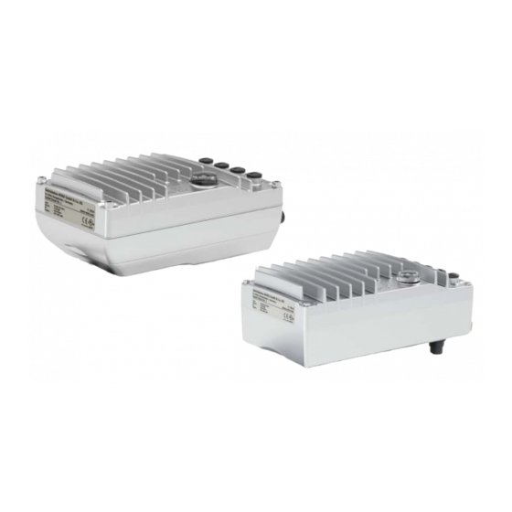
NORDAC ON / ON+ (SK 3xxP) – Manual with installation instructions 1 General The SK 300P series is based on the tried and tested NORD platform. The frequency inverters are characterised by their compact design and optimum control characteristics, and have uniform parametrisation. -
Page 9: Overview
1 General Information The device does not need to be opened at any time during its service life. All mounting, installation and commissioning works are only done on the closed device. • Assembly is done via freely accessible mounting holes. •... -
Page 10: Delivery
NORDAC ON / ON+ (SK 3xxP) – Manual with installation instructions 1.2 Delivery Examine the frequency inverter for transport damage or loose components immediately on delivery / unpacking. In case of damage, contact the carrier immediately and arrange for a careful survey. Important! This also applies if the packaging is undamaged. -
Page 11: Scope Of Delivery
1 General 1.3 Scope of delivery NOTICE Defect in the device Use of impermissible accessories and options (e.g. also options for other inverter series) may result in defects of interconnected components. • Only use accessories and options which are explicitly intended for use with this device and stated in this manual. -
Page 12: Safety, Installation And Application Information
SK 2xxE Frequency inverter of SK 200E series SK 2x0E-FDS Frequency inverter of SK 250E-FDS series SK 3xxP Frequency inverter of SK 300P series SK 5xxE Frequency inverter of SK 500E series SK 5xxP Frequency inverter of SK 500P series 1.5 Safety, installation and application information... - Page 13 1 General Unauthorised removal of covers, improper use, incorrect installation or operation causes a risk of serious personal injury or material damage. Depending on its protection class, the devices may have live, bare, moving or rotating parts or hot surfaces during operation. The device is operated with hazardous voltage.
- Page 14 NORDAC ON / ON+ (SK 3xxP) – Manual with installation instructions 2. Qualified specialist personnel Within the meaning of this basic safety information, qualified specialist personnel are persons who are familiar with the installation, assembly, commissioning and operation of the product and who have the qualifications appropriate to their work.
- Page 15 1 General The device and its optional modules contain electrostatically sensitive components, which can be easily damaged by incorrect handling. Electrical components must not be mechanically damaged or destroyed. Electrical connection Ensure that the device and the motor are specified for the correct supply voltage. Installation, maintenance and repair work must not be carried out unless the device has been disconnected from the voltage and at least 5 minutes have elapsed since the mains was switched off! (Due to charged capacitors, hazardous voltages may be present on the device for up to 5 minutes...
- Page 16 NORDAC ON / ON+ (SK 3xxP) – Manual with installation instructions Due to its operation, the device produces noises within the audible frequency range. These noises may cause long-term stress, discomfort and fatigue, with negative effects on concentration. The frequency range or the noise can be shifted to a less disturbing or almost inaudible range by adjustment of the pulse frequency.
-
Page 17: Warning And Hazard Information
1 General 1.6 Warning and hazard information Under certain circumstances, hazardous situations may occur in association with the frequency inverter. In order to give explicit warning of possibly hazardous situations, clear warning and hazard information can be found on the device and in the relevant documentation. 1.6.1 Warning and hazard information on the product The following warning and hazard information is used on the product. -
Page 18: Standards And Approvals
NORDAC ON / ON+ (SK 3xxP) – Manual with installation instructions 1.7 Standards and approvals All devices across the entire series comply with the standards and directives listed below. Applied Approval Directive Certificates Label standards Low Voltage 2014/35/EU 2014/30/EU EN 61800-5-1 EN 60529 RoHS 2011/65/EU... - Page 19 1 General Frame description Size “Suitable For Use On A Circuit Capable Of Delivering Not More Than 5000 DC Symmetrical Amperes, 410 Volts (-123 Devices) or 715 Volts (-340 Devices) Max., When Protected by R/C Semiconductor fuses, type______, manufactured by _____”, as listed in “Suitable For Use On A Circuit Capable Of Delivering Not More Than ______ rms Symmetrical Amperes, 240 (1- phase) or 480 (3-phase) Volts Max., When Protected by High-Interrupting Capacity, Current Limiting Class ____Fuses or faster, rated ______Amperes, and ____Volts”, as listed in...
-
Page 20: Type Code / Nomenclature
NORDAC ON / ON+ (SK 3xxP) – Manual with installation instructions 1.8 Type code / nomenclature 1.8.1 Name plate All of the information which is relevant for the device, including information for the identification of the device, can be obtained from the name plate. The name plate is located on the front side of the upper device shell. -
Page 21: Assembly And Installation
2 Assembly and installation 2 Assembly and installation No options can be retrofitted. All options must be recorded by NORD when ordering and before the production process. For wall mounting, the device has lugs that are freely accessible from the outside. The electrical connection of mains, motor and signal cables is only possible via respective plug connectors. -
Page 22: Dimensions Nordac On, Motor-Mounted
NORDAC ON / ON+ (SK 3xxP) – Manual with installation instructions Motor mounting on IE5+ Motor mounting on IE3 Wall mounting motor motor Type S1 mode S3 mode S1 mode S3 mode S1 mode S3 mode 85% Pn or SK 3xxP-750-340-A No derating No derating No derating... -
Page 23: Dimensions Nordac On+, Motor-Mounted
2 Assembly and installation 2.3 Dimensions NORDAC ON+, motor-mounted Housing dimensions Weight [mm] Device type Size [kg] SK 31xP-370-340-A SK 31xP-750-340-A 96.5 Depending on the motor 1.85 SK 31xP-950-340-A BU 0800 en-4521... -
Page 24: Dimensions Nordac On And Nordac On+, Wall-Mounted
NORDAC ON / ON+ (SK 3xxP) – Manual with installation instructions 2.4 Dimensions NORDAC ON and NORDAC ON+, wall-mounted Housing dimensions Weight [mm] [kg] Device type Size SK 300P-360-340-A 83.25 160.4 205.5 1.65 SK 300P-450-340-A SK 3xxP-370-340-A SK 3xxP-750-340-A 243.5 98.3 170.4 SK 3xxP-950-340-A... -
Page 25: Connections
2 Assembly and installation 2.5 Connections The device is configured according to the customer specification. Defined positions on the device apply for the selected options and features. 2.5.1 NORDAC ON motor-mounted, Size 1 Connection Function Ethernet-In Ethernet-Out DIN1 and DIN2 or DIN1 and DOUT1 DIN3 and DIN4 or DIN3 + DOUT2 Diagnostic LED and diagnostic connection RS485/RS232 Mains/24V-In (power connection, mains input) -
Page 26: Nordac On Motor-Mounted, Size 2
NORDAC ON / ON+ (SK 3xxP) – Manual with installation instructions 2.5.2 NORDAC ON motor-mounted, Size 2 Function Connection SK 300P without SK CU6-STO SK 301P with SK CU6-STO Ethernet-In Ethernet-Out DOUT1 and DOUT2 Functional safety connection DIN1 and DIN2 DIN1 and DIN2 DIN1 and DOUT1 DIN3 and DIN4... -
Page 27: Nordac On+ Motor-Mounted, Size 2
2 Assembly and installation 2.5.3 NORDAC ON+ motor-mounted, Size 2 Function Connection SK 310P without SK CU6-STO SK 311P with SK CU6-STO Ethernet-In Ethernet-Out DOUT1 and DOUT2 Functional safety connection DIN1 and DIN2 DIN1 and DIN2 DIN1 and DOUT1 DIN3 and DIN4 DIN3 and DIN4 DIN3 and DOUT2 Diagnostic LED and diagnostic connection RS485/RS232... -
Page 28: Nordac On Wall-Mounted, Size 1
NORDAC ON / ON+ (SK 3xxP) – Manual with installation instructions 2.5.4 NORDAC ON wall-mounted, Size 1 Connection Function Ethernet-In Ethernet-Out DIN1 and DIN2 DIN1 and DOUT1 DIN3 and DIN4 DIN3 and DOUT2 Diagnostic LED and diagnostic connection RS485/RS232 Not equipped Not equipped Not equipped Mains/24V-In (power connection, mains input) -
Page 29: Nordac On And Nordac On+, Wall-Mounted, Size 2
2 Assembly and installation 2.5.5 NORDAC ON and NORDAC ON+, wall-mounted, Size 2 Function Connection SK 3x0P without SK CU6-STO SK 3x1P with SK CU6-STO Ethernet-In Ethernet-Out DOUT1 and DOUT2 Functional safety connection DIN1 and DIN2 DIN1 and DIN2 DIN1 and DOUT1 DIN3 and DIN4 DIN3 and DIN4 DIN3 and DOUT2... -
Page 30: Electrical Connection
NORDAC ON / ON+ (SK 3xxP) – Manual with installation instructions 2.6 Electrical Connection WARNING Electric shock Dangerous voltages may be present at the plug contacts for the power connections (e.g. mains cable, motor cable) even when the device is not in operation. •... -
Page 31: Motor Connection
2 Assembly and installation 2.6.3 Motor connection The external motor connection is only available for wall mounting. Contact assignment Phoenix ST- 7ES1N8A6100S – 1613592 Motor connection Socket Only for Size 2 and higher BU 0800 en-4521... -
Page 32: Wiring Guidelines
NORDAC ON / ON+ (SK 3xxP) – Manual with installation instructions 2.6.4 Wiring guidelines The devices have been developed for use in an industrial environment. In this environment, electromagnetic interference can affect the device. In general, correct installation ensures safe and problem-free operation. -
Page 33: Electrical Connection Of Power Unit
2 Assembly and installation NOTICE! Damage due to high voltage The device may be damaged by electrical loads which do not correspond to its specification. • Do not perform any high voltage tests on the device itself. • Disconnect the cable which is to be tested from the device before performing a high voltage insulation test. -
Page 34: Motor Cable
NORDAC ON / ON+ (SK 3xxP) – Manual with installation instructions NOTICE Defect in the device In case of daisy chain installation, the max. permissible current flowing through the cables is limited by conductor strips. If the max. permissible current is exceeded, conductor strips in the device may be damaged. - Page 35 2 Assembly and installation The assignment of the correct brake or brake coil voltage must be taken into consideration in the design with regard to the device’s mains voltage. Information Parameter P107/P114 When connecting an electromechanical brake to the respective terminals of the device, you need to adjust the parameters P107 and P114 (“Brake reaction time”...
-
Page 36: Electrical Connection Ethernet Communication And Digital Input/Outputs
NORDAC ON / ON+ (SK 3xxP) – Manual with installation instructions 2.6.6 Electrical connection Ethernet communication and digital input/outputs Connection of the control cables is made exclusively via M12 plug connectors. The plug connectors are permanently installed at the factory. They enable the use of straight and angled (encapsulated) cable plug connectors. - Page 37 2 Assembly and installation Information Cable laying All control cables (including thermistors) must be routed separately from the mains and the motor cables to prevent interference in the device. If the cables are routed in parallel, a minimum distance of 20 cm must be maintained from cables which carry a voltage of >...
-
Page 38: Control Connection Details
NORDAC ON / ON+ (SK 3xxP) – Manual with installation instructions 2.6.6.1 Control connection details Meaning, Functions Description / Technical data Contact Parameter (designation) Meaning Function of factory setting Digital outputs Signalling of the operating statuses of the FI According to EN 61131-2 Maximum load 20 mA 24 V DC With inductive loads: Provide protection... -
Page 39: Diagnostic Connection
2 Assembly and installation 2.7 Diagnostic connection The frequency inverter is equipped with an RJ12 diagnostic interface (1). Either a PC, a Bluetooth stick or a manual control unit can be connected here via RS 232/ RS 485. Communication Device connected to different communication tools interface 24 VDC ±... -
Page 40: Encoder
NORDAC ON / ON+ (SK 3xxP) – Manual with installation instructions 2.8 Encoder The NORDAC ON+ is equipped with an RS 485 encoder interface. High-resolution encoders can transmit their information to the frequency inverter in real time via this interface. Signal +12 V DC Data +... - Page 41 2 Assembly and installation Encoder Signal Connection type Number of NORDAC ON NORDAC ON+ type poles SK 30xP SK 31xP Motor Internal mounting Universal – – RS485 RS485A Wall mounting Via X6 RS485B Motor Internal mounting Data- Universal – – SSI/BISS Data+ CLK-...
- Page 42 NORDAC ON / ON+ (SK 3xxP) – Manual with installation instructions Information Rotation direction The counting direction of the incremental encoder must correspond to the direction of rotation of the motor. If the two directions are not identical, the connections of the encoder tracks (Track A and Track B) must be switched.
-
Page 43: Display
3 Display 3 Display 3.1 LEDs The LEDs of the Ethernet connections M1 and M2 indicate the operating states of the respective slave when used for bus communication. The meaning of the display depends on the bus protocol in use. In case initiators or actuators are used, the LEDs of the digital inputs M4 and M5 indicate the corresponding signal states. -
Page 44: Display Of M1 And M2 When Using Ethernetip
NORDAC ON / ON+ (SK 3xxP) – Manual with installation instructions Labelling Display Meaning M2 – 1 ERROR = Ethernet Error EtherCAT functioning normally on the bus interface Flashing (4 Hz) General EtherCAT configuration error Single flash Bus interface has changed the EtherCAT state without authorisation Double flash EtherCAT or FI time-out (P513, P151) M2 –... -
Page 45: Display Of M1 And M2 When Using Profinet
3 Display 3.1.3 Display of M1 and M2 when using PROFINET Labelling Display Meaning M1 – 1 No connection (Link activity) Yellow flashing Connection is established, data is being transmitted Green On Connection is established, no data transmission M1 – 2 RUN = Ethernet state No error DCP signal service is triggered via the bus... -
Page 46: Display Of M4 And M5
NORDAC ON / ON+ (SK 3xxP) – Manual with installation instructions 3.1.5 Display of M4 and M5 Labelling Display Meaning M4 – 1 DIN1 Yellow On Digital input 1 = high Digital input 1 = low Red On Overload M4 – 2 DIN2 Yellow On Digital input 2 = high... -
Page 47: Commissioning
4 Commissioning 4 Commissioning WARNING Unexpected movement Connection of the supply voltage may directly or indirectly set the drive unit into motion. This can cause unexpected movement of the drive and the attached machine, which may result in serious or fatal injuries and/or material damage. -
Page 48: Selecting The Operating Mode For Motor Control
NORDAC ON / ON+ (SK 3xxP) – Manual with installation instructions 4.2 Selecting the operating mode for motor control Motors from NORD are designed as asynchronous motors in efficiency classes IE1 to IE3, and IE4 and IE5 motors are designed as synchronous motors. The NORDAC ON frequency inverter is able to control asynchronous motors with efficiency classes IE1 to IE3. - Page 49 4 Commissioning For ASM and PMSM, this operating mode provides the optimal results in control behaviour, and is especially suitable for lifting gear applications or applications with requirements on optimal dynamic behaviour (ramp times ≥ 0.05 s). This operating mode has the greatest benefit in connection with an IE4 motor (energy efficiency, dynamics, precision).
-
Page 50: Overview Of Controller Parameter Settings
NORDAC ON / ON+ (SK 3xxP) – Manual with installation instructions 4.2.2 Overview of controller parameter settings The following illustration provides an overview of all parameters which are important, depending on the selected operating mode. In principle, the following applies: The more precise the setting, the more accurate the control and the higher the possible values for the dynamics and precision of drive operation. -
Page 51: Motor Control Commissioning Steps
4 Commissioning 4.2.3 Motor control commissioning steps The main commissioning steps are mentioned below in their ideal order. Correct assignment of the inverter/motor and the mains voltage selection are assumed. Detailed information, especially for optimisation of the current, speed and position control of asynchronous motors is described in the guide "Control optimisation"... -
Page 52: Parameter
NORDAC ON / ON+ (SK 3xxP) – Manual with installation instructions 5 Parameter WARNING Unexpected movement Connection of the supply voltage may directly or indirectly set the drive unit into motion. This can cause unexpected movement of the drive and the attached machine, which may result in serious or fatal injuries and/or material damage. - Page 53 5 Parameter WARNING Unexpected movement due to overload In case of overload of the drive there is a risk that the motor will "break down" (sudden loss of torque). An overload may be caused e.g. by inadequate dimensioning of the drive unit or by the occurrence of sudden peak loads.
- Page 54 NORDAC ON / ON+ (SK 3xxP) – Manual with installation instructions Information Factory setting P523 The factory settings of the entire parameter set can be loaded at any time using parameter P523. For example, this can be useful during commissioning if it is not known which device parameters have been previously changed and could have an unexpected influence on the operating behaviour of the drive.
-
Page 55: Parameter Overview
5 Parameter 5.1 Parameter overview Operating displays P000 Operating para. disp P001 Select of disp.value P002 Display factor P003 Supervisor-Code P004 Password P005 Change password Basic parameters P100 Parameter set P101 Copy parameter set P102 Acceleration time P103 Deceleration time P104 Minimum frequency P105 Maximum frequency... - Page 56 NORDAC ON / ON+ (SK 3xxP) – Manual with installation instructions Control terminals P410 Min. freq. a-in 1/2 P411 Max. freq. a-in 1/2 P412 Nom.val process ctrl P413 PID control P comp. P414 PID control I comp. P415 PID control D comp. P416 Ramptime PI setpoint P420 Digit inputs P423...
-
Page 57: Figure 2: Explanation Of Parameter Description
5 Parameter P000 Operating para. disp. (parameter number) (parameter name) Setting range Display of typical display format (e.g. (bin = binary)) of possible setting range and number of decimal places or display range Arrays [-01] If parameters have a substructure in several arrays, this is shown here. Factory setting { 0 } Typical default setting of parameters in the as-delivered condition of the FI, or to which it is set after... -
Page 58: Operating Displays
NORDAC ON / ON+ (SK 3xxP) – Manual with installation instructions 5.1.1 Operating displays P000 Operating para. disp Display range 0.01 … 9999 Description The operating value selected in parameter P001 is displayed. Important information about the operating status of the drive can be read out as required. - Page 59 5 Parameter P003 Supervisor code Setting range 0 … 9999 Factory setting { 1 } Description The scope of the visible parameters can be influenced by setting the supervisor code. Note Display via NORDCON If parameterisation is carried out with the NORDCON software, the settings 2 ... 9999 the settings are as for the 0 setting.
-
Page 60: Basic Parameters
NORDAC ON / ON+ (SK 3xxP) – Manual with installation instructions 5.1.2 Basic parameters P100 Parameter set Setting range 0 … 3 Factory setting { 0 } Description Selection of the parameters sets to be parameterised. Four parameter sets are available. - Page 61 5 Parameter P103 Deceleration time Setting range 0.00 … 320.00 s Factory setting { 2.00 } Description The deceleration time is the time corresponding to the linear frequency reduction from the set maximum frequency P105 to 0 Hz. If an actual setpoint <100 % is being used, the deceleration time reduces accordingly.
- Page 62 NORDAC ON / ON+ (SK 3xxP) – Manual with installation instructions P106 Ramp smoothing Setting range 0 … 100 % Factory setting { 0 } Description This parameter enables smoothing of the acceleration and deceleration ramps. This is necessary for applications where gentle, but dynamic speed change is important. Ramp smoothing is carried out for every setpoint change.
- Page 63 5 Parameter P107 Brake reaction time Setting range 0 … 2.50 s Factory setting { 0.00 } Description Electromagnetic brakes have a physically-dependent delayed Brake reaction time when actuated. This can result in the dropping of the load in lifting equipment applications.
- Page 64 NORDAC ON / ON+ (SK 3xxP) – Manual with installation instructions Quad. Ramp with Delay "Quadratic ramp with delay": Combination of {2 } and {6}. Quad. comb. braking "Quadratic combined braking": Combination of {5 } and {6}. Note: This function is not suitable for PMSM motors Const.
-
Page 65: Motor Data
5 Parameter P112 Torque current limit Setting range 25 … 400 % / 401 Factory setting { 401 } Description With this parameter, a limit value for the torque-generating current can be set. This can prevent mechanical overloading of the drive. However, it cannot provide protection against mechanical blockages. - Page 66 NORDAC ON / ON+ (SK 3xxP) – Manual with installation instructions 0.09 kW 230 V 56LP/4 0.18 kW 230 V 63LP/4 0.37 kW 230 V 71LP/4 0.12 PS 230 V 56LP/4 0.24 PS 230 V 63LP/4 0.50 PS 230 V 71LP/4 0.09 kW 400 V 56LP/4 0.18 kW 400 V 63LP/4 0.37 kW 400 V 71LP/4...
- Page 67 5 Parameter P204 Nominal voltage Setting range 100 … 800 V Factory setting The default setting depends on the nominal power of the FI. Description The nominal motor voltage matches the mains voltage to the motor voltage. In combination with the nominal frequency, the voltage/frequency characteristic curve is produced.
- Page 68 NORDAC ON / ON+ (SK 3xxP) – Manual with installation instructions P210 Static boost Setting range 0 ... 400 % Factory setting { 100 } Description The static boost affects the current which generates the magnetic field. This corresponds to the no-load current of the respective motor and therefore does not depend on the load.
- Page 69 5 Parameter P214 Torque precontrol Setting range -200 ... 200 % Factory setting { 0 } Description This function allows a value for the expected torque requirement to be set in the current controller. This function can be used in lifting applications for better load take- up during starting.
- Page 70 NORDAC ON / ON+ (SK 3xxP) – Manual with installation instructions P218 Modulation depth Setting range 50 ... 110 % Factory setting { 100 } Description This setting influences the maximum possible output voltage of the FI in relation to the mains voltage.
- Page 71 5 Parameter P220 Par.-identification Setting range 0 ... 2 Factory setting { 0 } Description “Parameter identification”. For devices with output up to 7,5 kW, the motor data is determined automatically by the device via this parameter. Do not switch off the mains voltage during identification of the parameters.
- Page 72 NORDAC ON / ON+ (SK 3xxP) – Manual with installation instructions P240 EMF voltage PMSM Setting range 0 … 800 V Factory setting Depending on the FI’s nominal power Scope of application NORDAC ON+ Description The EMF voltage PMSM describes the mutual induction voltage of the motor. The value to be set can be found on the data sheet for the motor or on the name plate and is scaled to 1000 rpm.
- Page 73 5 Parameter P244 Peak current PMSM Setting range 0.1 … 1000.0 A Arrays [-01] = Peak current PMSM [-02] = Imax unsaturated Ld [-03] = Imax unsaturated Lq [-04] = Imin saturated Ld [-05] = Imin saturated Lq Factory setting Depending on the FI’s nominal power Scope of application NORDAC ON+...
- Page 74 NORDAC ON / ON+ (SK 3xxP) – Manual with installation instructions P281 Voltage mechan.brake Setting range 100 … 300 V Factory setting { 205 } Description The parameter describes the nominal voltage of the brake coil. P282 Mode mechan.brake Setting range 000 …...
-
Page 75: Speed Control
5 Parameter 5.1.4 Speed control P300 Control method Setting range 0 … 2 Factory setting { 0 } Description The control method for the motor is defined with this parameter. The following constraints must be observed: In comparison with setting {0}, setting {2} enables higher dynamics and control precision, however it requires greater effort for parameterisation. - Page 76 NORDAC ON / ON+ (SK 3xxP) – Manual with installation instructions P302 Type Univers. encoder Setting range 0 … 5 Factory setting { 1 } Description Via this parameter, the encoder type is selected. Note Setting values Value Value UART BiSS BiSS inverted SSI inverted...
- Page 77 5 Parameter P314 Torq curr ctrl limit Setting range 0 … 400 V Factory setting { 400 } Description "Torque curr. Ctrl. limit". Determines the maximum voltage increase of the torque current controller. The higher the value, the greater the maximum effect that can be exercised by the torque current controller.
- Page 78 NORDAC ON / ON+ (SK 3xxP) – Manual with installation instructions P320 Weak border Setting range 0 … 110 % Factory setting { 100 } Description The field weakening limit determines the speed /current at which the controller begins to weaken the field. At a set value of 100 % the controller begins to weaken the field at approximately the synchronous speed.
- Page 79 5 Parameter P327 Speed slip error Setting range 0 … 3000 rpm Arrays [-02] = permissible values at a standstill in [-01] = permissible deviation during order to monitor the function / wear operation (FI enabled) of a holding brake (FI ready for switch-on).
- Page 80 NORDAC ON / ON+ (SK 3xxP) – Manual with installation instructions Value from universal encoder. "Value from universal encoder": With this method the starting position of the rotor is determined from the absolute position of a universal encoder (Hiperface, EnDat with Sin/Cos track, BISS with Sin/Cos track or SSI with Sin/Cos track).
- Page 81 5 Parameter P336 Mode rotorpos ident Setting range 0 … 3 Factory setting { 0 } Description "Mode rotorpos ident" The precise position of the rotor must be known in order to operate a PMSM. This can be determined by various methods. Note Use of the parameter is only advisable if the test signal method is set (P330).
- Page 82 NORDAC ON / ON+ (SK 3xxP) – Manual with installation instructions P351 PLC set val. select. Setting range 0 … 3 Factory setting { 0 } Description Selection of the source for the control word (CTW) and the main setpoint (MSW) with active PLC functionality P350 = {1}).
-
Page 83: Control Terminals
5 Parameter 5.1.5 Control terminals P410 Min. freq. a-in 1/2 Setting range -400.0 ... 400.0 Hz Factory setting { 0.0 } Description "Minimum frequency auxiliary setpoints". The minimum frequency that can act on the setpoint via the auxiliary setpoints. Auxiliary setpoints are all frequencies that are additionally delivered for further functions in the FI: •... - Page 84 NORDAC ON / ON+ (SK 3xxP) – Manual with installation instructions P415 PID control D comp. Setting range 0 ... 400.0 % / ms Factory setting { 1.0 } Description This parameter is only effective when the function “PID current freq.” is selected. The D-component of the PID controller determines the frequency change depending on time.
- Page 85 5 Parameter Fault acknowledgem. Fault acknowledgement with an external signal. If this function 01 is not programmed, a fault can also be acknowledged by a Low Flank enable setting (P506). PTC resistor input Analogue evaluation of signal which is present. Switching level threshold approx.
- Page 86 NORDAC ON / ON+ (SK 3xxP) – Manual with installation instructions P423 Safety SS1 max. time Setting range 0.01 ... 320.00 s Factory setting { 0.1 } Description “Safety SS1 max. time” is used to delay the output monitoring of the frequency inverter if the Safety Digital Input is parameterised to Quick Stop (P424 = 2).
- Page 87 5 Parameter P426 Quick stop time Setting range 0 ... 320.00 s Factory setting { 0.10 } Description Setting of the braking time for the quick stop function which can be triggered either via a digital input, the bus control, the keyboard or automatically in case of a fault. The quick stop time is the time for the linear frequency decrease from the set maximum frequency P105 to 0 Hz.
- Page 88 NORDAC ON / ON+ (SK 3xxP) – Manual with installation instructions P429 Fixed frequency 1 Setting range -400.0 … 400.0 Hz Factory setting { 0.0 } Description Following actuation via a digital input and enabling of the device (right or left), the fixed frequency is used as a setpoint.
- Page 89 5 Parameter Torque current limit Based on motor data settings in P203 and P206. Signals high a corresponding torque load on the motor. This value can be adjusted with scaling P435. Frequency limit Based on the nominal motor frequency setting in P201. high This value can be adjusted by scaling P435.
- Page 90 NORDAC ON / ON+ (SK 3xxP) – Manual with installation instructions P435 Dig. out scaling Setting range -400 … 400% [-01] = Digital output 1 Digital output 1 (DO1) integrated into the FI [-02] = Digital output 2 Digital output 2 (DO2) integrated into the FI Factory setting All { 100 } Description...
- Page 91 5 Parameter P465 Fixed freq. Array Setting range -400.0 … 400.0 Hz Arrays [-01] = Fixed frequency array 1 [-02] = Fixed frequency array 2 … [-31] = Fixed frequency array 31 Factory setting { 0.0 } Description In the array levels, up to 31 different fixed frequencies can be set, which in turn can be encoded for the functions 50…...
- Page 92 NORDAC ON / ON+ (SK 3xxP) – Manual with installation instructions P480 Funct. BusIO In Bits Setting range 0 … 82 Arrays [-01] = BusIO In Bit 0 [-02] = BusIO In Bit 1 In Bit 0 … 3 via bus [-03] = BusIO In Bit 2 [-04] =...
- Page 93 5 Parameter P482 Norm. BusIO Out Bits Setting range -400 … 400% Arrays [-01] = BusIO Out Bit 0 [-02] = BusIO Out Bit 1 Out Bit 0 … 3 via Bus [-03] = BusIO Out Bit 2 [-04] = BusIO Out Bit 3 [-05] = BusIO Out Bit 4...
-
Page 94: Additional Parameters
NORDAC ON / ON+ (SK 3xxP) – Manual with installation instructions 5.1.6 Additional parameters P501 Inverter name Setting range A … Z (char) Arrays [-01] … [-20] Factory setting { 0 } Description Free input of a designation (name) for the device (max. 20 characters). With this, the frequency inverter can be uniquely identified for setting with NORDCON software or within a network. - Page 95 5 Parameter P505 Absolute mini. freq. Setting range 0.0 … 10.0 Hz Factory setting { 2 } Description “Absolute minimum frequency”. Specifies the frequency value that cannot be undershot by the FI. If the setpoint becomes smaller than the absolute minimum frequency, the FI switches off or changes to 0.0 Hz.
- Page 96 NORDAC ON / ON+ (SK 3xxP) – Manual with installation instructions P510 Source Setpoints Setting range 0 oder 1 oder 2 oder 8 Arrays Selection of the setpoint source. [-01] = Source main setpoint [-02] = Source 2nd setpoint Factory setting all { 0 } Description Selection of the interface, from which the frequency inverter receives its setpoints.
- Page 97 5 Parameter P516 Skip frequency 1 Setting range 0.0 … 400.0 Hz Factory setting { 0.0 } Description The output frequency around the frequency in the range between +P517 and -P517 set here is not displayed. This range is transmitted with the set deceleration and acceleration ramp; it cannot be continuously supplied to the output.
- Page 98 NORDAC ON / ON+ (SK 3xxP) – Manual with installation instructions P520 Flying start Setting range 0 … 4 Factory setting { 0 } Description This function is required to connect the FI to motors which are already rotating, e.g. for fan drives.
- Page 99 5 Parameter P523 Factory setting Setting range 0 ... 4 Factory setting { 0 } Description With the selection and activation of the relevant value, the selected parameter range is set to the factory setting. Once this setting is made, the parameter value automatically changes back to 0.
- Page 100 NORDAC ON / ON+ (SK 3xxP) – Manual with installation instructions P527 Load control freq. Setting range 0.0 ... 400.0 Hz Arrays Selection of up to 3 auxiliary values: [-01] = Auxiliary value 1 [-02] = Auxiliary value 2 [-03] = Auxiliary value 3 Factory setting All { 25.0 }...
- Page 101 5 Parameter P535 t Motor Setting range 0 … 24 Factory setting { 0 } Description The motor temperature is calculated depending on the output current, the time and the output frequency (cooling). If the temperature limit value is reached then switch off occurs with error message E2.1.
- Page 102 NORDAC ON / ON+ (SK 3xxP) – Manual with installation instructions P537 Pulse Disconnection Setting range 10 ... 200 % / 201 Factory setting { 150 } Description This function prevents rapid shutdown of the FI according to the load. With the pulse switch-off enabled, the output current is limited to the set value.
- Page 103 5 Parameter P540 Direction of rotation mode Setting range 0 ... 7 Factory setting { 0 } Description For safety reasons this parameter can be used to prevent a rotation direction reversal and therefore prevent an incorrect rotation direction. Note This function does not operate with active position control.
- Page 104 NORDAC ON / ON+ (SK 3xxP) – Manual with installation instructions P543 Bus actual value Setting range 0 … 57 Arrays [-01] = Actual bus value 1 [-02] = Actual bus value 2 [-03] = Actual bus value 3 [-04] = Actual bus value 4 [-05] = Actual bus value 5...
- Page 105 5 Parameter P551 Drive profile Setting range 0 … 3 Factory setting { 0 } Description Activation of a process data profile. Setting values Value Meaning No specific drive profile. CANopen DS402 CANopen drive profile according to DS402. Reserve Nord-Custom Drive profile with freely assignable bits.
- Page 106 NORDAC ON / ON+ (SK 3xxP) – Manual with installation instructions P555 P-limit chopper Setting range 5 … 100 % Factory setting { 100 } Description "Chopper power limit“. With this parameter it is possible to program a manual (peak) power limit for the braking resistor.
- Page 107 5 Parameter P559 DC run-on time Setting range 0.00 ... 30.00 sec Factory setting { 0.50 } Description After a stop signal and elapse of the brake ramp, direct current is applied to the motor for a short time. This should completely stop the drive. Depending on the inertia, the time for which the current is applied can be set in this parameter.
-
Page 108: Information
NORDAC ON / ON+ (SK 3xxP) – Manual with installation instructions 5.1.7 Information P700 Actual operating status Display range 0.0 … 99.9 Arrays [-01] = Actual error Indicates the presently active (unacknowledged) fault. [-02] = Actual warning Indicates a present warning message. [-03] = Reason for switch-on Indicates the reason for active switch-on inhibit. - Page 109 5 Parameter P706 P set last error Display range 0 ... 3 Arrays [-01] … [-10] Description “Parameter set last error 1 … 10”. This parameter stores the parameter set code that was active when the error occurred. Data for the previous 10 faults are stored. P707 Software-Version Display range...
- Page 110 NORDAC ON / ON+ (SK 3xxP) – Manual with installation instructions P712 Energy consumption Display range 0.00 ... 19 999 999.99 kWh Description Displays the energy consumption (cumulative energy consumption over the life of the FI). P713 Braking resistor energy Display range 0.00 ...
- Page 111 5 Parameter P722 Actual voltage Display range 0 ... 500 V Description Displays the actual AC voltage supplied by the FI output. P723 Voltage -d Display range -500 ... 500 V Description "Actual voltage component Ud". Displays the actual field voltage component. P724 Voltage -q Display range...
- Page 112 NORDAC ON / ON+ (SK 3xxP) – Manual with installation instructions P733 Phase V current Display range 0.0... 500.0 A Description Displays the actual V phase current. Note This value can deviate from the value in P719 due to the measurement procedure used, even with symmetrical output currents.
- Page 113 5 Parameter P740 PZD bus in Display range 0000 … FFFF (hex) Arrays [-01] = Control word Control word [-02] = Set value1 Set value data from main set value P509 … [-06] = Setvalue 5 The displayed value depicts all Bus In Bit [-07] = Res.
- Page 114 NORDAC ON / ON+ (SK 3xxP) – Manual with installation instructions P741 PZD bus out Display range 0000 … FFFF (hex) Arrays [-01] = Status word bus Status word corresponding to selection in P551 [-02] = Bus actual value 1 …...
- Page 115 5 Parameter Array [-03] Additional interfaces Bit 0 Interface for IOE present Bit 1 TTL encoder interface Bit 2 HTL encoder functionality Bit 3 Diagnostic interface Bit 4 External 24 V supply Bit 5 CU6 interface present Array [-04] Functionalities Bit 0 POSICON functionality (PLC) Bit 1...
- Page 116 NORDAC ON / ON+ (SK 3xxP) – Manual with installation instructions P751 Counter statistics Display range 0 ... 9999 Arrays [-01] … [-25] Description Display of the frequency with which the errors according to P750 have occurred. Note The arrays of parameters P750 and P751 are directly related. Example: In P751 [-01], the number of error messages according to P750 [-01] are displayed.
-
Page 117: Operating Status Messages
6 Operating status messages 6 Operating status messages In case of deviations from the normal operating status, a message is output. There are: • Error messages: Faults cause the device to switch off. • Warning messages: A limit value has been reached. The device will continue to run. If the cause for the warning persists, the device enters the fault state. -
Page 118: Messages
NORDAC ON / ON+ (SK 3xxP) – Manual with installation instructions 6.2 Messages In the following tables you will find a list of possible errors, a description of the cause and instructions for troubleshooting. Under “Further notes” you will find solution approaches related to parameterisation. - Page 119 6 Operating status messages Overcurrent I²t lim. E003 The current limit (I t) has been exceeded (e.g more than 1.5x the rated current for 60 s). • Reduce motor load • Check system for blockage or overload • Check rotary encoder settings (resolution, defect, connection) Further notes: •...
- Page 120 NORDAC ON / ON+ (SK 3xxP) – Manual with installation instructions Overcurrent measurem. E004 Pulse switch-off (P537) has been reached three times within 50 ms. • Reduce motor load • Check system for blockage or overload Further notes: • Error message is only possible if (P112) and (P536) are switched off •...
- Page 121 6 Operating status messages E008 Parameter loss Error in EEPROM data (maximum EEPROM value • Software version of the stored data set not compatible exceeded) with the software version of the FI Note: Faulty parameters are automatically reloaded (factory setting). EMC interferences (see also E020) •...
- Page 122 NORDAC ON / ON+ (SK 3xxP) – Manual with installation instructions E012 12.1 Limit moto./Customer The drive switch-off limit has triggered. • Reduce motor load • Check system for blockage or overload Further notes: Check settings P534 [-01] • E012 12.2 Limit gen.
- Page 123 6 Operating status messages E013 13.2 Disconnect. control The slip error switch-off monitoring has triggered. The motor could not follow the setpoint. • Check system for blockage or overload Further notes: • Check motor data (P201 … P209) • Check motor circuit •...
- Page 124 NORDAC ON / ON+ (SK 3xxP) – Manual with installation instructions E016 16.2 Change phase direct. The motor phase sequence (U – V – W) has been changed during operation (enable). Further notes: • Check parameter values in (P583) • Has parameter set (P100) been switched over? E016 16.5...
- Page 125 6 Operating status messages E022 22.5 PLC unknown comm. A command code in the program cannot be executed because it is not known. • Program error, behaviour as for Error 22.1 • Version of the PLC and the NORDCON version do not match E022 22.6...
- Page 126 NORDAC ON / ON+ (SK 3xxP) – Manual with installation instructions Warnings Coding Cause ERROR TEXT • Remedy Group Number Inverter overtemp. C001 Temperature monitoring of the inverter Temperature range has been exceeded or undershot. • Reduce or increase ambient temperature •...
- Page 127 6 Operating status messages C003 Torque limit The limit value of the torque generating current (parameterised, mechanical load limit) has been reached. • Check system for blockage or overload Further notes: Check value in P112. • C003 Current limit The limit value of the FI output current (parameterised FI load limit) has been reached.
- Page 128 NORDAC ON / ON+ (SK 3xxP) – Manual with installation instructions C012 12.1 Limit moto./Customer The motor switch-off limit is reached. • Reduce motor load • Check system for blockage or overload Further notes: Check settings P534 [-01] • C012 12.2 Limit gen.
- Page 129 6 Operating status messages Switch-on blocks Coding Cause ERROR TEXT • Remedy Group Number Volt. blocked by IO The input which is parameterised with the “Voltage disable” function (P420/P480) is not set (“Low”). • Set input (“High”) • Check connections and cables on both sides Further notes: Check parameterisation of digital functions (P420/ P480) •...
-
Page 130: Faq Operational Problems
NORDAC ON / ON+ (SK 3xxP) – Manual with installation instructions 6.3 FAQ operational problems Fault Possible cause Remedy • Check connections and supply Device will not start • No mains voltage or wrong mains cables (all LEDs off) voltage •... -
Page 131: Technical Data
7 Technical data 7 Technical data 7.1 General frequency inverter data Function Specification Output frequency 0.0 … 400.0 Hz Pulse frequency 3.0 … 16.0 kHz, factory setting = 6 kHz Power reduction > 6 kHz for 400 V devices Typical overload capacity 150% for 60 s, 200% for 3.5 s Frequency inverter efficiency >... -
Page 132: Technical Data For Determining The Energy Efficiency Level
NORDAC ON / ON+ (SK 3xxP) – Manual with installation instructions 7.2 Technical data for determining the energy efficiency level The following tables relate to the provisions of the Ecodesign EU Regulation 2019/1781. Rel. losses (rel. motor stator frequency / rel. torque-producing current) 90/100 90/50 50/100... -
Page 133: Electrical Data 3~400 V
7 Technical data 7.2.1 Electrical data 3~400 V 7.2.1.1 NORDAC ON, Size 1 Device type SK 300P–360 SK 300P–450 With STO – – 400 V 0.37 kW 0.45 kW Nominal power 480 V 0.5 hp 0.6 hp 400 V 3 AC 400 V -20% … 480 V +10%, 47 … 63 Hz Mains voltage 1.5 A 1.7 A... -
Page 134: Additional Information
NORDAC ON / ON+ (SK 3xxP) – Manual with installation instructions 8 Additional information 8.1 Electromagnetic compatibility (EMC) 8.1.1 General Provisions As of July 2007, all electrical equipment which has an intrinsic, independent function and which is sold as an individual unit for end users, must comply with Directive 2004/108/EEC (formerly Directive EEC/89/336). -
Page 135: Emc Evaluation
8 Additional information 8.1.2 EMC evaluation Two standards must be observed when evaluating electromagnetic compatibility. 1. EN 55011 (environmental standard) In this standard, the limit values are defined in dependence on the basic environment in which the product is operated. A distinction is made between two environments, where the first environment describes the non-industrial living and business area without its own high-voltage or medium- voltage distribution transformers. -
Page 136: Emc Of Device
NORDAC ON / ON+ (SK 3xxP) – Manual with installation instructions 8.1.3 EMC of device NOTICE EMC interference to the environment This device produces high-frequency interference, which may make additional suppression measures necessary in domestic environments ( � 8.1 "Electromagnetic compatibility (EMC)"). �... -
Page 137: Table 5: Overview According To Product Standard En 61800-3
8 Additional information EMC overview of standards that are used in accordance with EN 61800-3 as checking and measuring procedures: Interference emission Cable-related emission EN 55011 (interference voltage) Radiated emission EN 55011 (interference field strength) C3 (size 2) Interference immunity EN 61000-6-1, EN 61000-6-2 ESD, discharge of static electricity EN 61000-4-2... -
Page 138: Eu Declaration Of Conformity
NORDAC ON / ON+ (SK 3xxP) – Manual with installation instructions 8.1.4 EU Declaration of Conformity BU 0800 en-4521... -
Page 139: Reduced Output Power
8 Additional information 8.2 Reduced output power The frequency inverters are designed for special overload situations. For example, 1.5x overcurrent can be used for 60 s. For approx. 3.5 s, 2x overcurrent is possible. A reduction of the overload capacity or its duration must be considered for the following circumstances: •... -
Page 140: Reduced Overcurrent Due To Time
NORDAC ON / ON+ (SK 3xxP) – Manual with installation instructions 8.2.2 Reduced overcurrent due to time The possible overload capacity changes depending on the duration of an overload. Several values are cited in this table. If one of these limiting values is reached, the frequency inverter must have sufficient time (with low utilisation or without load) in order to regenerate itself. -
Page 141: Reduced Overcurrent Due To Output Frequency
8 Additional information 8.2.3 Reduced overcurrent due to output frequency To protect the power unit at low output frequencies (<4.5Hz) a monitoring system is provided, with which the temperature of the IGBTs (insulated-gate bipolar transistor) due to high current is determined. -
Page 142: Reduced Output Current Due To Low Voltage
NORDAC ON / ON+ (SK 3xxP) – Manual with installation instructions 8.2.4 Reduced output current due to low voltage The frequency inverters are thermally designed with regard to the rated output currents. For lower low voltages larger currents cannot be used in order to keep the output power constant. For mains voltages above 400 V the permissible output current is reduced inversely proportional to the mains voltage in order to compensate for switching losses. -
Page 143: Options For Optimising The Energy Efficiency
8 Additional information 8.4 Options for optimising the energy efficiency WARNING Unexpected movement due to overload In case of overload of the drive there is a risk that the motor will "break down" (sudden loss of torque). An overload may be caused e.g. by inadequate dimensioning of the drive unit or by the occurrence of sudden peak loads. -
Page 144: Scaling Of Set Point/Actual Values
NORDAC ON / ON+ (SK 3xxP) – Manual with installation instructions 8.5 Scaling of set point/actual values The following table contains details for the standardisation of typical setpoint and actual values. These details relate to parameters (P543), (P546), (P740) or (P741). Designation Bus signal Setpoints... -
Page 145: Definition Of Set And Actual Value Processing (Frequencies)
8 Additional information 8.6 Definition of set and actual value processing (frequencies) The frequencies used in parameter P543 are processed in various ways according to the following table. Control and motor Setpoint source and Signal processing model (slip setpoint selection and ramp determination) Output to ... -
Page 146: Connection Accessories
NORDAC ON / ON+ (SK 3xxP) – Manual with installation instructions 8.7 Connection accessories The material for establishing the electrical connection is not included in the scope of delivery of the frequency inverter. However, it can be obtained from NORD. 8.7.1 Motor cable Pre-assembled cables for the motor connection are available (www.nord.com). -
Page 147: Maintenance And Servicing Information
9 Maintenance and servicing information 9 Maintenance and servicing information 9.1 Maintenance information NORD frequency inverters are maintenance-free � 7.1 "General frequency inverter data"in normal � � � � � operation. Dusty environments If the device is operated in dusty air, the cooling surfaces must be cleaned with compressed air at regular intervals. -
Page 148: Replace Upper Part Of The Device
NORDAC ON / ON+ (SK 3xxP) – Manual with installation instructions 9.1.1 Replace upper part of the device After the warranty period has expired, in case of a failure that cannot be remedied, you may return only the upper part of the device to NORD Electronic DRIVESYSTEMS GmbH for repair. For the replacement of the upper part, all cable connections from the base part to the upper part must be disconnected. -
Page 149: Dismantle Upper Part Of The Device
9 Maintenance and servicing information 9.1.1.1 Dismantle upper part of the device Requirement Ensure free access to the upper part of the device – particularly with motor-mounted devices. If required, dismantle the motor with attached frequency inverter to gain access to the device. Procedure 1. -
Page 150: Replacement Material
NORDAC ON / ON+ (SK 3xxP) – Manual with installation instructions 9.1.1.3 Replacement material Designation SK TIE6-… …1-CNK-BSC …2-CNK-BSC …1-CNK-ADV …2-CNK-ADV …-SCREW-STD Part number 275188200 275188205 275188201 275188206 275188209 Edge connector for motor connection Edge connector for mains connection Edge connector for 24 V supply Edge connector Temperature sensor... -
Page 151: Service Notes
9 Maintenance and servicing information 9.2 Service notes Our Technical Support is available in case of technical queries. If you contact our technical support, please have the precise device type (type plate/display), accessories and/or options, the software version used (P707) and the series number (type plate) at hand. -
Page 152: Abbreviations
NORDAC ON / ON+ (SK 3xxP) – Manual with installation instructions 9.3 Abbreviations Asynchronous machine, asynchronous Ground, common reference potential motor AOUT Analogue output In / Out (Input / Output) Current Flux Control (current-controlled, Field current (current vector control) field-oriented control) DI (DIN) Digital input Light-emitting Diode... - Page 153 Key word index Key word index Absolute min. freq. (P505) ......95 CE mark ............134 Acceleration time (P102) ....... 60 Change password (P005) ......59 Accessories ..........146 Characteristics of the NORDAC ON ....9 Daisy chain cable ........146 Characteristics of the NORDAC ON+ .....
- Page 154 NORDAC ON / ON+ (SK 3xxP) – Manual with installation instructions Digital out function (P434) ......88 Fixed frequency 5 (P433) ......88 Display ............43 Fixed frequency array (P465) ....... 91 Drive profile (P551) ........105 Fixed frequency mode (P464) ...... 90 Dynamic boost (P211) ........
- Page 155 Key word index Load monitoring minimum (P526) ....99 Overvoltage ..........120 Mains cable ..........146 P - torque limit factor (P111) ......64 Mains connection ........... 25 P set last error (P706) ......... 109 Power connection ........30 Par.-identification (P220) ......71 Maintenance ..........
- Page 156 NORDAC ON / ON+ (SK 3xxP) – Manual with installation instructions Quick stop time (P426) ........87 Spring-loaded brake Nominal voltage (P281)74 Spring-loaded brake Operating mode (P282)74 State of digital in. (P708) ......109 Ramp smoothing P106 ........62 State of digital out (P711) ......109 Ramptime PI setpoint (P416) ......
- Page 157 Key word index Voltage –q (P724) ........111 Watchdog ............90 Watchdog time (P460) ........90 Wiring guidelines ........... 32 Warnings............117 BU 0800 en-4521...
- Page 158 NORDAC ON / ON+ (SK 3xxP) – Manual with installation instructions BU 0800 en-4521...
- Page 159 Key word index BU 0800 en-4521...
Need help?
Do you have a question about the SK 300P Series and is the answer not in the manual?
Questions and answers