Sign In
Upload
Manuals
Brands
Nord Drivesystems Manuals
Inverter
SK 550P
Nord Drivesystems SK 550P Manuals
Manuals and User Guides for Nord Drivesystems SK 550P. We have
3
Nord Drivesystems SK 550P manuals available for free PDF download: Manual With Installation Instructions, User Manual, Supplementary Manual
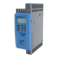
Nord Drivesystems SK 550P Manual With Installation Instructions (256 pages)
Frequency inverters
Brand:
Nord Drivesystems
| Category:
Inverter
| Size: 5.04 MB
Table of Contents
Table 1: Version List
3
Table of Contents
5
1 General
9
Device Characteristics
10
Table 2: Overview of FI Characteristics
12
Delivery
13
Scope of Delivery
13
Safety, Installation and Application Information
17
Explanation of Markings
21
Warning Information on the Product
22
Table 3: Warning Symbols on the Product
22
Standards and Approvals
23
UL and CSA Approval
23
Table 4: Standards and Approvals
23
Type Code / Nomenclature
25
Rating Plate
25
2 Assembly and Installation
27
Figure 1: Installation Spacings
27
Frequency Inverter Installation
28
EMC Kit
29
Braking Resistor (BR)
32
Figure 2: Frequency Inverter with Bottom-Mounted Braking Resistor SK BRU5
32
Electrical Data for Braking Resistors
33
Table 5: Technical Data Bottom Mounted Braking Resistor SK BRU5
33
Table 6: Technical Data Chassis Braking Resistor SK BR2
33
Table 7: Technical Details of the Braking Resistor Temperature Switch
33
Monitoring of the Braking Resistor
34
Monitoring with a Temperature Switch
34
Monitoring with Current Measurement and Calculation
34
Chokes
35
Mains Chokes
35
Mains Choke SK CI5
35
Motor Choke SK CO5
37
Electrical Connection
38
Overview of Connections
39
Wiring Guidelines
41
Electrical Connection of Power Unit
42
Table 8: Tools
42
Table 9: Connection Data
42
Electromechanical Brake
43
Mains Connection (PE, L1, L2/N, L3)
43
Motor Cable
44
Braking Resistor (B+, B-)
45
DC Coupling (B+, DC-)
45
Figure 3: Illustration of a DC-Coupling
46
Figure 4: Diagram of a DC Coupling with an Input/Feedback Unit
47
Electrical Connection of the Control Unit
48
Incremental Encoder
56
Table 10: Colour and Contact Assignments for NORD TTL / HTL Incremental Encoders
57
Fans
58
Removing the Fan
58
Installing the Fan
58
3 Options
59
Overview of Option Modules
59
Controlbox SK TU5-CTR
61
Control Keys
61
Display
62
Displays
62
Operation
62
Status Displays
63
Control
63
Parameterisation
64
Figure 5: Controlbox Menu Structure
65
Frequency Addition and Subtraction Via Control Boxes
66
Connection of Multiple Devices to One Parametrisation Tool
66
4 Commissioning
67
Factory Settings
67
Figure 6: Motor Type Plate
68
Selecting the Operating Mode for Motor Control
69
Explanation of the Operating Modes (P300)
69
Overview of Controller Parameter Settings
71
Motor Control Commissioning Steps
72
Minimum Configuration of Control Connections
73
Temperature Sensors
74
5 Parameter
76
Figure 7: Explanation of Parameter Description
79
Parameter Overview
80
Operating Display
83
DS402 Parameter
85
Basic Parameter
98
Motor Data / Characteristic Curve Parameters
106
Control Parameters
117
Control Terminals
127
Additional Parameters
156
Positioning
183
Information
184
6 Operating Status Messages
201
Display of Messages
202
Messages
205
7 Technical Data
217
General Data
217
Technical Data for Determining the Energy Efficiency Level
218
Electrical Data
219
Electrical Data 230 V
219
Electrical Data 400 V
221
8 Additional Information
224
Setpoint Processing
224
Figure 8: Setpoint Processing
225
Process Controller
226
Figure 9: Process Controller Flow Diagram
226
Process Controller Application Example
227
Process Controller Parameter Settings
228
Electromagnetic Compatibility (EMC)
229
General Provisions
229
EMC Evaluation
229
EMC of Device
230
Table 11: EMC Comparison between en 61800-3 and en 55011
230
Table 12: EMC, Max. Shielded Motor Cable Length with Regard to Compliance with the Limit Value Classes
231
Table 13: Overview According to Product Standard en 61800-3
231
Figure 10: Wiring Recommendation
232
EU Declaration of Conformity
233
Reduced Output Power
234
Increased Heat Dissipation Due to Pulse Frequency
234
Figure 11: Heat Losses Due to Pulse Frequency
234
Reduced Overcurrent Due to Time
235
Table 14: Overcurrent Relative to Time
235
Reduced Overcurrent Due to Output Frequency
236
Table 15: Overcurrent Relative to Pulse and Output Frequency
236
Reduced Output Current Due to Low Voltage
237
Reduced Output Current Due to the Heat Sink Temperature
237
Operation on the FI Circuit Breaker
237
Figure 12: Reduced Output Current Due to Low Voltage
237
NORD System Bus
238
Description
238
Figure 13: Example of the Structure of a NORD System Bus
239
NORD System Bus Participants
240
Physical Structure
240
Options for Optimising the Energy Efficiency
241
Figure 14: Energy Efficiency Due to Automatic Flux Optimisation
241
Scaling of Set Point/Actual Values
242
Table 16: Scaling of Set/Actual Values (Selection)
242
Definition of Setpoint and Actual Value Processing (Frequencies)
243
Table 17: Processing of Setpoints and Actual Values in the Frequency Inverter
243
9 Maintenance and Servicing Information
244
Maintenance Instructions
244
Service Notes
245
Abbreviations
246
Advertisement
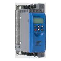
Nord Drivesystems SK 550P User Manual (220 pages)
Brand:
Nord Drivesystems
| Category:
DC Drives
| Size: 4.35 MB
Table of Contents
Table 1: Version List
2
Table of Contents
4
1 General
8
Device Characteristics
9
Table 2: Overview of FI Characteristics
11
Delivery
12
Scope of Delivery
12
Safety, Installation and Operating Instructions
16
Explanation of Markings
20
Warning Information on the Product
21
Table 3: Warning Information on the Product
21
Standards and Approvals
22
UL and CSA Approval
22
Table 4: Standards and Approvals
22
Type Code / Nomenclature
23
Type Plate
23
2 Assembly and Installation
25
Figure 1: Installation Spacings
25
Frequency Inverter Installation
26
Braking Resistor (BR)
27
Figure 2: Frequency Inverter with Bottom-Mounted Braking Resistor SK BRU5
27
Electrical Data for Braking Resistors
28
Table 5: Technical Data Bottom Mounted Braking Resistor SK BRU5
28
Table 6: Technical Data Chassis Braking Resistor SK BR2
28
Table 7: Technical Data, Temperature Switch for Chassis Braking Resistor SK BR2
28
Dimensions of Bottom-Mounted Braking Resistor SK BRU5
29
Dimensions of Chassis BR SK BR2
29
Figure 3: Illustration of Mounting the BRU5 on the Frequency Inverter
29
Table 8: Dimensions of Bottom-Mounted Braking Resistor SK BRU5
29
Table 9: Dimensions of Chassis Brake Resistor SK BR2
29
Monitoring of the Braking Resistor
30
Monitoring with a Temperature Switch
30
Monitoring with Current Measurement and Calculation
30
Chokes
31
Input Choke SK CI1
31
Table 10: Input Choke Data for SK CI1
32
Output Choke SK CO1
33
Table 11: Output Choke Data for SK CO1
33
Line Filter
34
Mains Filter SK HLD
34
Table 12: Output Choke Data for SK CO1
34
Table 13: Mains Filter HLD
34
Electrical Connection
35
Overview of Connections
36
Wiring Guidelines
38
Electrical Connection of Power Unit
39
Table 14: Tools
39
Table 15: Connection Data
39
Electromechanical Brake
40
Mains Connection (PE, L1, L2/N, L3)
40
Motor Cable (U, V, W, PE)
41
Braking Resistor (B+, B-)
42
DC Coupling (B+, DC-)
42
Figure 4: Illustration of a DC-Coupling
43
Figure 5: Diagram of a DC Coupling with an Input/Feedback Unit
44
Electrical Connection of the Control Unit
45
Colour and Contact Assignments for Encoders
51
Table 16: Colour and Contact Assignments for NORD TTL / HTL Incremental Encoders
52
RJ45 WAGO Connection Module
53
Table 17: RJ45 WAGO Connection Module
53
3 Options
54
Overview of Option Modules
54
Table 18: Overview of Technology Units, Controlbox
54
Table 19: Overview of Technology Units, Interfaces
54
Table 20: Overview of Technology Units and Other Option Modules
54
Tu5-Ctr
56
Control Keys
56
Display
57
Displays
57
Operation
57
Status Displays
58
Control
58
Parameterisation
59
Figure 6: Controlbox Menu Structure
60
Frequency Addition and Subtraction Via Control Boxes
61
Connection of Multiple Devices to One Parametrisation Tool
61
4 Commissioning
62
Factory Settings
62
Figure 7: Motor Type Plate
63
Selecting the Operating Mode for Motor Control
64
Explanation of the Operating Modes (P300)
64
Overview of Control Parameter Settings
66
Motor Control Commissioning Steps
67
Minimum Configuration of Control Connections
68
Temperature Sensors
69
Table 21: Temperature Sensors, Adjustment
69
5 Parameter
71
Figure 8: Explanation of Parameter Description
74
Parameter Overview
75
Operating Display
78
Basic Parameter
80
Motor Data / Characteristic Curve Parameters
88
Control Parameters
98
Control Terminals
108
Additional Parameters
137
Positioning
162
Information
163
6 Operating Status Messages
178
Display of Messages
179
Figure 9: Leds - Status Displays on the Device
179
Messages
181
7 Technical Data
191
General Data
191
Electrical Data
192
Electrical Data 230 V
192
Electrical Data 400 V
194
8 Additional Information
196
Setpoint Processing
196
Figure 10: Setpoint Processing
197
Process Controller
198
Figure 11: Process Controller Flow Diagram
198
Process Controller Application Example
199
Process Controller Parameter Settings
200
Electromagnetic Compatibility (EMC)
201
General Provisions
201
EMC Evaluation
201
EMC of Device
202
Table 22: EMC Comparison between en 61800-3 and en 55011
202
Figure 12: Wiring Recommendation
203
Table 23: EMC, Max. Shielded Motor Cable Length with Regard to Compliance with the Limit Value Classes
203
Table 24: Overview According to Product Standard en 61800-3
203
EU Declaration of Conformity
204
Reduced Output Power
205
Increased Heat Dissipation Due to Pulse Frequency
205
Figure 13: Heat Losses Due to Pulse Frequency
205
Reduced Overcurrent Due to Time
206
Table 25: Overcurrent Relative to Time
206
Reduced Overcurrent Due to Output Frequency
207
Table 26: Overcurrent Relative to Pulse and Output Frequency
207
Reduced Output Current Due to Mains Voltage
208
Reduced Output Current Due to the Heat Sink Temperature
208
Operation on the FI Circuit Breaker
208
Figure 14: Output Current Due to Mains Voltage
208
Energy Efficiency
209
Figure 15: Energy Efficiency Due to Automatic Flux Optimisation
209
Standardisation of Setpoint / Target Values
210
Table 27: Scaling of Setpoints and Actual Values (Selection)
210
Definition of Setpoint and Actual Value Processing (Frequencies)
211
Table 28: Processing of Setpoints and Actual Values in the Frequency Inverter
211
9 Maintenance and Servicing Information
212
Maintenance Instructions
212
Service Notes
213
Abbreviations
214
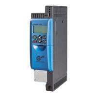
Nord Drivesystems SK 550P Supplementary Manual (64 pages)
Brand:
Nord Drivesystems
| Category:
Inverter
| Size: 1.27 MB
Table of Contents
Table of Contents
4
1 Introduction
6
General
6
Documentation
6
Document History
6
About this Manual
7
Other Applicable Documents
7
Presentation Conventions
7
Warning Information
7
Other Information
7
Safety, Installation and Application Information
7
2 Function Description
11
Design of the Safe Shut-Down Method
11
Safe Shut-Down Methods
12
Safe Pulse Block
12
Safety Digital Input
13
Safety Functions
14
Safe Torque Off, STO
14
Safe Stop 1 with Time Control, SS1-T
15
Priorities and Response to Faults
15
Examples / Implementation
15
STO Function
15
SS1-T Function
19
Simple Re-Start Block
21
Example Without Safe Pulse Block
22
Exclusion of Wiring Faults
25
3 Assembly and Installation
28
Installation and Assembly
28
Assembly of an SK CU5-STO and SK CU5-MLT Customer Unit
28
Electrical Connection
29
Wiring Guidelines
29
Mains Connection
29
Control Cable Connections
31
Control Terminal Details
31
Details of the Safe Shut-Down Method
32
Wiring and Shielding
32
Operation with OSSD
32
Individual Operation
33
Multiple Device Operation
34
Emc
35
4 Commissioning
36
Commissioning Steps for STO
36
SS1-T Commissioning Steps
37
Validation
40
5 Parameters
41
Parameterisation
41
Description of Parameters
42
Control Terminals
43
Additional Parameters
47
6 Operating Status Messages
48
7 Additional Information
51
Protective Switching Devices
51
Output Voltage of Safety Devices
51
Switching Capacity and Current Load
51
OSSD Outputs, Test Pulses
53
Safety Categories
54
Iec 60204-1:2016
54
Iec 61800-5-2:2016
54
Iec 61508:2010
54
Iso 13849-1:2015
55
8 Technical Data
56
Safe Pulse Block and Safety Digital Input
56
9 Appendix
58
Maintenance Information
58
Repair Information
58
Service and Commissioning Information
59
Documents and Software
59
Certificates
59
Abbreviations
60
Advertisement
Advertisement
Related Products
Nord Drivesystems SK 500P Series
Nord Drivesystems SK 510P
Nord Drivesystems SK 540P
Nord Drivesystems SK 530P
Nord Drivesystems NORDAC FLEX SK 205E Series
Nord Drivesystems NORDAC FLEX SK 225E Series
Nord Drivesystems NORDAC FLEX SK 235E Series
Nord Drivesystems SK 250E
Nord Drivesystems SK280E-FDS
Nord Drivesystems NORDAC FLEX SK 230E Series
Nord Drivesystems Categories
DC Drives
Inverter
Engine
Industrial Equipment
Controller
More Nord Drivesystems Manuals
Login
Sign In
OR
Sign in with Facebook
Sign in with Google
Upload manual
Upload from disk
Upload from URL