Table of Contents
Advertisement
Quick Links
Advertisement
Table of Contents

Related Manuals for MEDAP WISTA SP 1070


Summary of Contents for MEDAP WISTA SP 1070
- Page 1 OPERATING INSTRUCTIONS SURGICAL ASPIRATOR MEDAP-TWISTA SP 1070 GA 5752 1555 DE 28...
- Page 2 Subject to technical modification! Illustrations and technical specifications may vary slightly from those in these Operating Instructions as a result of ongoing product development. V28 2021-02 GA 5752 1555 DE 28...
-
Page 3: Table Of Contents
Table of contents Table of contents Introduction .............................. 6 Foreword ..............................6 How to use these operating instructions ....................6 1.2.1 Abbreviations ..........................6 1.2.2 Symbols ............................6 1.2.2.1 Cross-references ....................... 6 1.2.2.2 Actions and responses ....................6 1.2.3 Definitions ............................ 7 1.2.3.1 Design of safety notes .................... - Page 4 Table of contents Scope of delivery ............................19 Mounting the stand ........................... 20 Mounting the tube holder.......................... 23 Mounting the foot switch ........................... 23 Overflow protection device/tube connector ....................23 3.6.1 Mounting the mechanical overflow protection device (REF 5752 1775) ........24 3.6.1.1 Inserting the overflow protection device ..............
- Page 5 Table of contents 6.2.2 Suitable disinfectants ......................... 43 6.2.3 Disinfection procedure ....................... 43 6.2.4 Disinfection procedures ......................43 Maintenance ............................45 General ..............................45 Period tests .............................. 45 Visual and functional inspections ......................45 Malfunctions and troubleshooting......................46 Replace mains fuse ..........................47 Repairs ..............................
-
Page 6: Introduction
Introduction Foreword Introduction Foreword Your facility has selected the leading-edge medical technology made by ATMOS. We sincerely appreciate the trust you have placed in us. How to use these operating instructions These operating instructions are provided to familiarise you with the features of this ATMOS product. -
Page 7: Definitions
Introduction How to use these operating instructions 1.2.3 Definitions 1.2.3.1 Design of safety notes Pictogram Descriptor Text The text for the safety note DANGER! describes the type of risk and Indicates a direct and immediate risk to how to avert it. persons which may be fatal or result in most serious injury. - Page 8 Introduction How to use these operating instructions Symbols Identification Labelling in compliance with the ISO 15223-1 standard. Symbol for ‘Product number’. Symbol for ‘Follow Operating Instructions’. Labelling in compliance with the ISO 15223-1 standard. Symbol for ‘Name and address of the manufacturer as well as date of manufacture’.
-
Page 9: Disposal
Introduction How to use these operating instructions Symbols Identification Packaging label. Symbol for ‘Top’. Labelling in compliance with the ISO 15223-1 standard. Symbol for ‘Temperature limitations’. Labelling in compliance with the ISO 15223-1 standard. Symbol for ‘Relative humidity’. Labelling in compliance with the ISO 15223-1 standard. Symbol for ‘Atmospheric pressure’. -
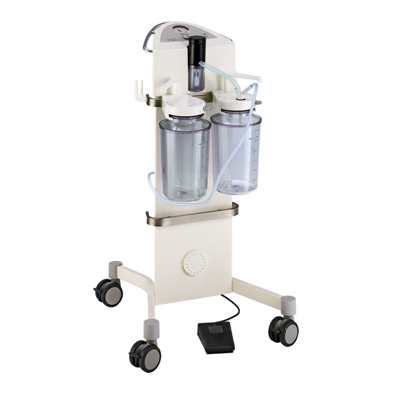
Page 10: Overview
Introduction Overview Overview 1.3.1 Overview of TWISTA SP 1070 -0,6 -0,4 -0,8 -0,2 -1,0 mmHg 1 1 0 0 TWISTA SILENT POWER 1070 1 1 1 1 1 1 2 2 1 1 3 3 1 1 5 5 1 1 4 4 Fig. -
Page 11: Basic Requirements
Introduction Basic requirements Basic requirements 1.4.1 Use in accordance with the intended purpose Product As per Annex IX to the Medical Devices Directive 93/42/EEC, this product belongs to class IIa. In accordance with this directive the product may only be used by persons who have been instructed how to use this product by an authorised person. -
Page 12: For Use In Cardiac Surgery And Surgery Of The Central Nervous System (Cns)
Introduction Basic requirements Contraindications: The TWISTA SP 1070 may not be used for the following purposes: • Outside the medical sector • In the home care sector • Being operated directly by the patient • For vacuum extraction • For smoke evacuation •... -
Page 13: Interface Description
Introduction Basic requirements TWISTA SP 1070 127 V; 60 Hz (REF 5752 1559) • Basic equipment • Mains cable • Foot switch • Filter papers (10 pieces) • Allen key (REF 5750 4687) 1.4.5 Interface description 1.4.5.1 Hydrophobic bacterial and viral filter NOTE The use of a hydrophobic bacterial and viral filter is not necessary if a suitable hydrophobic bacterial and viral filter is integrated for a specific purpose in the septic... -
Page 14: Suction Tube
Introduction Basic requirements Technical specifications • Vacuum resistant down to -95 kPa (may not collapse) Prerequisites • Must be equipped with an overflow protection device or must be connected to an external overflow protection system. • Low leakage. • Capacity of 1 l to 5 l. •... -
Page 15: Application Sets
Introduction Basic requirements 1.4.5.8 Application sets Application sets augment the basic unit. Application sets can be configured as required, using individual accessories. Prerequisites • Suitable connection tubes must be selected. • The interface descriptions for the aspirator must be observed. 1.4.5.9 Switch valve The switch valve is used to switch between two septic fluid jars. -
Page 16: Safety Notes
Safety notes General safety notes Safety notes General safety notes DANGER! Danger to life! Danger due to unauthorised modifications. The product may not be modified. DANGER! Explosion hazard! The product does not have explosion protection and is not approved for use in Class AP-M hazardous locations. -
Page 17: Product Safety Notes
Safety notes Product safety notes DANGER! Danger to life! Electric shock resulting from an object being inserted from the outside into the case and its making contact with live components. Never insert any objects into the case. DANGER! Potentially fatal due to electrical shock! The product may only be connected to voltage supplies with protected earth connections. - Page 18 Safety notes Product safety notes DANGER! Infection hazard! The bacterial filter paper provides additional protection against contamination of the ambient air. Do not operate the aspirator without a bacterial filter paper. CAUTION! Property damage due to oversuction! The product may only be operated with the overflow protection in place as otherwise oversuction could occur.
-
Page 19: Initial Operation
Initial operation General Initial operation General WARNING! Risk of injury! ATMOS products may be used only when fully functional. Check to ensure that the ATMOS product is fully functional and in good working order prior to use. ATMOS recommends always having an alternative suction option ready. -
Page 20: Mounting The Stand
Initial operation Mounting the stand Mounting the stand CAUTION! Property damage! Improperly mounted stands cause danger of tipping over. Make sure that you have a right and a left stand and that the stands are mounted properly. Position for installation ... - Page 21 Initial operation Mounting the stand Mounting the first stand Place the red point of the stand (1) on the red point of the basic equipment (2). The longer part of the stand (3) must point to the floor. ...
- Page 22 Initial operation Mounting the stand Aligning and fixing stands Position the aspirator (1) on an even surface. The longer parts of the stand (2) are located on the front of the equipment. Stands are aligned. Hand tighten screws to maximum with Allen key (3).
-
Page 23: Mounting The Tube Holder
Initial operation Mounting the tube holder Mounting the tube holder The tube holders are screwed into place on the right and left sides of the equipment rail. Press the tube holder (1) with the open side upwards to the equipment rail (2). ... -
Page 24: Mounting The Mechanical Overflow Protection Device (Ref 5752 1775)
Initial operation Overflow protection device/tube connector CAUTION! Property damage! If the float of the overflow protection device is not fitted properly or if it is not used, liquid may enter the aspirator and damage it. Ensure correct seat of the float. 3.6.1 Mounting the mechanical overflow protection device (REF 5752 1775) Mounting the overflow protection device... -
Page 25: Mounting The Hydrophobic Bacterial And Viral Filter (Ref 5752 1783) In The Mechanical Overflow Protection Device (Ref 5752 1775)
Initial operation Overflow protection device/tube connector 3.6.2 Mounting the hydrophobic bacterial and viral filter (REF 5752 1783) in the mechanical overflow protection device (REF 5752 1775) The overflow protection device offers the possibility to subsequently connect a hydrophobic bacterial and viral filter to the mechanical overflow protection. It is required, if the aspirated gas contains aerosols. -
Page 26: Mounting Point For Rail Clamp (Ref 5752 2048)
Initial operation Mounting point for rail clamp (REF 5752 2048) Insert the tube connector (1) into the opening (2) on the equipment. Fig. 13: Inserting the tube connector Mounting point for rail clamp (REF 5752 2048) Containers with an equipment mount may be attached to the rail clamp mount. Attaching the rail clamp ... -
Page 27: Mounting The Switch Valve (Ref 5752 2049)
Initial operation Mounting the switch valve (REF 5752 2049) Mounting the switch valve (REF 5752 2049) The vacuum shift is used to switch between two septic fluid jars. Mounting the switch valve Attaching rail clamp [ Page 26]. Attach equipment mount (1) of switch valve to rail clamp (2). -
Page 28: Mounting The Tube To The Overflow Protection Device
Initial operation Mounting the tubes 3.9.1 Mounting the tube to the overflow protection device Attach the connection tube (1) to the tube connector (2) of the overflow protection device. Fig. 16: Overflow protection device 3.9.2 Mounting the tube to the tube connector ... -
Page 29: Tube Connection Of Overflow Protection Device With Septic Fluid Jar Cap (Ref 5750 0390)
Initial operation Mounting the tubes 3.9.3 Tube connection of overflow protection device with septic fluid jar cap (REF 5750 0390) Attach the connection tube (1) to the straight tube connector (2) of the cap plug. Attach the suction tube (3) to the second tube connector (4) of the cap plug. -
Page 30: Tube Connection Of Overflow Protection Device With Septic Fluid Jar Cap (Ref 5752 5432)
Initial operation Mounting the tubes 3.9.5 Tube connection of overflow protection device with septic fluid jar cap (REF 5752 5432) Plug adapter (REF 5752 2295) (1) onto the connection tube (2). Insert the adapter with the connection tube into the septic fluid jar cap (3). -
Page 31: Connecting/Disconnecting The Mains Cable
Initial operation Connecting/disconnecting the mains cable Attach the connection tube (4) to the left tube connector (5) of the vacuum shift. Attach the other end of the connection tube to the black tube connector (6) on the septic fluid jar cap. ... - Page 32 Initial operation Connecting/disconnecting the mains cable Securing mains cable Secure the mains cable with the bracket (4) on the aspirator. Connect the potential equalisation cable to the equalisation pin (5). Disconnecting the mains cable Pull the bracket up. ...
-
Page 33: Operation
Operation Functional test Operation Functional test Prior to using the system, the operator should check that the product is fully functional and in good condition. NOTE Connecting several septic fluid jars in series can cause delayed suction effect and reduced suction power. Prior to each use, carry out the following functionality check: •... - Page 34 Operation Suction WARNING! Risk of infection due to using no or a defective hydrophobic bacterial and viral filter. Secretions enter the aspirator during aspiration. Stop using the aspirator. Clean and disinfect the aspirator and have it repaired by a service technician authorised by ATMOS to do so. WARNING! Backflow of aspirated secretion! In the event of oversuction, the aspirated secretion may flow back to the patient if...
-
Page 35: Switching On The Aspirator
Operation Suction 4.2.1 Switching on the aspirator Switch on the aspirator (1). The green power control light (2) is illuminated. Fig. 25: Switching on the aspirator 4.2.2 Setting the vacuum level NOTE Refer to the troubleshooting guide if there is insufficient vacuum or no vacuum at all. -
Page 36: Operating The Footswitch
Operation Replacing the bacterial filter paper 4.2.3 Operating the footswitch The appliance can be transferred to energy-saving standby mode using the foot switch. Operate the foot switch. Aspirator is set to stand-by mode. Yellow light emitting diode (1) is illuminated. - Page 37 Operation Replacing the bacterial filter paper NOTE Using the aspirator requires daily replacement of the bacterial filter paper. Screw off cap (1). Remove used bacterial filter paper (2). Clean and wipe-disinfect the cap. Insert new bacterial filter paper into the cap. ...
-
Page 38: Taking The Unit Out Of Operation
Taking the unit out of operation Completing the aspiration process Taking the unit out of operation Completing the aspiration process Remove the tube from the patient. Switch off the aspirator. Empty the septic fluid jar. Clean the components. Emptying the septic fluid jar DANGER! Infection hazard! -
Page 39: Disassembly
Taking the unit out of operation Disassembly Disassembly 5.3.1 Detaching tubes The disassembly of the tubes is described using the septic fluid jar cap (REF 5750 5362) as an example. Switch off the aspirator. Remove the connection tube (1) from the black connection of the septic fluid jar cap. -
Page 40: Cleaning And Disinfection
Cleaning and disinfection Cleaning Cleaning and disinfection Cleaning 6.1.1 General All the components in the aspirator which come into contact with septic fluid must be cleaned and disinfected after each use. DANGER! Danger to life! Electric shock! Remove the mains plug from the socket before cleaning / disinfection. DANGER! Danger to life! Electric shock! -
Page 41: General
Cleaning and disinfection Cleaning CAUTION! Improper cleaning and disinfection can cause property damage! Use only as much detergent and disinfectant as required. CAUTION! Improper cleaning and disinfection can cause property damage! Perform visual and functional inspections after each cleaning and disinfection process. -
Page 42: Cleaning Procedure
Cleaning and disinfection Disinfection NOTE Use only all-purpose cleaners which are slightly alkaline (soap solution) and which contain surfactants and phosphates as the active cleaning agents. In the event of heavily contaminated surfaces, use concentrated multi-purpose detergent. 6.1.3 Cleaning procedure ... -
Page 43: Suitable Disinfectants
Cleaning and disinfection Disinfection 6.2.2 Suitable disinfectants Only surface disinfectants based on the following combinations of active ingredients may be used for disinfection: • Aldehydes • Quaternary compounds • Guanidine derivatives Ingredient group Active ingredients Aldehydes 2-ethyl-1-hexanal, formaldehyde, glutardialdehyde, glyoxal, o-phthaldialdehyde, succinaldehyde Quaternary compounds Alkyl-didecyl-polyoxethyl ammonium propionate, alkyl-dimethyl-... - Page 44 Cleaning and disinfection Disinfection Components In solution Wipe / spray disinfection Housing of overflow protection device Disposable Hydrophobic bacterial and viral filter (REF 5752 1783) Bacterial filter paper When in use, must be replaced daily After exposure (as prescribed in the manufacturer's instructions), rinse components thoroughly with water and dry them afterwards.
-
Page 45: Maintenance
Maintenance General Maintenance General Maintenance, repairs and period tests may only be carried out by persons who have the appropriate technical knowledge and are familiar with the product. To carry out these measures, the person must have the necessary test devices and original spare parts. ATMOS recommends: Work should be carried out by an authorised ATMOS service partner. -
Page 46: Malfunctions And Troubleshooting
Maintenance Malfunctions and troubleshooting Suggestion: Inspection Defects are present No defects Has the product been cleaned Do not use the product any and disinfected according to longer. the hygiene guideline? Clean and disinfect the product according to the guidelines. Comment: Are there cracks in the ... -
Page 47: Replace Mains Fuse
Maintenance Replace mains fuse No. Malfunction Cause Remedy Aspirator working but The vacuum gauge is Have the equipment repaired by vacuum gauge indicates defective. a service technician authorised no vacuum. by ATMOS. Reduced / no flow rate Septic fluid jar cap is not in Position septic fluid jar cap the correct position. - Page 48 Maintenance Replace mains fuse CAUTION! Property damage! You may only use fuses of the following type: • 2 x T 1.6 A H / 250 V for nominal voltage 230 V AC (REF 5752 1554) • 2 x T 2.5 A H / 250 V for nominal voltage 127 V AC (REF 5752 1559) ...
-
Page 49: Repairs
Maintenance Repairs Repairs The following issues may require repairs by the manufacturer or an authorised service partner: • Liquid has penetrated the device. • The performance has significantly decreased. • Inexplicable notifications appear. • Abnormal noises occur. • Functional faults cannot be rectified according to the measures in chapter Malfunctions and troubleshooting [... -
Page 50: Sending In The Device
Maintenance Sending in the device Sending in the device Remove and properly dispose of consumables. Clean and disinfect the product and accessories according to the operating instructions. Place used accessories with the product. Fill in the form QD 434 „Delivery complaint / return shipment“ and the respective decontamination certificate in a envelope. -
Page 51: Technical Specifications
Technical specifications General Technical specifications General Classification as per Annex IX to Directive 93/42/EEC Class IIa Type of protection against electric shock Class I (IEC 60601-1) Level of protection against electrical shock Type BF* (IEC 60601-1) Protection against ingress of liquids IP X1 (IEC 60601-1) Accuracy class of vacuum gauge Year of manufacture... -
Page 52: Twista Sp 1070 127 V 60 Hz
Technical specifications Dimensions and weight 8.3.2 TWISTA SP 1070 127 V 60 Hz Voltage 127 V AC Frequency 60 Hz Vacuum NN** -90 kPa Maximum current consumption 1.6 A Fuses T 2.5 AH / 250 V Displacement 68 l/min ±7 l Maximum power consumption 210 VA Operating mode... -
Page 53: Resistance To Electromagnetic Interference
Technical specifications Electromagnetic compatibility (EMC) RF emissions Group 1 The product uses RF energy exclusively for its own internal functions. Consequently its CISPR 11 RF emission levels are very low and it is improbable that interference will be caused in nearby electronic equipment. Class B The product is intended for use in all facilities, to include residential areas, and in... -
Page 54: Resistance To Electromagnetic Interference, Non-Life-Sustaining Equipment
Technical specifications Electromagnetic compatibility (EMC) Magnetic field of 3 A/m 3 A/m The magnetic fields generat- the supply fre- ed at line frequency should quency (50 / correspond to values typical- 60 Hz) ly found in commercial or hospital environments. IEC 61000-4-8 Note: U is the AC mains voltage prior to application of test levels. -
Page 55: Recommended Separation Distances
Technical specifications Electromagnetic compatibility (EMC) Notes: At 80 MHz and 800 MHz the higher frequency range is applicable. These guidelines may not be applicable in all situations. The propagation of electromagnetic emissions will be affected by the absorptive and reflective properties of the buildings, objects and persons. a) The field strength of stationary transmitters such as the base stations for radio (cellular/ cordless) telephones and land mobile radios, amateur radio, and AM and FM broadcast and TV broadcast can, theoretically, not be determined exactly in advance. - Page 56 Technical specifications Electromagnetic compatibility (EMC) Transmitter rated Separation distance as per transmission frequency [m] power [W] 150 kHz to 80 MHz 80 MHz to 800 MHz 800 MHz to 2.5 GHz When dealing with transmitters for which no rated output is indicated in the table above, the distance can be ascertained, using the equation associated with the appropriate column, where P is the transmitter's maximum rated power in watts (W) as specified by the manufacturer of the transmitter.
-
Page 57: Approved Accessories
Approved accessories Accessories Approved accessories Accessories 5752 1775 Mechanical overflow protection device with chamber for hydrophobic bacterial and virus filter 5750 5228 Septic fluid glas jar 5.0 Iitre 5750 5227 Septic fluid glas jar 2.5 Iitre 5750 5297 Septic fluid jar 3.0 Iitre PSU 5750 5296 Septic fluid jar 1.0 Iitre PSU 5752 5656... -
Page 58: Twista Sp 1070
Approved accessories TWISTA SP 1070 TWISTA SP 1070 5752 5671 TWISTA SP 1070 complete unit / 2 x 4 litre / PSU 5752 5672 TWISTA SP 1070 complete unit / 2 x 4 litre / PC 5752 4855 TWISTA SP 1070 complete unit / 2 x 3 litre Tab. - Page 59 Notes...
- Page 60 Manufacturer: ATMOS MedizinTechnik GmbH & Co. KG Ludwig-Kegel-Str. 16 79853 Lenzkirch GERMANY Phone: +49 7653 689-0 www.atmosmed.com...
Need help?
Do you have a question about the WISTA SP 1070 and is the answer not in the manual?
Questions and answers