Table of Contents
Advertisement
Quick Links
Advertisement
Table of Contents

Related Manuals for MEDAP S VAC INT


Summary of Contents for MEDAP S VAC INT
- Page 1 OPERATING INSTRUCTIONS MEDAP TAPPING UNIT S VAC INT GA 5752 5727 GB 03...
- Page 2 Subject to technical modification! Illustrations and technical specifications may vary slightly from those in these operating instructions as a result of ongoing product development. V03 2020-07 GA 5752 5727 GB 03...
-
Page 3: Table Of Contents
1.2.5.2 ATMOS products ....................... 8 Overview ..............................9 1.3.1 S VAC INT ............................ 9 1.3.2 S VAC INT versions ........................10 Basic requirements ........................... 10 1.4.1 Use in accordance with the intended purpose ................10 1.4.2 Applicable standards ........................10 1.4.3... - Page 4 Table of contents Mounting accessories ..........................18 3.3.1 General ............................18 3.3.2 Mounting the mechanical overflow protection ................19 3.3.3 Connection of the mechanical overflow protection ..............19 3.3.4 Connection of hydrophobic bacterial and viral filter ..............20 Operation ..............................21 Function test .............................
- Page 5 Table of contents Approved accessories ........................... 34 Accessories .............................. 34 Consumables ............................34 GA 5752 5727 GB 03...
-
Page 6: Introduction
Introduction Foreword Introduction Foreword Your facility has selected the leading-edge medical technology made by ATMOS. We sincerely appreciate the trust you have placed in us. How to use these operating instructions These operating instructions are provided to familiarise you with the features of this ATMOS product. -
Page 7: Definitions
Introduction How to use these operating instructions 1.2.3 Definitions 1.2.3.1 Design of safety notes Pictogram Descriptor Text The text for the safety note DANGER! describes the type of risk and Indicates a direct and immediate risk to how to avert it. persons which may be fatal or result in most serious injury. -
Page 8: Disposal
Introduction How to use these operating instructions Symbols Identification Labelling in compliance with the IEC 60601-1 standard. Symbol for ‘Follow operating instructions’. Labelling in compliance with the ISO 15223-1 standard. Symbol for ‘Name and address of the manufacturer as well as date of manufacture’. -
Page 9: Overview
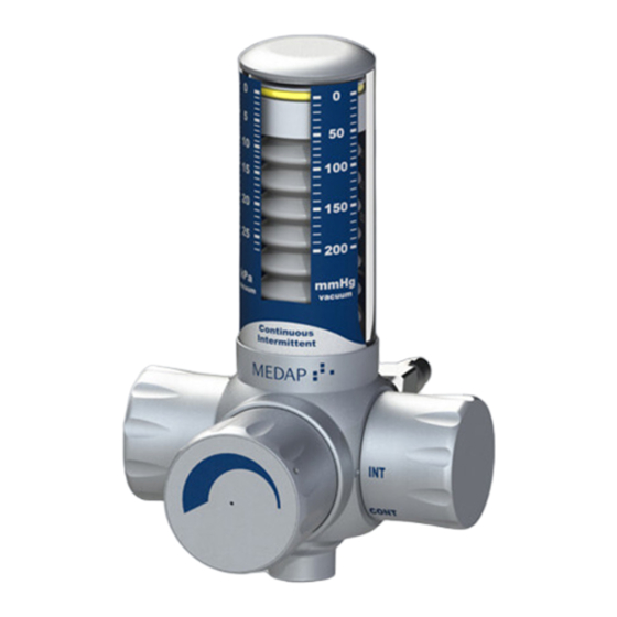
Introduction Overview Overview 1.3.1 S VAC INT Fig. 1: Overview of S VAC INT 1 S VAC INT 6 Terminal unit 2 Vacuum indicator 7 Air inlet 3 Control valve 8 Mechanical overflow protection 4 Selector switch OFF - CONT - INT... -
Page 10: S Vac Int Versions
Introduction Basic requirements 1.3.2 S VAC INT versions Fig. 2: Overview of S VAC INT versions 1 Version A 4 Version B Tapping unit with integrated gas pin Tapping unit with rail clamp and NIST connection 2 Gas pin 3 Terminal unit... -
Page 11: Intended Purpose
Drainage and temporary collection of body fluids. For the supply of function: vacuum, S VAC INT is connected to a terminal unit for vacuum of a central medical gas supply system (−100 kPa to −60 kPa). A septic fluid jar, which has to be used, allows for temporary collection of drained body fluids. -
Page 12: S Vac Int Versions
Version B: Tapping unit with rail clamp and NIST connection • S VAC INT is designed for mounting onto a 25−35 x 10 mm equipment rail in accordance with DIN EN 19054 and is supplied from a terminal unit for vacuum via a NIST connection with a connection tube with gas probe. -
Page 13: Septic Fluid Jar Including Septic Fluid Jar Cap
Introduction Basic requirements Prerequisites • Pore size ≤ 1.0 μ. • The tube connector must match the tube being used. • The hydrophobic bacterial and viral filter must close tightly against water passage at an abso- lute pressure of up to 10 kPa. •... -
Page 14: Mechanical Overflow Protection
Introduction Basic requirements 1.4.5.7 Mechanical overflow protection The mechanical overflow protection device protects the product against the ingress of particles and fluid. The tube connector must match the vacuum connection tube. GA 5752 5727 GB 03... -
Page 15: Safety Notes
Safety notes General safety notes Safety notes General safety notes DANGER! Danger to life! Danger due to unauthorised modifications. The product may not be modified. WARNING! Risk of injury! Hazard resulting from incorrect handling. Be absolutely sure to observe the operating instructions for all the products used in the configuration. - Page 16 Safety notes Product safety notes WARNING! Impacts! Impacts may cause damage to sensitive, precision mechanical components. Do not expose the product to impacts. WARNING! Measuring accuracy / oversuction! The product may only be operated in a vertical position. WARNING! Foaming! Foam may be created when extracting secretion.
-
Page 17: Initial Operation
Initial operation Product testing Initial operation Product testing DANGER! Product testing! Only product parts which are in perfect condition can ensure proper functioning of the product. The product parts will thus have to be carefully inspected before mounting. WARNING! Infection hazard! Contaminated components may endanger the health of staff and patients. -
Page 18: Version B
Initial operation Mounting accessories 3.2.3 Version B Tapping units with rail clamp and NIST connection Position the rail clamp (1) at a slight angle with the upper edge of the guide groove on the equipment rail (2) and then press it against the equipment rail and allow it to click into place. -
Page 19: Mounting The Mechanical Overflow Protection
Initial operation Mounting accessories 3.3.2 Mounting the mechanical overflow protection Mounting the mechanical overflow protection Insert the float (1) into the overflow container (2). Fit the sealing ring (3) onto the cap (4). Insert the cap into the overflow container. ... -
Page 20: Connection Of Hydrophobic Bacterial And Viral Filter
Initial operation Mounting accessories 3.3.4 Connection of hydrophobic bacterial and viral filter Mounting the hydrophobic bacterial and viral filter Remove the grub screw from the adapter (1) with an Allen key. Insert the adapter (1) for the hydrophobic filter directly into the tapping unit (2) and turn. -
Page 21: Operation
Operation Function test Operation Function test Prior to using the system, the operator should check that the product is fully functional and in good condition. NOTE Connecting several septic fluid jars in series can cause delayed suction effect and reduced suction power. Prior to each use, carry out the following functionality checks: Version A: Tapping unit with integrated gas pin •... -
Page 22: Setting The Vacuum Level
Operation Setting the vacuum level The selector switch has three setting possibilities Arrow (1) beside the selector switch (2) points to OFF: No aspiration. Arrow (1) beside the selector switch (2) points to CONT: Continuous aspiration. Arrow (1) beside the selector switch (2) points to INT: Intermittent aspiration. - Page 23 Operation Setting the vacuum level Setting the vacuum for treatment Set the selector switch (1) to position OFF and connect the tapping unit [ page 17]. Turn the control valve (2) clockwise and close as far as it will go. ...
-
Page 24: Taking The Unit Out Of Operation
Taking the unit out of operation Completing the aspiration process Taking the unit out of operation Completing the aspiration process NOTE Please refer to the manufacturer’s instructions for the particular terminal unit for information on detaching the gas probe from the terminal unit. ... -
Page 25: Dismantling The Mechanical Overflow Protection
Taking the unit out of operation Disassembly 5.2.2 Dismantling the mechanical overflow protection Remove the particle filter (1) from the cap (2). Remove the cap from the overflow container (3). Remove the sealing ring (4) from the cap (2). -
Page 26: Cleaning And Disinfection
Cleaning and disinfection General Cleaning and disinfection General The product must be wipe or spray disinfected after every use. DANGER! Risk due to incorrect use of detergents and disinfectants! It is strictly advised to observe the manufacturer’s instructions regarding how to use the detergents and disinfectants as well as to observe the valid hospital hygiene rules. -
Page 27: Cleaning
Cleaning and disinfection Cleaning Cleaning 6.2.1 General NOTE Use only all-purpose cleaners which are slightly alkaline (soap solution) and contain surfactants and phosphates as the active cleaning agents. In the event of heavily contaminated surfaces, use concentrated all-purpose detergent. CAUTION! Improper cleaning can cause property damage! Residues of physiological saline solutions (e.g. -
Page 28: Suitable Disinfectants
Cleaning and disinfection Disinfection CAUTION! Material damage due to excessive exposure times! Exceeding the specified exposure time of the disinfectant may damage the surfaces. Observe the exposure time specified by the disinfectant manufacturer. 6.3.2 Suitable disinfectants Only surface disinfectants based on the following combinations of active ingredients may be used for disinfection: •... -
Page 29: Product-Specific Safety Notes
Cleaning and disinfection Product-specific safety notes Components Wipe, spray disinfection S VAC INT Mechanical overflow protection After exposure (as prescribed in the manufacturer's instructions), remove disinfectant residues from the components using a moist cloth and dry them afterwards. Product-specific safety notes... -
Page 30: Maintenance
Maintenance General Maintenance General Maintenance, repairs and periodic tests may only be carried out by persons who have the appropriate technical knowledge and are familiar with the product. To carry out these measures, the person must have the necessary test devices and original spare parts. ATMOS recommends: Work should be carried out by an authorised ATMOS service partner. -
Page 31: Repairs
Maintenance Repairs Defect Source of malfunction Troubleshooting No switching between Setting was altered Contact Technical Service aspiration and non-aspiration in the selector switch setting Oversuction of product Tapping unit mounted at an Operate tapping unit in a vertical despite protective system angle position only Overflow protection device... -
Page 32: Type Plate Position
Maintenance Type plate position Type plate position Position of the type plate (1). Fig. 11: Type plate position Sending in the device Remove and properly dispose of consumables. Clean and disinfect the product and accessories according to the operating instructions. ... -
Page 33: Technical Specifications
Technical specifications General Technical specifications General Classification as per Annex IX to Directive 93/42/EEC Class IIa Technical specifications Vacuum regulation range 0 to −26 kPa* Flow rate CONT (Freeflow)** 60 l/min Flow rate INT (Freeflow)** 9 l/min Accuracy ±5% Intermittent aspiration: Ratio aspiration : non-aspiration*** Approx. - Page 34 Approved accessories Accessories Approved accessories The following accessories are not part of the scope of delivery and must be ordered separately: Accessories 5752 5632 Mechanical overflow protection 5752 5634 Adapter for the hydrophobic bacterial and viral filter Tab. 6: Accessories Consumables 5752 5635 Hydrophobic bacterial and viral filter (disposable)
- Page 35 Notes...
- Page 36 Manufacturer: ATMOS MedizinTechnik GmbH & Co. KG Ludwig-Kegel-Str. 16 79853 Lenzkirch GERMANY Phone: +49 7653 689-0 www.atmosmed.com...
Need help?
Do you have a question about the S VAC INT and is the answer not in the manual?
Questions and answers