
Related Manuals for Endress+Hauser Magphant


Summary of Contents for Endress+Hauser Magphant
- Page 1 Products Solutions Services BA00025D/06/EN/05.20 71463741 2020-02-03 Valid as of version 01.00.zz (Device firmware) Operating Instructions Magphant Electromagnetic flowmeter...
- Page 2 • The manufacturer reserves the right to modify technical data without prior notice. Your Endress+Hauser Sales Center will supply you with current information and updates to these instructions. Endress+Hauser...
-
Page 3: Table Of Contents
Storage and transport ... . . 13 12.2 Endress+Hauser services ....31 Storage conditions ..... 13 Repair . - Page 4 Table of contents Magphant 15.9 Process ......37 15.10 Mechanical construction ....
-
Page 5: About This Document
Magphant About this document About this document Document function These Operating Instructions contain all the information that is required in various phases of the life cycle of the device: from product identification, incoming acceptance and storage, to mounting, connection, operation and commissioning through to troubleshooting, maintenance and disposal. -
Page 6: Symbols For Certain Types Of Information
• W@M Device Viewer (www.endress.com/deviceviewer): Enter the serial number from nameplate • Endress+Hauser Operations App: Enter the serial number from the nameplate or scan the 2D matrix code (QR code) on the nameplate Detailed list of the individual documents along with the documentation code... -
Page 7: Standard Documentation
Magphant About this document 1.3.1 Standard documentation Document type Purpose and content of the document Technical Information Planning aid for your device The document contains all the technical data on the device and provides an overview of the accessories and other products that can be ordered for the device. -
Page 8: Safety Instructions
Safety instructions Magphant Safety instructions Requirements for the personnel The personnel for installation, commissioning, diagnostics and maintenance must fulfill the following requirements: ‣ Trained, qualified specialists must have a relevant qualification for this specific function and task. ‣ Are authorized by the plant owner/operator. -
Page 9: Workplace Safety
Verification for borderline cases: ‣ For special fluids and fluids for cleaning, Endress+Hauser is glad to provide assistance in verifying the corrosion resistance of fluid-wetted materials, but does not accept any warranty or liability as minute changes in the temperature, concentration or level of contamination in the process can alter the corrosion resistance properties. -
Page 10: Product Description
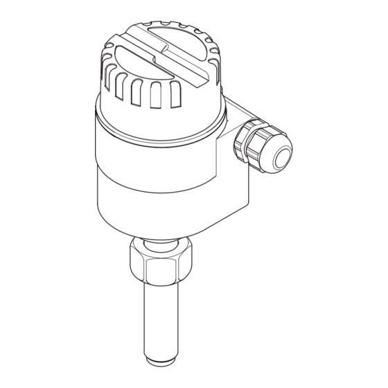
Product description Magphant Product description The device consists of a transmitter and a sensor. The device is available as a compact version: The transmitter and sensor form a mechanical unit. Product design A0040146 1 Important components of a measuring device... -
Page 11: Incoming Acceptance And Product
Technical Documentation present? • If one of the conditions is not satisfied, contact your Endress+Hauser Sales Center. • Depending on the device version, the CD-ROM might not be part of the delivery! The Technical Documentation is available via the Internet or via the Endress+Hauser Operations App, see the "Product identification"... -
Page 12: Symbols On Measuring Device
7 sections • The W@M Device Viewer: enter the serial number from the nameplate (www.endress.com/deviceviewer) • The Endress+Hauser Operations App: Enter the serial number from the nameplate or scan the 2-D matrix code (QR code) on the nameplate. 4.2.1... -
Page 13: Storage And Transport
Magphant Storage and transport Storage and transport Storage conditions Observe the following notes for storage: ‣ Store in the original packaging to ensure protection from shock. ‣ Do not remove the protection cap mounted on the sensing element. It prevents mechanical damage and contamination in the measuring tube. - Page 14 Installation Magphant Preferably install the sensor in an ascending pipe, and ensure a sufficient distance to the next pipe elbow: h ≥ 5 × DN Installation position Installation position Recommendation Vertical orientation A0017337 Horizontal orientation, transmitter head A0015589 Horizontal orientation, transmitter head...
- Page 15 Magphant Installation A0040155 2 Position of electrode axis Axis of electrodes Axis of cable glands Inlet and outlet runs If possible, install the sensor upstream from fittings such as valves, T-pieces or elbows. Observe the following inlet and outlet runs to comply with accuracy specifications: 5…10 ×...
- Page 16 Installation Magphant M30 x 2 27 mm 23 (0.9) -0.10 (0.004) -0.30 (0.01) 30 (1.2) A0040150 3 Welding socket for pipes DN 25. Engineering unit mm (in) ‣ Pipe ≥DN 40: With the marking (according to the nominal diameter) flush against the outer wall of the pipe, weld the welding socket at right angles to the axis of the piping.
- Page 17 Magphant Installation 40 (1.6) ¼" NPSM 40 (1.6) 50 (2.0) A0040243 5 Installation conditions for plastic welding socket. Engineering unit mm (in) Plastic welding socket To be determined Pipe wall thickness Immersion depth of plastic welding socket (please refer to the table below for dimension E)
-
Page 18: Environment And Process Requirements
T-fitting. The T-fitting can be purchased from the Georg Fischer company. PVC, PP and PE T-fittings are available. Only use the Magphant version for device installation in plastic pipes (order code for "Process connection", option 5 "Adapter, plastic pipe, 316L, NBR"). - Page 19 Magphant Installation Mounting the sensor in a steel pipe NOTICE Damage to the sensor tip. ‣ When inserting the sensor into the welding socket, care must be taken to ensure the sensor tip is not damaged. 1. Taking the flow direction → 14 into consideration, insert the sensor into the welding socket and tighten the metal union nut by hand.
-
Page 20: Post-Installation Check
Installation Magphant 36 mm 27 mm A0040153 8 Mounting the adapter piece on the sensor Adapter piece made of stainless steel, 1.4435 (F316L) Plastic union nut Metal union nut Post-installation check Is the device undamaged (visual inspection)? Does the measuring device conform to the measuring point specifications? ... -
Page 21: Electrical Connection
Magphant Electrical connection Electrical connection NOTICE The measuring device does not have an internal circuit breaker. ‣ For this reason, assign the measuring device a switch or power-circuit breaker so that the power supply line can be easily disconnected from the mains. -
Page 22: Preparing The Measuring Device
Electrical connection Magphant 7.1.4 Preparing the measuring device NOTICE Insufficient sealing of the housing! Operational reliability of the measuring device could be compromised. ‣ Use suitable cable glands corresponding to the degree of protection. 1. Remove dummy plug if present. -
Page 23: Ensuring Potential Equalization
Magphant Electrical connection Ensuring potential equalization 7.3.1 Requirements CAUTION Electrode damage can result in the complete failure of the device! ‣ Same electrical potential for the fluid and sensor ‣ Company-internal grounding concepts ‣ Pipe material and grounding ‣ Keep the grounding cable as short as possible 7.3.2... -
Page 24: Post-Connection Check
Electrical connection Magphant 5. To ensure that moisture does not enter the cable entry: Route the cable so that it loops down before the cable entry ("water trap"). A0029278 6. Insert dummy plugs into unused cable entries. Post-connection check Are cables or the device undamaged (visual inspection)? ... -
Page 25: Operation Options
Magphant Operation options Operation options Access via local display Customized settings can be recorded on the operating and display interface. 8.1.1 Operating and display elements 1 2 3 4 A0040158 11 Operating and display elements Test mode Current output time constant and relay hold time Relay functions Min./max. - Page 26 Operation options Magphant Operating and display Meaning element Relay functions If all functions are operating correctly, the relay is energized. The relay is de- energized as soon as an error or alarm occurs: "Limit" switch position The relay is de-energized and the red LED is lit if the limit value is exceeded or undershot (this depends on the min./max.
-
Page 27: Commissioning
Magphant Commissioning Commissioning Function check Before commissioning the measuring device: ‣ Make sure that the post-installation and post-connection checks have been performed. • "Post-installation check" checklist → 20 • "Post-connection check" checklist → 24 Switching on the measuring device Once the supply voltage has been switched on, the measuring device adopts the normal mode. -
Page 28: Operation
Operation Magphant Operation Settings can be made at the measuring device with the operating and display interface. Description of the operating and display elements → 25. Endress+Hauser... -
Page 29: Diagnostics And Troubleshooting
Magphant Diagnostics and troubleshooting Diagnostics and troubleshooting 11.1 Diagnostic behavior Error messages are reported via the current output and relay output (depending on the relay function that is configured). In addition, the red LED flashes to indicate the limit value or error condition. - Page 30 Diagnostics and troubleshooting Magphant A0040157 9. Release the ground cable. 10. Replace the electronics module. 11. Install the new electronics module in the reverse order. Endress+Hauser...
-
Page 31: Maintenance
• Follow the instructions in the "Installation" section when removing the sensor→ 8. 12.2 Endress+Hauser services Endress+Hauser offers a wide variety of services for maintenance such as recalibration, maintenance service or device tests. Your Endress+Hauser Sales Center can provide detailed information on the services. -
Page 32: Repair
Is located on the nameplate of the device. 13.2 Endress+Hauser services Endress+Hauser offers a wide range of services. Your Endress+Hauser Sales Center can provide detailed information on the services. 13.3 Return The requirements for safe device return can vary depending on the device type and national legislation. -
Page 33: Accessories
Various accessories are available for the device, and can be ordered with the device or at a later stage from Endress+Hauser. An up-to-date overview of accessories is available from your local Endress+Hauser sales organization or on the product page of the Endress +Hauser website: www.endress.com. -
Page 34: Technical Data
Technical data Magphant Technical data 15.1 Application The measuring device is intended only for the flow measurement of liquids with a minimum conductivity of 20 µS/cm. To ensure that the device remains in proper operating condition for its service life, use the measuring device only for media against which the process-wetted materials are sufficiently resistant. -
Page 35: Input
Magphant Technical data Magphant Transmitter • Materials: Transmitter housing: powder-coated die-cast aluminum • Configuration: Via operating and display elements on the transmitter • Cable entry: M20 × 1.5 cable gland or M20 × 1.5 thread or ½" NPT thread or G ½"... -
Page 36: Output
Technical data Magphant 15.4 Output Output signal Current output 4 to 20 mA Signal mode Active Load 0 to 750 Ω Bidirectional flow The measuring device is able to measure in both flow directions, i.e. it supports measurement bidirectional measurement. The current output is always positive. The relay is activated in both flow directions. -
Page 37: Performance Characteristics
Magphant Technical data 15.6 Performance characteristics Maximum measured error o.r. = of reading ±2 % o.r. at the measuring electrode with local adjustment at flow velocities >1 m/s Reproducibility o.r. = of reading ±2 % o.r. 15.7 Installation Installation conditions →... -
Page 38: 15.10 Mechanical Construction
Technical data Magphant [psi] [bar] [°C] 100 120 [°F] 104 140 176 212 248 A0040248-EN 15.10 Mechanical construction Dimensions 150 (5.9) 99 (3.9) ≈33.5 ≈33.5 (≈1.3) (≈1.3) (0.6) 40 (1.6) 86 ( 3.4) 22 (0.7) A0040250 Dimension H Pipe nominal diameter... -
Page 39: 15.11 Human Interface
Magphant Technical data Pipe nominal diameter H for installation in steel pipes H for installation in plastic pipes mm (in) mm (in) 250 (9.84) 207.5 (8.169) ≥300 (11.81) 201.5 (7.933) Dimensions of welding sockets → 15 Weight 1.2 kg (2.6 lb) -
Page 40: 15.13 Accessories
For an overview of the scope of the associated Technical Documentation, refer to the following: • W@M Device Viewer (www.endress.com/deviceviewer): Enter the serial number from nameplate • Endress+Hauser Operations App: Enter the serial number from the nameplate or scan the 2D matrix code (QR code) on the nameplate Standard documentation Document type... -
Page 41: Index
Magphant Index Index About this document ......5 Field of application Accessories ....... . 33 Residual risks . - Page 42 Index Magphant Post-installation check ..... . . 27 Post-installation check (checklist) ....20 Potential equalization .
- Page 44 www.addresses.endress.com...
Need help?
Do you have a question about the Magphant and is the answer not in the manual?
Questions and answers