Table of Contents

Related Manuals for Endress+Hauser magphant


Summary of Contents for Endress+Hauser magphant
- Page 1 BA 025D/06/e/03.97 magphant No. 50078353 Electromagnetic valid for software-version V1.00.XX Flow Monitor Operating Manual AUTHORIZED DISTRIBUTOR: InstrumentsAndControl.com Houston, Texas USA sales@InstrumentsAndControl.com 832-615-3588...
-
Page 2: Safety Instructions
Ensure that the measuring system is correctly wired up according to the wiring diagrams. The flowmeter is to be grounded. Repairs, Dangerous Chemicals The following procedures must be carried out before a Magphant is sent to Endress+Hauser for repair: •... -
Page 3: Table Of Contents
3.1 General information ..3.2 Connecting the Magphant ..3.3 Commissioning ... 4. Operation ... - Page 4 Magphant Endress+Hauser...
-
Page 5: System Description
1. System description 1.1 Areas of application The Magphant flow monitor provides the plant system with the information needed on flowrate in the piping. The magnetic-inductive measuring principle determines the flow velocity of the conductive liquid at the tip of the sensor. Exceeding the preset switchpoint (limit value) is indicated by a relay contact. -
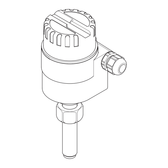
Page 6: Measuring System Design
1. System description Magphant 1.3 Measuring system design A construction overview of the Magphant measuring system is shown in the diagram below. Housing cover can be unscrewed. After opening the cover, operating and dis- play elements as well as the terminal block are easily accessible. -
Page 7: Mounting And Installation
2. Mounting and Installation 2. Mounting and Installation 2.1 Protection type IP 66 (DIN 40050) The Magphant fulfils all the requirements for IP 66. Caution! After successful installation in the field or after replacing an instrument, the following points must always be observed in order to ensure protection to IP 66: •... -
Page 8: Mounting Instructions
Orientation in the piping The Magphant is best mounted in vertical piping. If the piping runs horizontally, then the Magphant is to be mounted to the side. This mounting procedure ensures that the electrodes are always immersed in flowing fluid. -
Page 9: Mounting In Steel Piping
Magphant 2. Mounting and Installation 2.4 Mounting in steel piping The Magphant is mounted in steel piping using the weld stub supplied. Two different versions are available, depending on nominal diameter: Weld stub for DN 25 For DN 25 piping, the weld stub has the appropriate radius to match the diameter. -
Page 10: Mounting In Plastic Piping
3. Tighten the union nut a further approx. turn with a open-ended wrench size 36 mm. Caution! When inserting the Magphant into a weld stub, care must be taken so that the sensor tip is not damaged. Union nut Wrench size 36 mm Wrench size 27 mm Fig. - Page 11 T-section and screw on the plastic union nut tightly by hand. Caution! • Observe the electrode axis orientation (see page 8). • Use only the Magphant version for mounting in plastic piping (different insertion depths!) Metal union nut Plastic union nut...
- Page 12 E = insertion depth of the plastic weld nipple (E can be obtained from the table below) Caution! • Observe the electrode axis orientation (see page 8). • Use only the Magphant version for mounting in plastic piping (different insertion depths!) Detail A Pipe outer diameter 11.4...
-
Page 13: Electrical Connection
3.1 General information Note both the polarity and operating voltage. Warning! Do not install, wire up or dismantle the instrument when the power supply is switched 3.2 Connecting the Magphant Current output 4...20 mA = 750 Ω max. Load R 75 V DC / 0.5 A... -
Page 14: Commissioning
3. Electrical Connection Magphant Potential equalization The Magphant should be connected to ground via the ground terminal at the housing to ensure complete electromagnetic compatibility. Note! Take care that the ground cable is kept as short as possible. 4 mm Cu wire Fig. -
Page 15: Operation
The same function as for "limit", but in addition: The relay de-energises if the flow rate is larger than the measurable value of the Magphant or if an instrument error occurs. The red LED flashes. "Error" has higher priority than "limit". - Page 16 4. Operation Magphant Functions of the operating and display elements Operating and display element Description of function (factory setting) Min./max. fail-safe setting Maximum fail-safe: The relay de-energises if the signal rises above the limit value. The red LED lights up.
-
Page 17: Troubleshooting And Remedies
2 mA 5.2 Checking the electronics The Magphant can be set to a test mode using miniature switch No. 1: Test mode 1. Set test mode switch to "test". 2. Turn the full-scale potentiometer anticlockwise until it comes to the mechanical stop, the current output must now be exactly 20 mA. -
Page 18: Replacing The Electronics Module
5. Troubleshooting and Remedies Magphant 5.3 Replacing the electronics module Warning! Switch off the power supply before unscrewing the cover to the electronics compartment. Carefully remove the Remove excitation electronics module current cable plug Unplug the electrode signal cable plug Fig. -
Page 19: Technical Data
Magphant 6. Technical Data 6. Technical Data 6.1 Dimensions and weight Union nut M 30 x 2 Cable gland Nominal diameter for mounting in for mounting in steel piping plastic piping 237.0 234.0 234.0 230.0 see page 227.0 11 und 12 220.5... -
Page 20: Technical Data
6. Technical Data Magphant 6.2 Technical Data Power supply 24 V DC (20...30 V DC) Power consumption <2.5 W • Current output 4...20 mA, active Outputs The measuring system can measure flow in both directions, i.e. bidirectionally. The current output is always positive. The relay responds to both flow directions. - Page 21 Magphant 6. Technical Data Materials Sensor Sensor tip: PVDF, Viton O-ring Electrodes: 1.4435/316L Sensor sleeve: • 1.4435/316L with 1.4571/316Ti clamp ring for 1.4435/316L weld stub • 1.4435/316L with clamp ring and NBR gasket for St.37/A570 weld stub Housing Aluminium, epoxy powder coated Weld stub 1.4435/316L...
-
Page 22: Index
Index Magphant Index Index Position of the electrode axis ..8 Accuracy ....20 Potential equalization ... . - Page 24 Belorgsintez Canada Philippines Poland Minsk Endress+Hauser Ltd. Endress+Hauser Philippines Inc. Endress+Hauser Polska Sp. z o.o. Tel. (0172) 508473, Fax (0172) 508583 Burlington, Ontario Metro Manila Warszawy Tel. (905) 6819292, Fax (905) 6819444 Tel. (2) 3723601-05, Fax (2) 4121944 Belgium / Luxembourg Tel.
Need help?
Do you have a question about the magphant and is the answer not in the manual?
Questions and answers