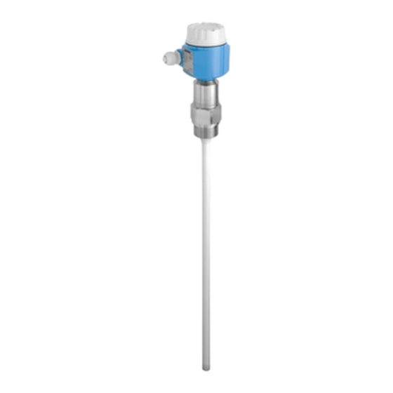
Endress+Hauser Liquicap M FMI51 Operating Instructions Manual
Capacitive level measurement
Hide thumbs
Also See for Liquicap M FMI51:
- Operating instructions manual (114 pages) ,
- Brief operating instructions (36 pages) ,
- Safety instructions (28 pages)

Related Manuals for Endress+Hauser Liquicap M FMI51


Summary of Contents for Endress+Hauser Liquicap M FMI51
- Page 1 Operating Instructions Liquicap M FMI51, FMI52 FEI57C PFM Capacitive Level Measurement BA297F/00/en/12.05 71000300 Valid as of software version: FW: V01.00.00 HW: V01.00...
- Page 2 Brief overview Liquicap M FMI51, FMI52 - Level Measurement - PFM Brief overview For quick and easy commissioning: Safety instructions → Page 6 ff. Explanation of the warning symbols You can find special instructions at the appropriate position in the chapter in question.
- Page 3 Liquicap M FMI51, FMI52 - Level Measurement - PFM Brief overview Brief operating instructions 1. Install probe 2. Wiring Silometer FMC672 FMC672 – – – d2 d4 (+) (–) 2 (+) 1 (–) 3. Switch on power supply 4. Make settings FMC672 >6 m...
- Page 4 Brief overview Liquicap M FMI51, FMI52 - Level Measurement - PFM...
-
Page 5: Table Of Contents
Installation, commissioning and operation ..6 Contact addresses at Endress+Hauser ... 45 Operational safety ......6 Notes on safety conventions and icons . -
Page 6: Safety Instructions
Liquicap M FMI51, FMI52 - Level Measurement - PFM Safety instructions Designated use Liquicap M FMI51, FMI52 are compact, capacitance level transmitters for the continuous measurement of conductive liquids. Installation, commissioning and operation Liquicap M is designed to meet state-of-the-art safety regulations and complies with the applicable requirements and EC Directives. -
Page 7: Notes On Safety Conventions And Icons
Liquicap M FMI51, FMI52 - Level Measurement - PFM Safety instructions Notes on safety conventions and icons To highlight safety-related or alternative processes, we have designed the following safety instructions where every instruction is indicated by a corresponding pictogram. Safety instructions... -
Page 8: Identification
Identification Liquicap M FMI51, FMI52 - Level Measurement - PFM Identification Device designation 2.1.1 Nameplate You can take the following technical data from the nameplate of the device: Order number (see ordering information) Made in Germany, D- 79689 Maulburg Liquicap M L1 = 1000 Order Code.:... - Page 9 Liquicap M FMI51, FMI52 - Level Measurement - PFM Identification 2.1.2 Liquicap M FMI51 Approval: A Non-hazardous area Non-hazardous area, WHG (German Water Resources Act) C ATEX II 1/2 GD EEx ia IIC T6 D ATEX II 1/2 GD EEx ia IIC T6,...
- Page 10 Identification Liquicap M FMI51, FMI52 - Level Measurement - PFM Process connection: NPT 1, 316L, 25 bar Thread ANSI NPT 1½, 316L, 100 bar Thread ANSI Hygiene connection G ¾ 316L, 25 bar Thread ISO2852 Accessories installation, welding neck 316L, 25 bar...
- Page 11 Liquicap M FMI51, FMI52 - Level Measurement - PFM Identification Process connection: 10K 50 RF, 316L Flange JIS B2220 10K 80 RF, 316L Flange JIS B2220 10K 100 RF, 316L Flange JIS B2220 20K 50 RF, 316L Flange JIS B2220...
- Page 12 Identification Liquicap M FMI51, FMI52 - Level Measurement - PFM 2.1.3 Liquicap M FMI52 Approval: A Non-hazardous area Non-hazardous area, WHG (German Water Resources Act) ATEX II 1/2 GD EEx ia IIB T6 ATEX II 1/2 GD EEx ia IIB T6,...
- Page 13 Liquicap M FMI51, FMI52 - Level Measurement - PFM Identification Process connection: EN flanges DN25 PN25/40 A, 316L Flange EN1092-1 (DIN2527 B) DN32 PN25/40 A, 316L Flange EN1092-1 (DIN2527 B) DN40 PN25/40 A, 316L Flange EN1092-1 (DIN2527 B) DN50 PN25/40 A,...
- Page 14 Identification Liquicap M FMI51, FMI52 - Level Measurement - PFM Electronics; output: W Without; Prepared for FEI5x, Flat cover Special version, to be specified Housing: 1 F15 316L IP66, NEMA4X 2 F16 polyester IP66, NEMA4X 3 F17 aluminium IP66, NEMA4X...
-
Page 15: Scope Of Delivery
The device complies with the applicable standards and regulations that are listed in the EC declaration of conformity and thus meets the legal requirements of the EC Directives. Endress+Hauser confirms that the device has been tested successfully by affixing the CE mark. -
Page 16: Installation
Installation Liquicap M FMI51, FMI52 - Level Measurement - PFM Installation Quick installation guide < 80 Nm (G ) ½ < 100 Nm (G ) ¾ < 180 Nm (G1) < 500 Nm (G1 ) ½ ... 270° L00-FMI5xxxx-17-06-xx-xx-001 1.) Screw in the device 2. -
Page 17: Installation Conditions
Liquicap M FMI51, FMI52 - Level Measurement - PFM Installation Installation conditions L00-FMI5xxxx-03-05-xx-en-001... - Page 18 Installation Liquicap M FMI51, FMI52 - Level Measurement - PFM 3.3.1 Housing Note! High cover for housing with display. All dimensions in mm (100 mm = 3.94 in). ø85 max. 76 Polyester housing F16 L00-FMI5xxxx-06-05-xx-en-001 ø76 max. 64 Stainless steel housing F15 L00-FMI5xxxx-06-05-xx-en-003 max.
- Page 19 Liquicap M FMI51, FMI52 - Level Measurement - PFM Installation 3.3.2 Housing extension heights with adapter Polyester housing Stainless steel Aluminium housing Aluminium housing Aluminium housing housing F13* with separate connection compartment T13* L00-FMI5xxxx-06-05-xx-xx-044 L00-FMI5xxxx-06-05-xx-xx-046 L00-FMI5xxxx-06-05-xx-xx-045 L00-FMI5xxxx-06-05-xx-xx-048 L00-FMI5xxxx-06-05-xx-xx-047 Order code...
- Page 20 Installation Liquicap M FMI51, FMI52 - Level Measurement - PFM Thread G Thread NPT Threaded pipe joint Tri-Clamp Rod probes ∅ ∅ ∅ ∅ 22, rope probes For pressures up to 50 bar 50 bar Version / order code G1½ / GGJ NPT1½...
- Page 21 Liquicap M FMI51, FMI52 - Level Measurement - PFM Installation 3.3.4 Rod probes FMI51 Note! • The active probe rod is always fully insulated (dimension L1). • Total length of probe from sealing surface: L = L1 + L3 • For conductive liquids (> 100 µS/cm), the probe is already calibrated at the factory to the probe length ordered (0 %...100 %).
- Page 22 Installation Liquicap M FMI51, FMI52 - Level Measurement - PFM 3.3.5 FMI52 rope probes Note! • The active probe length is always fully insulated (dimension L1). • Total length of probe from sealing surface: L = L1 + L3 • All rope probes are prepared for tensioning in containers (tensioning weight with anchor hole) •...
- Page 23 Liquicap M FMI51, FMI52 - Level Measurement - PFM Installation 3.3.6 Planning instructions Orientation L00-FMI5xxxx-11-06-xx-xx-003 Measuring condition • Measuring range L1 possible from the tip of the probe to the process connection. • Particularly suited for small containers. 100 %...
-
Page 24: Installation Instructions
Installation Liquicap M FMI51, FMI52 - Level Measurement - PFM Installation instructions " Caution! Do not damage the probe insulation when installing! " Caution! When screwing in the probe, do not turn at the housing as this could damage the housing mounting. -
Page 25: Installation Examples
Liquicap M FMI51, FMI52 - Level Measurement - PFM Installation Installation examples 3.5.1 Rod probes Conductive tanks (metal tanks) If the process connection of the probe is insulated from the metal tank (e.g. through seal material), the ground connection at the probe housing must be connected to the tank by means of a short cable. - Page 26 Installation Liquicap M FMI51, FMI52 - Level Measurement - PFM FMI51 rod probe with inactive length (e.g. for insulated tanks) L00-FMI5xxxx-11-06-xx-xx-006 FMI51 rod probe with ground tube and inactive length (for mounting nozzles) L00-FMI5xxxx-11-06-xx-xx-007 FMI51 fully insulated probe with clad flange for aggressive media...
- Page 27 Liquicap M FMI51, FMI52 - Level Measurement - PFM Installation 3.5.2 Rope probes FMI52 rope probe L00-FMI5xxxx-11-06-xx-xx-008 FMI52 rope probe with inactive length (e.g. for insulated tanks) L00-FMI5xxxx-11-06-xx-xx-009...
- Page 28 Installation Liquicap M FMI51, FMI52 - Level Measurement - PFM FMI52 rope probe with fully insulated inactive length (for mounting nozzles) L00-FMI5xxxx-11-06-xx-xx-010 3.5.3 Shortening the rope Note! See Operating Instructions, rope shortening kit KA063F/00. 3.5.4 Tensioning weight with tension The end of the probe needs to be secured if the probe would otherwise touch the silo wall or another part in the tank.
- Page 29 Liquicap M FMI51, FMI52 - Level Measurement - PFM Installation 3.5.5 Align the housing The housing can be rotated 270° to align the cable entry. For an even better way of preventing moisture penetration, we recommend you route the connecting cable downwards before the cable gland and secure it with a cable tie. This is particularly recommended when mounting outdoors.
-
Page 30: With Separate Housing
Installation Liquicap M FMI51, FMI52 - Level Measurement - PFM With Separate Housing Zone 1* Zone 0* £ L00-FMI5xxxx-14-00-06-xx-002 Rod length L1 max. 4 m Rope length L1 max. 10 m 1. Pressing screw 1. Pressing screw 24. Solder the 24. - Page 31 Liquicap M FMI51, FMI52 - Level Measurement - PFM Installation 3.6.1 Shortening the Connecting Cable Note! The maximum connection length between the probe and the separate housing is 6 m and is shown by the dimension L4. When ordering a Liquicap M with separate housing you must indicate the required connection length.
-
Page 32: Post-Installation Check
Installation Liquicap M FMI51, FMI52 - Level Measurement - PFM 3.6.2 Process conditions +120 °C +120 +200/ °C –80 160 180 –60 –40 –20 –20 –40 –60 L00-FMI5xxxx-05-05-xx-xx-011 = ambient temperature = process temperature Post-installation check After installing the measuring device, carry out the following checks: •... -
Page 33: Wiring
Liquicap M FMI51, FMI52 - Level Measurement - PFM Wiring Wiring Quick wiring guide Wiring in F16, F15, F17, F13 housings " Before connecting, please note the following: The supply voltage must match that on the nameplate (1). Made in Germany, D- 79689 Maulburg... - Page 34 Wiring Liquicap M FMI51, FMI52 - Level Measurement - PFM Wiring in T13 housing " Before connecting, please note the following: The supply voltage must match that on the nameplate (1). Made in Germany, D- 79689 Maulburg Caution! Liquicap M Switch off the supply voltage before connecting the device.
-
Page 35: Connecting The Measuring Unit
Liquicap M FMI51, FMI52 - Level Measurement - PFM Wiring Connecting the measuring unit Connection compartment Five housings are available: Standard EEx ia EEx d Gas-tight process seal Plastic housing F16 Stainless steel housing F15 Aluminium housing F17 Aluminium housing F13... - Page 36 Wiring Liquicap M FMI51, FMI52 - Level Measurement - PFM 4.2.1 Connecting FEI57C to silometer FMX570 Silometer FMX570 FMX570 – – – d2 d4 (+) (–) 2 (+) 1 (–) L00-FMI5xxxx-04-00-00-en-012 4.2.2 Connecting FEI57C to silometer FMC672 Silometer FMC672 FMC672 –...
-
Page 37: Recommendations For Connection
Liquicap M FMI51, FMI52 - Level Measurement - PFM Wiring Recommendations for connection 4.3.1 Potential equalisation Connect the potential equalisation to the outer earth terminal of the sensor housing (T13, F13, F16, F17). The earth terminal of the stainless steel housing F15 is situated inside the housing. -
Page 38: Operation
Operation Liquicap M FMI51, FMI52 - Level Measurement - PFM Operation Quick operation guide DIP switch green LED red LED > 6 m > 6 m Probe Build up FEI57C length L00-FMI5xxxx-07-05-xx-en-101 Display and operating elements Green LED ( indicates operation): •... -
Page 39: Commissioning
Liquicap M FMI51, FMI52 - Level Measurement - PFM Commissioning Commissioning Function check Make sure that all post-installation and post-connection checks have been carried out before you commission your measuring point: • "Post-installation check" checklist, see Page 32 • "Post-connection check" checklist, see Page 37... -
Page 40: Maintenance
Repair The Endress+Hauser repair concept is devised in such a way that the devices have a modular design and repairs can be carried out by the customers. Spare parts are grouped into handy kits with related replacement instructions. The "Spare parts"... -
Page 41: Accessories
Liquicap M FMI51, FMI52 - Level Measurement - PFM Accessories Accessories Protective cover For F13 and F17 housing Order number: TSP17090 Shortening set For Liquicap M FMI52 Order number: 942901-0001 HAW569 surge arrester Order number: • HAW569-A11A (non-hazardous) • HAW569-B11A (hazardous area) Surge arrester for limiting overvoltage in signal lines and components. -
Page 42: Welding Neck G ¾
Accessories Liquicap M FMI51, FMI52 - Level Measurement - PFM Welding neck G ¾ Order number: 52018765 max. 25 bar / max. 150 °C For flush-mounted Liquicap M installation with process connection GQJ Material: corrosion-resistant steel 1.4435 (AISI 316L) Weight: 0,13 kg... -
Page 43: Troubleshooting
Liquicap M FMI51, FMI52 - Level Measurement - PFM Troubleshooting Troubleshooting Fault analysis Cause/error Green LED Red LED Red LED indicates opera- indicates fault) is indicates fault) is tion) is not flashing flashing five times a flashing once a second... -
Page 44: Spare Parts
Troubleshooting Liquicap M FMI51, FMI52 - Level Measurement - PFM Spare parts Note! • You can order spare parts directly from your E+H service organisation by quoting the order number (see below). • The corresponding spare part number is on every spare part. Installation instructions can be found in the form supplied with the spare parts. - Page 45 HW: V 01.00 Contact addresses at Endress+Hauser On the back page of these Operating Instructions, you can find an internet address for Endress+Hauser. The addresses of people you can contact if you have any queries or questions are provided below this address.
- Page 46 Technical data Liquicap M FMI51, FMI52 - Level Measurement - PFM Technical data 10.0.1 Input Measured variable Continuous measurement of change in capacitance between probe rod and container wall or ground tube, depending on the level of the liquid. 10.0.2...
- Page 47 Liquicap M FMI51, FMI52 - Level Measurement - PFM Technical data Supply voltage The following voltage is the terminal voltage directly at the device: • 14.8 V DC from related supply unit (e.g. FMC662) Note! The electronic insert has integrated reverse polarity protection.
- Page 48 Technical data Liquicap M FMI51, FMI52 - Level Measurement - PFM 10.0.5 Operating conditions: Environment Ambient temperature range • Ambient temperature of the transmitter: -50 °C...+70 °C • At T < -20 °C and T > +60 °C, the functionality of the LCD display is limited.
- Page 49 Liquicap M FMI51, FMI52 - Level Measurement - PFM Technical data 10.0.6 Operating conditions: Process Process temperature range With compact housing The following diagram applies to: • Rod and rope version • Insulation: PTFE, PFA, FEP °C +80/ +200/ °C 160 180 –80...
- Page 50 Technical data Liquicap M FMI51, FMI52 - Level Measurement - PFM For process connections 1½" Rod insulation: PTFE, PFA Rope insulation: FEP, PFA Note! See also "Process connections" on Page 19 ff. +40/ +100 +80/ +200/ °C –80 160 180 –60...
- Page 51 CE-mark. The measuring system is in conformity with the statutory requirements of the EC Directives. Endress+Hauser confirms that the device has been tested successfully by affixing the CE mark. Ex approval See "Identification" section on Page 8 ff.
- Page 52 Technical data Liquicap M FMI51, FMI52 - Level Measurement - PFM 10.0.9 Supplementary Documentation Technical Information • Liquicap M FMI51, FMI52 TI401F/00 Certificates ATEX safety instructions • Liquicap M FMI51, FMI52 ATEX II 1/2 G (EEx ia IIC/IIB T3...T6), II 1/2 D IP65 T 85 °C XA327F/00 •...
- Page 53 Liquicap M FMI51, FMI52 - Level Measurement - PFM Technical data...
- Page 54 Technical data Liquicap M FMI51, FMI52 - Level Measurement - PFM...
- Page 55 Declaration of Hazardous Material and De-Contamination Please reference the Return Authorization Number (RA#), obtained from Endress+Hauser, on all RA No. paperwork and mark the RA# clearly on the outside of the box. If this procedure is not followed, it may result in the refusal of the package at our facility.
- Page 56 www.endress.com/worldwide BA297F/00/en/12.05 71000300 71000300 CCS/FM+SGML 6.0...
Need help?
Do you have a question about the Liquicap M FMI51 and is the answer not in the manual?
Questions and answers