
Related Manuals for Grohe BAU COSMOPOLITAN E 36 466


Summary of Contents for Grohe BAU COSMOPOLITAN E 36 466
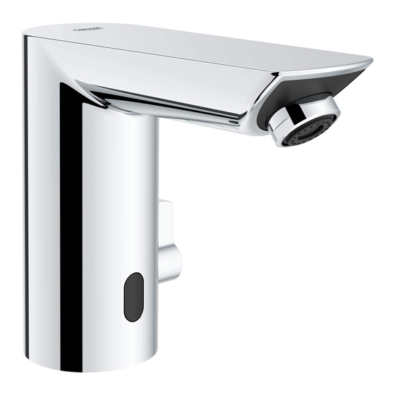
- Page 1 BAU COSMOPOLITAN E DESIGN + ENGINEERING GROHE GERMANY 99.1588.031/ÄM 248928/10.20 www.grohe.com 36 466 36 467 36 469 36 468 2 - 5 6 - 11 12 - 21 22 - 24...
- Page 2 Flush piping system prior and after To be installed according to local codes and installation of fitting thoroughly! regulations. Bien rincer les canalisations avant et A installer conformément aux prescriptions et après l’installation! réglementations locales. ¡Purgar a fondo el sistema de tuberías A ser instalado conforme a códigos y antes y después de la instalación! reglamentos locales.
- Page 3 36 466 *19 017 13mm 1. Clean surface of sink. 2. Install o-ring. In case of deck plate (36 466) install putty plate (additional sealant is recommended) and deck plate, as shown. 3. Insert hoses, cable and faucet through sink opening. 4.
- Page 4 18mm Install inlet adapter to the angle stop. Installer l'adaptateur d'arrivée d'eau sur le robinet d'angle. Instalar el adaptador de admisión en el ángulo de parada. 16mm 18mm Connect hoses to the adapter. Hot water left, cold water right. Raccorder les flexibles sur l'adaptateur. Eau chaude à gauche, eau froide à droite. Conectar las mangueras al adaptador.
- Page 5 36 466 1. Remove mounting set of 2. Install pop-up waste with mounting set 3. Open hot and cold water supply and check pop-up waste. and tighten nut. connections are watertight. 1. Retirer l'ensemble pour 2. Installer le clapet de vidage avec 3.
- Page 6 36 466 / 36 467 / 36 468 36 466 / 36 467 / 36 468 1. Mount wall holder. 2. Insert battery and close cover. Check the right position of battery and cover, as shown. 3. Connect battery box with plug. Check the right position of plug, as shown. 4.
- Page 7 Programs / Programmes / Programa General function: The sensor system is adjusted so that water flow is initiated when the hands approach the vicinity of the spout. Change hot and cold water (not for 36 468) by turning the lever. 7 different programs can be selected for this fitting.
- Page 8 Programs / Programmes / Programa Activating cleaning mode • Only possible when temporary shutoff is activated, overview program table, see page 10 and 11. 1. Hold finger against the lower area of the sensor system. Indicator lamp signals: █████████████████████ ██ ██ ██ ██ ██ 2.
- Page 9 Programs / Programmes / Programa Signaling the remaining battery capacity (also possible for 36 469 - always complete capacity) and performing continuous operation for thermal disinfection (factory setting 4 min). 1. Turn mixer lever to the hot water end stop (if you have no lever you can start immediately). 2.
- Page 10 Programs / Programmes / Programa The remaining battery capacity is signalled by Take hands out of the detection zone of the sensor the number of flashing signals: system. Thermal disinfection starts once the Remaining battery capacity > 60% remaining capacity has been signalled. ██...
- Page 11 Programs / Programmes / Programa 3min 10sec Activating setting mode Disconnect the power supply to the electronics and reconnect after 10 s. Setting mode is automatically terminated after 3 minutes. Activer le mode Réglage Couper l’alimentation électrique du système électronique et la remettre 10 s. Le mode Réglage s’arrête automatiquement au bout de 3 minutes.
- Page 12 Programs / Programmes / Programa 6sec 4. Remove finger from the sensor system after the desired sequence of flashing signals. The program is adopted as the new setting. The corresponding flashing signals are displayed again. Setting can be readjusted within the next 6 s if necessary. Setting mode is automatically terminated after 3 minutes. Programme (1 = factory setting) Temporary shutoff* Active...
- Page 13 If maintenance is required, see Fault/Cause/Remedy (page 22). Si la maintenance est nécessaire, voir Pannes/Causes/Remèdes (page 23). Si el mantenimiento es necesaria, consulte Fallo/Causa/Remedio (page 24). 2,5mm Close hot and cold water supply and disconnect the power supply. 1. Remove set screw and detach mixer lever. 2.
- Page 14 1. Grease o-rings and mount mixer spindle in body. Check the right position of mixer spindle, as shown. 2. Mount nut into mixer spindle. 3. Mount faucet body by pushing downwards and screw in screw. Observe the right position of plug. 1.
- Page 15 2,5mm 1. Mount adapter and screw in screw. 2. Mount mixer lever and screw in set screw. Check the right position of mixer lever, as shown. Connect power supply and open hot and cold water supply. 1. Monter l'adaptateur et visser la vis. 2.
- Page 16 Close hot and cold water supply. 1. Remove battery box from wall holder and disconnect power supply. 2. Open cover. Close hot and cold water supply and disconnect power supply. Couper l'alimentation en eau chaude et froide. 1. Retirer le boîtier de la batterie du support mural et débrancher l'alimentation électrique. 2.
- Page 17 If maintenance is useful, see Fault/Cause/Remedy (page 22). Si la maintenance est utile, voir Pannes/Causes/Remèdes (page 23). Si el mantenimiento es útil, consulte Fallo/Causa/Remedio (page 24). Close hot and cold water supply and disconnect power supply. Remove flow control. Inspect and clean all components and replace if necessary. To replace remove flow control, screw and adapter and grease o-rings of the new adapter.
- Page 18 If maintenance is useful, see Fault/Cause/Remedy (page 22). Si la maintenance est utile, voir Pannes/Causes/Remèdes (page 23). Si el mantenimiento es útil, consulte Fallo/Causa/Remedio (page 24). 16mm 18mm Close hot and cold water supply and disconnect power supply. Remove inlet adapter. Inspect and clean all components and replace if necessary. Assemble in reverse order.
- Page 19 If maintenance is useful, see Fault/Cause/Remedy (page 22). Si la maintenance est utile, voir Pannes/Causes/Remèdes (page 23). Si el mantenimiento es útil, consulte Fallo/Causa/Remedio (page 24). 2,5mm Only if you have a new solenoid valve! Close hot and cold water supply and disconnect power supply. 1.
- Page 20 1. Remove wire clip. 2. Disconnect plug-in connectors. 3. Disconnect solenoid valve by rocking slightly and pulling upwards. 1. Retirer l'agrafe de sûreté. 2. Débrancher les fiches de raccordement. 3. Débrancher l'électrovanne en la faisant légèrement osciller et en la tirant vers le haut. 1.
- Page 21 1. Mount solenoid valve by pushing downwards. 2. Connect plug-in connectors. Check the right position of the plug, as shown. 1. Monter l'électrovanne en la poussant vers le bas. 2. Brancher les fiches de raccordement. Vérifier la position de la fiche, conformément à l'illustration. 1.
- Page 22 1. Mount faucet body by pushing downwards. Make sure sensor is facing forward and plug remain free from residual water. Check the right position of the plug, as shown. 2. Screw in screw. 3. Mount adapter and screw in screw. 4.
-
Page 23: Safety Notes
Electrical test data • Software class Safety notes • Contamination class • Rated surge voltage 2500 V Prevent danger resulting from damaged voltage supply cables. • Temperature of ball impact test 100 °C If damaged, the voltage supply cable must be replaced by the manufacturer or his customer service The test for electromagnetic compatibility (interference department or an equally qualified person. -
Page 24: Consignes De Sécurité
Données d’essai électriques • Classe de logiciel • Degré de salissure Consignes de sécurité • Tension de choc de référence 2 500 V Éviter les dangers entraînés par une tension • Température de l’essai de dureté à la bille 100 °C d’alimentation endommagée. -
Page 25: Información De Seguridad
Datos de comprobación eléctrica • Clase de software • Clase de contaminación Información de seguridad • Sobretensión transitoria 2500 V Evitar peligros derivados del uso de cables de • Temperatura del ensayo de dureza 100 °C alimentación de tensión dañados. En caso de daños debe hacerse que el fabricante o su servicio de La comprobación de la compatibilidad electromagnética postventa o una persona cualificada... - Page 28 +49 571 39 89 333 +33 1 49 97 29 00 +31(0) 88-0030700 +90 216 441 23 70 service.de@grohe.com sav-fr@grohe.com https://www.grohe.nl/nl_nl/ service.turkey@grohe.com onze-service/contact.html +43 1 6 80 60 +358 (09)42451390 +380 (44) 5375273 info-at@grohe.com grohe@grohe.fi +64 09 573 0490 info-ua@grohe.com sales@robertson.co.nz...
Need help?
Do you have a question about the BAU COSMOPOLITAN E 36 466 and is the answer not in the manual?
Questions and answers