Table of Contents
Advertisement
Quick Links
Advertisement
Chapters
Table of Contents
Troubleshooting

Subscribe to Our Youtube Channel
Related Manuals for Bruker CryoProbe


Summary of Contents for Bruker CryoProbe
- Page 1 CryoProbe System User Manual Version 001 BRUKER...
- Page 2 The information in this manual may be altered without notice. BRUKER accepts no responsibility for actions taken as a result of use of this manual. BRUKER accepts no liability for any mis- takes contained in the manual, leading to coincidental damage, whether during installation or operation of the instrument.
-
Page 3: Table Of Contents
Terms and symbols .............. 7 Disclaimer ................8 Emergency ................8 Personnel safety ..............9 Safety of CryoProbe equipment ......... 11 First aid ................11 Introduction ............13 How to use this manual ............. 13 CryoProbe System overview ..........13 Conventions .............. - Page 4 Monitoring and Maintenance ....... 63 Displays & Diagnostics ............63 CryoTool interface ............63 request ........63 Warm-up needed soon CryoProbe insulation indicator ........64 Periodic checks ..............64 Log-book ..............64 Logfile ................66 Replacement of the He steel-cylinder ......66 Software update ..............
-
Page 5: Cool-Down
Cold operation problems ............ 77 flashes ..............77 Emergency warm-up ............. 77 CryoProbe temperature unstable ........78 Condensed water or ice on the CryoProbe ....78 Sample temperature problems ........79 Unusual sounds ............79 Mains power interrupt ........... 79 VT gas interrupt ............ - Page 6 Contents Figures ............... 103 Tables ..............105 6 (107) BRUKER CryoProbe User Manual...
-
Page 7: Safety
Safety 1000000 Read these safety instructions carefully and make them accessible to everybody working with the CryoProbe System. A CryoProbe can be operated easily and safely provided the correct procedures are obeyed and certain precautions ob- served. Terms and symbols WARNING: Disregard of this may lead to personal injury. -
Page 8: Disclaimer
MERGENCY down the systems for cryogenic cooling, vacuum, sensors, and helium gas com- pression. All valves are reset to their default positions. The CryoPreamps inside the CryoProbe, however, are not affected by an E because they MERGENCY are supplied from the HPPR. If the system is kept O , it will slowly warm up due to thermal conduction. -
Page 9: Personnel Safety
Personnel safety Personnel safety All persons who work with or in the close vicinity of a CryoProbe System must be informed about its safety issues and emergency procedures. WARNING: Do not disconnect any tube or cable from a running CryoProbe Sys- tem unless W light up on the CryoCooling Unit front panel. - Page 10 WARNING: Two people are needed to insert and remove the CryoProbe. When kneeling down at the magnet bore, your body posture is not suited to lift the heavy CryoProbe (~12 kg) on your own. For two people it is very easy. Take care not to injure your back!
-
Page 11: Safety Of Cryoprobe Equipment
Safety of CryoProbe equipment CAUTION: - Do not bend the CryoProbe. Do not hold the CryoProbe at its upper tube, always carry it at its body. - Do not open the CryoProbe. There are no user-serviceable parts inside. A CryoProbe cannot be sealed or reassembled without special equipment. - Page 12 Safety 12 (107) BRUKER CryoProbe User Manual...
-
Page 13: Introduction
- "Contents" on page 3, or - "Frequently asked questions" on page 93“ to locate the answer. Novice users of a CryoProbe System should read "Safety" on page 7. Further information can be found in the manuals listed in "Related documents" on page 89. -
Page 14: Figure 2.1. The Cryoprobe™ System
Introduction Figure 2.1. The CryoProbe™ System CryoPlatform CryoProbe Magnet Default configuration: BH 0410 He Gas cylinder Connenction to He-Gas (to be cylinder incl. Pressure provided reduction valve: Z46261 customer) Transferline (Part of CryoCooling Unit) Room temperature He Gas Water pressure lines & Cables... -
Page 15: System Description
3000000 CryoProbe The CryoProbe™ is an NMR probe with the essential parts of the RF preamplifier integrated. Both the NMR coil assembly and the CryoPreamp are cooled by cryo- genic helium gas (He) to achieve an extremely efficient operation of the NMR coil assembly and to significantly reduce thermal noise. -
Page 16: Sample Temperature Control
Differences to a conventional probe 3.1.3 Although the CryoProbe is in a way a regular high-resolution NMR probe, many of its systems are unique and have not been used in an NMR system before. All us- ers of a CryoProbe System must be aware of its differences to a conventional probe to ensure appropriate use and maximum performance. -
Page 17: Cryoplatform
CryoPlatform Connections There are more connectors on the CryoProbe than on a conventional probe due to the built-in preamplifiers and the necessary control circuits (see Figure 3.1.). Sample handling, tuning, shimming There are no differences to a conventional probe with regard to sample handling, sample lift, and sample spinning. -
Page 18: Mounting Hardware
A special fixture must be mounted to the lower RT flange of the magnet bore to carry the weight of the CryoProbe. The Mounting Hardware is attached to the magnet flange with an interface plate which replaces the lower shim system at-... -
Page 19: Cryocooling Unit
CryoPlatform tachment ring. When not used for CryoProbe mounting, this plate does not inter- fere with conventional probes. CryoCooling Unit 3.2.2 The most prominent part of the CryoPlatform is the CryoCooling Unit. Inside, a so- called ‘Coldhead’ expands compressed He and thereby cools it to cryogenic tem- peratures. -
Page 20: Figure 3.4. Status Display By The Control Buttons
Warming up without active heating active heating CryoProbe After pressing , any sensor cable can be removed from the CryoProbe UNPLUG during ~1 min without causing an error. reset RROR may light up in any of the above situations (Figure 3.4.) in addition to the RROR lights displayed. -
Page 21: He Compressor
CryoPlatform if the system is already cold or cooling down. If the CryoProbe System COOL DOWN is warm or warming up, press to reset an E . In case of an E WARM UP RROR RROR please consult also the chapter "Troubleshooting" on page 71. -
Page 22: Cryo-Compatible Preamplifier Assembly 'Hppr Crp
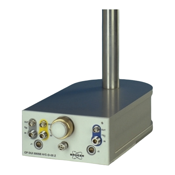
65 dB(A) 2 m distant Cryo-compatible preamplifier assembly ‘HPPR CRP’ Although a CryoProbe has its own set of cold preamplifiers built-in, some HPPR functions such as RF filters in the transmission path, probe tuning, and selection of the received signal must be handled externally by a modified HPPR CRP as- sembly (Figure 3.5.). -
Page 23: Water Chiller (Optional)
(w × d × h in mm) Dimensions main cabinet (indoors) 690 × 920 × 1490 1895 × 470 × 832 radiator (outdoors) Weight main cabinet (indoors) (120 kg empty) 250 kg radiator (outdoors) (94 kg empty) 120 kg CryoProbe User Manual BRUKER 23 (107) -
Page 24: Principle Of Operation
With the displacer at the top of the cylinder, the inlet valve closes and the out- let valve opens to the low pressure reservoir. Gas escapes and the pressure decreases, causing a drop in the gas temperature. The temperature decrease 24 (107) BRUKER CryoProbe User Manual... -
Page 25: Figure 3.6. Gifford-Mcmahon Cycle Refrigerator
2, below, to volume 1, above the dis- placer. As it flows through the regenerator, the fluid is heated by the matrix to near ambient temperature. This process cools the matrix ready for the gas en- tering in the next cycle. CryoProbe User Manual BRUKER 25 (107) -
Page 26: Software
Software The CryoController can be interfaced to a computer running Windows™ 95/NT4 or later. Monitoring software is delivered with the CryoProbe System. Further- more, the XWIN-NMR AU programs crpon, crpoff, crpwobb, crp2hon, and crp1hxon are needed. They are part of XWIN-NMR 2.6 and later. For XWIN- NMR 2.0 or later, an add-on package is available from ftp.bruker.de: /pub/nmr/... -
Page 27: Standard Procedures
See "Cleaning the sample cavity" on page 67 for further information. - probe tube and its joint to the body Do not hold the CryoProbe at its tube. Support and carry the CryoProbe only at its body. Do not bend the tube. -
Page 28: Mounting
Figure 4.2. Never hold a CryoProbe at its tube! CAUTION: Do not heat or cool the CryoProbe housing from the outside (e.g. do not try to speed up the evacuation process by heating the CryoProbe with a heat gun). Mounting Insertion and removal of the CryoProbe can be easily accomplished by the spec- trometer operator with the help of a second person. -
Page 29: Figure 4.3. Preparing The Mounting Hardware
Mounting Figure 4.3. Preparing the Mounting Hardware Check the indicator in the upper right corner of the CryoProbe front. It must not stick out but flush with the front plate. If it sticks out, a problem with the vacuum insulation may have occurred - contact B... - Page 30 IMPORTANT: While sliding it carefully into the magnet, prevent bend- ing of the CryoProbe tube by keeping it close to the rails - but do not press it against them. Do not use any extra force to push it up, it should slide without resistance.
-
Page 31: Figure 4.4. Sliding The Cryoprobe Into The Magnet
Check the orientation of the CryoProbe in the magnet: Its front must be able to meet the He Transferline. IMPORTANT: If cranked pillar braces are present in the magnet stand, the CryoProbe must be centered in their gap at all times (see Figure 4.5.). CryoProbe User Manual... -
Page 32: Figure 4.5. Cryoprobe And Optional Cranked Pillar Braces
(Figure 4.6.). m.13 Turn the other four screws on the support plate in an alternate fashion such that they support the CryoProbe gently. Take care not to tilt its body by forcing one screw more that the other screws. m.14 Lift the magnet. -
Page 33: Sample Spinning Test
Insert a typical sample into the magnet and check if it can be spun. Remove the sample after the test. IMPORTANT: No sample must be in the magnet during the CryoProbe cool- down. Insert samples only if the C button on the CryoCooling Unit is on or at least flashing. -
Page 34: Joining The Cryocoupler
Check the four o-rings on the He Transferline CryoCoupler (Figure 4.7.): are they in place, clean and undamaged? If not replace with the o-rings found in the spare parts box delivered with each CryoProbe System. The o-rings are of type viton and size 7.1 by 1.6 mm. -
Page 35: Figure 4.8. Inserting The Cryocoupler
He Transferline, you will feel where the rotational alignment is just right. Slide the CryoCoupler into the CryoProbe. It should fit smoothly with- out any significant movement of the suspended magnet. CAUTION: If the CryoCoupler gets stuck, do not force it into position. -
Page 36: Connecting
Standard procedures Use the special open-end titanium wrench to fix the CryoCoupler gen- tly to the CryoProbe. Take care not to damage any connectors on the CryoProbe front. Hold the He Transferline end with your other hand to take up the torque applied. -
Page 37: Figure 4.9. Connecting Vt Sensor Cable And Vt Hose (Bottom View)
CryoProbe front VT sensor cable Mount the Vacuum Adapter to the CryoProbe bottom such that it points to the front. Connect the vacuum tube. Push in the actuator screw of the Vacuum Adapter (black handle) in as far as it will go (Figure 4.10.). -
Page 38: Figure 4.10. Open The Cryoprobe Vacuum Plug
Standard procedures Figure 4.10. Open the CryoProbe vacuum plug Draw out the CryoProbe’s actuator screw by at least 5 cm (2 inch) until a stop is reached, thereby taking the vacuum plug out of the Cryo- Probe. NOTE: The vacuum system will be activated later. -
Page 39: Power-On
Table 4.4. Power-on step action All units of the CryoProbe System must be set up correctly. Start the cooling water supply to the He Compressor (water-cooled He Compressor only). The He steel-cylinder main valve must be open and the primary pres- sure gauge on the He steel-cylinder should read 40-200 bar. -
Page 40: Vt Setup
CryoProbe. Both N gas and dry air can be used as VT gases. For a CryoProbe, there is no difference between them with respect to shimming or RF performance. CAUTION: Do not initiate a cool-down if no regulated VT gas flows. Do not insert a sample if the CryoProbe is not at its operating temperature or if the tem- perature in its sample cavity does not stabilize at the desired value. - Page 41 VT setup step action Connect the VT gas inlet of the CryoProbe either directly to the VT unit or to a BCU05 gas cooler but do not switch the BCU05 O yet. CAUTION: When cold operation has been started, the VT gas supply must not be interrupted before the CryoProbe has been warmed-up again.
-
Page 42: Sample Safety Option
Cool-down NOTE: If any detectable malfunction appears, a cool-down will be automatically stopped and the CryoProbe System is automatically warmed-up to ambient tem- perature. CAUTION: Do not move a cryogenically cold device. Do not try to fix a leak on a cold part because cracking of frozen o-rings, valves etc. - Page 43 Lock-in" on page 48. c.12 When C is continuously on, the final conditions are stable. WARNING: Do not disconnect any tube or cable from a running CryoProbe Sys- tem unless lights up on the CryoCooling Unit front panel. Pressurized UNPLUG cryogenic helium gas is circulated between CryoProbe, CryoCooling Unit, and He Compressor.
-
Page 44: Hppr Crp Configuration
X-BB31P_2HS, whereas the HPPR 15N CRP module is wired to ‘UB’ and shows up as X-BB19F_2HS. The conventional HPPR X-BB module is not connected when a CryoProbe TXI is used, neither to the ribbon cables nor to the RF lines that lead from the left side to the cover module (Figure 4.12.). -
Page 45: Low Temperature Limit In Sample Cavity
Task: Observe C on a CryoProbe TXI in the presence of a high-sensitivity lock. Setup: In a CryoProbe TXI, the 13C channel is intended for decoupling only and features no CryoPreamp. However, C detection is possible when using the warm HPPR 13C CRP preamp module. Send its output to the FT receiver but feed the output of the build-in cold H preamp into the lock receiver. -
Page 46: Determine Lowest Sample Cavity Temperature
Leave the VT heater off. INGS Select the desired VT gas flow rate. NOTE: A high VT gas flow is generally to be preferred for a CryoProbe as long as it does not lift the sample. See the minimum flow rate on the ‘L ’... -
Page 47: Tuning And Matching
NOTE: The VT hose must not be covered with ice at the point where it enters the CryoProbe body. If the CryoProbe body is cooled by the VT gas and becomes wet with condensed water, the hose must be extend- ed. -
Page 48: Shimming And Lock-In
In contrast to the 1H and X channels, the lock channel of a CryoProbe may need as much (or even more) RF power as a conventional probe. If in doubt about the lock power, per-... -
Page 49: Warm-Up
WARNING: Do not attempt to insert or remove the heavy CryoProbe (~12 kg) at the magnet without the help of a second person. Because your body’s posture is... -
Page 50: Remove The Cryoprobe
Standard procedures It is impossible to remove the CryoProbe from the magnet while it is connected to the He Transferline. There are geometrical restrictions and the danger of bending the CryoProbe tube with the large lever of the He Transferline. -
Page 51: Figure 4.13. Removing The Vacuum Connector From The Cryoprobe
(cf. "Mounting" on page 28 and Figure 4.8.). Support the He transferline at its original height while drawing the CryoCoupler carefully out of the CryoProbe. Make sure to exert no torque on the CryoProbe body. Do not use large forces, the suspended magnet must not move. r.10 Check if all 4 o-rings on the He Transferline CryoCoupler are still in place (Figure 4.7.). -
Page 52: Power-Down
CAUTION: Never carry a CryoProbe at its tube, hold it at its body only. Cover the sample cavity with the Protection Cap to prevent water con- densation, dust contamination, and intrusion of foreign objects. Put the CryoProbe into its flight case for safe storage in a dry and clean place. -
Page 53: Spectrometer Operation With Conventional Probes
IMPORTANT: The He compressor and the Flexlines must remain pressurized to about 15 bar at any time to prevent contamination. When the CryoProbe System is shut down, it automatically vents some parts while others remain pressurized. Its seals are designed to hold the pressure over an extended period. Do not try to release this pressure by any means! Safety-valves will prevent damage if excess pressure builds up accidentally. - Page 54 Standard procedures 54 (107) BRUKER CryoProbe User Manual...
-
Page 55: Recommended Nmr Parameters
Sample temperature control Although the CryoProbe has an excellent thermal insulation between the sample space and the cold RF coils, a small thermal radiation is constantly cooling the sample. A sufficient VT gas flow is crucial to avoid temperature gradients in the sample. -
Page 56: Measurements Above Tvt Gas+ 3°C
Both N gas and dry air can be used as VT gases. For a CryoProbe, there is no difference between them with respect to shimming or RF performance. For measurements at low sample temperatures, a BCU05 gas cooler is required. -
Page 57: Measurements Below Tvt Gas+ 3°C
Never use a liquid nitrogen evaporator to provide cold VT gas. CAUTION: Use a special VT adapter or a hose connection of sufficient length such that, at the point where the hose enters the CryoProbe, there is no freezing or condensation. Tuning the regulation loop 5.3.3... -
Page 58: Preamplifier
Keep parameter sets for conventional and CryoProbes well separated. Peak RF power 5.5.1 Due to the high efficiency of the CryoProbe, the maximum RF power may be significantly less than those on conventional probes. The highest power lev- els available in A... -
Page 59: Simultaneous Hard Pulses
Average RF power 5.5.3 CAUTION: The decoupling power required by a CryoProbe for a given RF field strength is much smaller than in a conventional probe. In cases where the average RF power exceeds the cooling capacity of the sys- tem, the NMR coil assembly cannot keep its nominal operating temperature. -
Page 60: Receiver Setting
For small receiver gain values, i.e. rg < ~256, the signal-to-noise tends to de- crease in proportion to rg. If the CryoProbe is always used with samples that yield a strong NMR signal like an H... -
Page 61: Solvent Suppression
(other shims are usually of little effect). When changing the VT gas flow rate, the procedure must be repeated. Solvent suppression There is no preferred solvent suppression technique for use with a CryoProbe. All standard methods like presaturation, W , and Excitation Sculpting can be ATERGATE used as usual. - Page 62 ∆z you have to change your z-shim to have the lock back to the top gridline. Add some dummy scans to your experiment and add ∆z to the z-shim. Run your experiment. Once the experiment is finished, subtract ∆z from the z-shim. 62 (107) BRUKER CryoProbe User Manual...
-
Page 63: Monitoring And Maintenance
Monitoring and Maintenance 6000000 In this chapter, the various indicators for the CryoProbe System status are intro- duced. The system should be monitored continuously in order to preserve perfor- mance, identify emerging problems early, prevent serious damage, and to trace faults back to their origins. -
Page 64: Cryoprobe Insulation Indicator
In the upper right corner of the front plate, there is a little hole with an indicator in- side. This indicator must be flush with the CryoProbe front at room temperature. If the indicator sticks out, a problem with the CryoProbe’s insulation may have oc-... -
Page 65: Operating Log For Cryocooling Unit And He Compressor
He Compressor front b as displayed on the CryoCooling Unit back He steel-cylinder primary pressure [bar], must be > 30 bar Page d e.g. ‘cool-down’, ‘cold operation’, ‘start HSQC’ .... CryoProbe User Manual BRUKER 65 (107) -
Page 66: Logfile
However, since He is mostly consumed when a cool-down is initiated, a cold CryoProbe System can run a long time even with an almost empty He steel-cylinder as long as the He pressure is ≥ 30 bar. -
Page 67: Software Update
Cleaning the sample cavity 6.4.1 The CryoProbe sample cavity is extremely fragile. Even a tiny scratch inside can spoil the CryoProbe performance and entail a major repair action. Preventive cleaning is not recommended - clean only in case of problems. -
Page 68: Panels And Housings
Monitoring and Maintenance Put the CryoProbe upside down onto the edge of a level surface, e.g. a table, such that it cannot fall down. Its tube must point down but without touching anything. Protect your eyes with goggles. Connect the VT gas to its regular input at the CryoProbe bottom and select a flow rate ≥... - Page 69 Exchange of Adsorber in He Compressor Needed every 20 000 h. Since a specialist must visit each 10 000 h anyhow for the Coldhead exchange, Adsorber and Coldhead exchange can be combined. CryoProbe User Manual BRUKER 69 (107)
- Page 70 Monitoring and Maintenance 70 (107) BRUKER CryoProbe User Manual...
-
Page 71: Troubleshooting
Probe can easily be damaged in an attempt to open it. There are no repair actions that could be performed by the user. For troubleshooting, there is usually no advantage in taking the CryoProbe out of the magnet except for those cases where it is obviously necessary, e.g. to remove dirt from the sample cavity. -
Page 72: Consequences Of An E
CryoCooler immediate stop; all valves go to safe none default CryoController default positions; He dumped from decides CryoCooling Unit and CryoProbe; stable He supply valve between He Hose and Cryo- none closed CryoController Cooling Unit closed; stable decides Vacuum sys- immediate stop;... -
Page 73: First Diagnosis
To reset an E on the CryoCooling Unit front panel, press if the RROR COOL DOWN system is already cold or cooling down. If the CryoProbe System is warm or warming up, press ’. WARM UP He Compressor See the schematics in the He Compressor operation manual for the location of the fuses. -
Page 74: General Failure
When the CryoProbe had been removed and was mounted again Is the CryoProbe at the correct position inside the shim system, i.e. is there a gap of ~0.5 mm between the CryoProbe body and the shim system bottom plate? Is... -
Page 75: Indicator On Cryoprobe Sticks Out
38 mm. Insert the CryoProbe. Measure the new gap and subtract the height of the ring. The missing length be- tween CryoProbe and spinner stator results. If it is in the order of 1 mm or more, call your B... -
Page 76: Insufficient Vacuum
Insufficient vacuum pumps, or if the vacuum pumps sound strange, - the vacuum bellows may not be properly connected at the CryoProbe or at the Transferline Support, - the Vacuum Adapter may not be locked tightly to the CryoProbe bottom... -
Page 77: Cool-Down Doesn't Reach Cold State
Note that a cool-down attempt will be refused until all parts have reached ambient temperature unless the system has been in the passive emergency warm-up only for a very short period of time. CryoProbe User Manual BRUKER 77 (107) -
Page 78: Cryoprobe Temperature Unstable
CryoProbe System will be automatically warmed up by the Cryo- Controller. Since on-site repair of a CryoProbe is impossible, it must be sent to . Send also the latest logfile (see "Logfile" on page 73) via e-mail be-... -
Page 79: Sample Temperature Problems
CryoProbe is cold. The sample may cool down to cryogenic temperatures, poten- tially breaking the sample tube or damaging the substance under investigation. VT gas must flow through the CryoProbe at all times even if no sample is present to avoid water condensation. - Page 80 When the user returns to the NMR lab, the CryoProbe System will be al- ready on its way to re-establish measuring conditions. The NMR acquisition, how- ever, is controlled by the CCU in the spectrometer cabinet and will not be re- initiated automatically for safety reasons.
-
Page 81: Vt Gas Interrupt
If a closed-cycle water chiller is used: determine the cause of leakage before refill- ing the chiller. If a water leak cannot be sealed during operation, the CryoProbe must be warmed If the cooling water supply is interrupted or drops such that the heat cannot be removed anymore, the He Compressor and the CryoCooling Unit will stop after a while and perform a passive emergency warm-up. -
Page 82: Shot' Noise
CryoProbe properly connected at the back of the HPPR CRP or HPPR/2 cover? - All RF filters needed for the CryoProbe are already built-in. Do not use extra fil- ters. If it looks as if extra RF filters would be needed to improve the situation,... -
Page 83: Tuning/Matching Not Ok
Adapter and the blue Tuning Tool to adjust the tuning or matching. Execute crpwobb and wobb: a tunable dip must appear on the display for each channel. This indicates if most of the signal routing to and from the CryoProbe and most of the CryoProbe itself are working. -
Page 84: Spurious Signals
Spurious signals 7.7.3 All RF filters needed for the CryoProbe are already built-in. Do not use extra fil- ters. If it looks as if extra RF filters would be needed to improve the situation, con- tact B... -
Page 85: Accidental Misoperation
Accidental misoperation magnet pillar braces are mounted, the CryoProbe body must fit their gap (see Figure 4.5.). If the problem persists, contact B RUKER Accidental misoperation Too much RF power Check if the probe can still be wobbled. CAUTION: A CryoProbe must not be tuned or matched when warm. - Page 86 Troubleshooting 86 (107) BRUKER CryoProbe User Manual...
-
Page 87: Bruker Contact
RUKER 8000000 Submit your inquiries about CryoProbe sales and service to your local B RUKER representation. Use the following address only if they cannot help you. CryoProbe information CryoProbe information head offices: Instruments, Inc. RUKER RUKER Probe Department 44 Manning Road... -
Page 88: Bruker Contact
- CryoController Firmware and CryoTool version (see the Cryo Main window on the CryoProbe System PC, e.g. Firmware: 991112, Cryo Main (Sep 06 ; if the CryoProbe interface is not active, click Start - Programs - CryoTool 1999) - CryoTool and select COM1),... -
Page 89: Related Documents
CryoProbe data sheets RF power limits, sample temperature range etc. specific for the actual CryoProbe. CryoProbe System Installation Manual (P/N Z31555) Installation and initial setup of a new or relocated CryoProbe System and its op- tional devices. He Compressor technical manual The operation manual is delivered with the He Compressor. -
Page 90: Figure A.1. When To Use Which Cryoprobe Document
Related documents Figure A.1. When to use which CryoProbe document Supporting Operation document Site Planning site planning Questionnaire Site Planning Guide Site Preparation site preparation Manual relocate initial setup Installation of CryoPlatform CryoPlatform Manual mount conventional probe mount remove User... -
Page 91: Conversion Of Metric Units
1 btu ≈ 0.293 Wh 1 mT ≡=10 Gauss 1 Gauss ≡=0.1 mT °C to °F: °F to °C: × ⁄ – °F °C °C °F Table B.1. Conversion between °C and °F temperature scales °C °F CryoProbe User Manual BRUKER 91 (107) -
Page 92: Conversion Of Metric Units
Conversion of metric units 92 (107) BRUKER CryoProbe User Manual... -
Page 93: Frequently Asked Questions
Probe Mounting Hardware. Is a VT gas cooler recommended? The CryoProbe can be operated with and without a VT gas cooler. Currently, only the BCU05 is approved. It is needed for measurements below room temperature and slightly above room temperature (i.e. up to 3 - 5°C higher). A nitrogen evapo- rator must not be used. -
Page 94: Nmr Operation
Which experimental parameters do I have to be careful with to avoid damage to the CryoProbe? Maximum RF power. In general, a CryoProbe requires significantly less RF power to achieve the same pulse lengths as conventional probes. Does the CryoProbe change its characteristics during long... -
Page 95: Basic Aspects
All the common probe functions needed for RF transmission, tuning, gradient pulses, and VT gas duct are built into the CryoProbe, while the sample lift and spinning are provided as usual by the shim upper part. - Page 96 Frequently asked questions 96 (107) BRUKER CryoProbe User Manual...
-
Page 97: Glossary
CryoPlatform. CryoCoupler Standardized interface between the He Transferline from the CryoCooling Unit and the CryoProbe that connects both forward and backward streams of cold He at once. CryoPlatform All parts needed for operating a CryoProbe with a spectrometer, i.e. CryoProbe Mounting Hardware, CryoCooling Unit, He Compressor, He Transferline, Trans- ferline Support, VT Interface Box, and optional magnet stand modifications. - Page 98 Gaseous helium of high purity, used for cryogenic cooling of the CryoProbe. He Compressor Warm He from the CryoProbe is routed through the CryoCooling Unit to the He Compressor. The compressed He is sent back to the CryoCooling Unit, circulating in a closed loop.
- Page 99 Glossary He steel-cylinder Standard helium gas steel-cylinder (50 ) for the initial fill of the CryoProbe System and for flushing the closed-loop He cycle before each cool-down. He Transferline Isolated tube through which the cold He from the CryoCooling Unit flows to the CryoProbe.
- Page 100 CryoProbe’s Vacuum Plug in and out. Vacuum Plug A small metal plug with an o-ring and an inner thread that closes the CryoProbe vacuum chamber against moisture and dirt. Vacuum bellows Flexible metal vacuum bellows that connects the CryoProbe isolation to the vacu- um system inside the CryoCooling Unit.
- Page 101 Glossary the ‘pneumatic gas’ used for operating valves inside the CryoCooling Unit or with the helium gas circulated through the CryoProbe for cryogenic cooling. VT Interface Box A small box with two cables which interfaces heater and temperature sensor be- tween CryoProbe and VT unit.
- Page 102 Glossary 102 (107) BRUKER CryoProbe User Manual...
- Page 103 Figure 4.10. Open the CryoProbe vacuum plug ........38 Figure 4.11. Switching on the He Compressor ........40 Figure 4.12. Internal wiring of a HPPR CRP for a TXI CryoProbe ... 44 Figure 4.13. Removing the vacuum connector from the CryoProbe ..51 Recommended NMR parameters Figure 5.1.
- Page 104 Figures Bruker contact Related documents ..........89 Figure A.1. When to use which CryoProbe document ......90 Conversion of metric units ........91 Frequently asked questions ........ 93 Glossary ............... 97 104 (107) BRUKER CryoProbe User Manual...
- Page 105 Cool-down ..............42 Table 4.7. Preamplifier selection ............ 45 Table 4.8. Determine lowest sample cavity temperature ....46 Table 4.9. How to wobble the CryoProbe ........47 Table 4.10. Warm-up ................ 49 Table 4.11. Remove the CryoProbe ..........50 Table 4.12.
-
Page 106: C Frequently Asked Questions
Tables C Frequently asked questions D Glossary 106 (107) BRUKER CryoProbe User Manual... - Page 107 Lastpage End of Document CryoProbe User Manual BRUKER 107 (107)
Need help?
Do you have a question about the CryoProbe and is the answer not in the manual?
Questions and answers