Sign In
Upload
Manuals
Brands
Bruker Manuals
Laboratory Equipment
CryoProbe
Bruker CryoProbe Manuals
Manuals and User Guides for Bruker CryoProbe. We have
2
Bruker CryoProbe manuals available for free PDF download: User Manual, Installation Manual
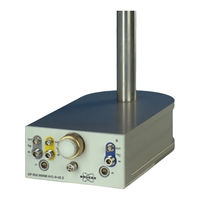
Bruker CryoProbe User Manual (107 pages)
Brand:
Bruker
| Category:
Laboratory Equipment
| Size: 3 MB
Table of Contents
Table of Contents
3
Contents
3
Cool-Down
5
1 Safety
7
Terms and Symbols
7
Figure 1.1. Hot Surface
7
Figure 1.2. High Voltage
7
Figure 1.3. Dangerous Device
7
Figure 1.4. Cold Surface
7
Disclaimer
8
Emergency
8
Figure 1.5. Wear Protective Gloves
8
Figure 1.6. Wear Protective Goggles
8
Figure 1.7. Strong Attraction by Magnet
8
Mergency off
8
Personnel Safety
9
Safety of Cryoprobe Equipment
11
First Aid
11
2 Introduction
13
How to Use this Manual
13
Cryoprobe System Overview
13
Conventions
13
Figure 2.1. the Cryoprobe™ System
14
3 System Description
15
Cryoprobe
15
Figure 3.1. a Cryoprobe
15
Differences to a Conventional Probe
16
Reproducibility
16
Sample Temperature Control
16
Cryoplatform
17
Figure 3.2. a Cryoplatform
18
Mounting Hardware
18
Cryocooling Unit
19
Figure 3.3. Control Indicators on the Cryocooling Unit Front
19
Figure 3.4. Status Display by the Control Buttons
20
Warm-Up Needed Soon
20
He Compressor
21
Cryo-Compatible Preamplifier Assembly 'HPPR CRP
22
Water Chiller (Optional)
23
Figure 3.5. Cryo-Compatible Preamplifier Assembly 'HPPR CRP
23
Principle of Operation
24
Gifford-Mcmahon Cycle Refrigerator
24
Figure 3.6. Gifford-Mcmahon Cycle Refrigerator
25
Software
26
4 Standard Procedures
27
LIMITATIONS - WARNINGS Sheet
27
Handling
27
Figure 4.1. Carry a Cryoprobe Only at Its Body
27
Mounting
28
Figure 4.2. Never Hold a Cryoprobe at Its Tube
28
Mount the Cryoprobe
28
Figure 4.3. Preparing the Mounting Hardware
29
Figure 4.4. Sliding the Cryoprobe into the Magnet
31
Figure 4.5. Cryoprobe and Optional Cranked Pillar Braces
32
Sample Spinning Test
33
Figure 4.6. Final Positioning of the Cryoprobe
33
Joining the Cryocoupler
34
Figure 4.7. O-Rings on the Cryocoupler
34
Join the Cryocoupler
34
Figure 4.8. Inserting the Cryocoupler
35
Connecting
36
Connect the Cryoprobe
36
Figure 4.9. Connecting VT Sensor Cable and VT Hose (Bottom View)
37
Figure 4.10. Open the Cryoprobe Vacuum Plug
38
Power-On
39
VT Setup
40
Figure 4.11. Switching on the He Compressor
40
Sample Safety Option
42
Cool-Down
42
HPPR CRP Configuration
44
Figure 4.12. Internal Wiring of a HPPR CRP for a TXI Cryoprobe
44
Low Temperature Limit in Sample Cavity
45
Preamplifier Selection
45
Determine Lowest Sample Cavity Temperature
46
Tuning and Matching
47
Shimming and Lock-In
48
Warm-Up
49
Removal
49
Remove the Cryoprobe
50
Figure 4.13. Removing the Vacuum Connector from the Cryoprobe
51
Power-Down
52
Spectrometer Operation with Conventional Probes
53
5 Recommended NMR Parameters
55
General
55
Samples and Spinners
55
Sample Temperature Control
55
Measurements above TVT Gas+ 3°C
56
Figure 5.1. the Different Ranges of the Target Temperature
56
Measurements below TVT Gas+ 3°C
57
Tuning the Regulation Loop
57
Wiring
57
Preamplifier
58
Additional RF Filters
58
RF Power Limitations
58
Peak RF Power
58
Simultaneous Hard Pulses
59
Average RF Power
59
Receiver Setting
60
Shimming
60
Gradient Shimming
60
O Samples
60
Solvent Suppression
61
Gradients
61
Pulse Programs
61
Automation
61
6 Monitoring and Maintenance
63
Displays & Diagnostics
63
Cryotool Interface
63
Warm-Up Needed Soon
63
Request
63
Warm-Up
63
Cryoprobe Insulation Indicator
64
Periodic Checks
64
Log-Book
64
Operating Log for Cryocooling Unit and He Compressor
65
Logfile
66
Replacement of the He Steel-Cylinder
66
Replace the He Steel-Cylinder
66
Software Update
67
Cleaning
67
Cleaning the Sample Cavity
67
Panels and Housings
68
Scheduled Maintenance
68
Monitoring and Maintenance
68
7 Troubleshooting
71
Emergency Procedures
71
Emergency off
71
Consequences of an E
72
First Diagnosis
73
Logfile
73
Fuses and Reset Buttons
73
General Failure
74
No Mains
74
Spinning Problems
74
Cryocontroller Failure
75
Indicator on Cryoprobe Sticks out
75
Leak in He Supply
75
Cool-Down Problems
75
COOL down Command Is Ignored
75
He Compressor Does Not Run
76
Insufficient Vacuum
76
Troubleshooting the He Compressor
76
Cool-Down Doesn't Reach Cold State
77
Cold Operation Problems
77
COLD Flashes
77
Emergency Warm-Up
77
Condensed Water or Ice on the Cryoprobe
78
Cryoprobe Temperature Unstable
78
Mains Power Interrupt
79
Sample Temperature Problems
79
Unusual Sounds
79
Cooling Water Leakage
81
He Leakage
81
He Steel-Cylinder Empty
81
Pneumatic Gas Pressure too Low
81
VT Gas Interrupt
81
Shot' Noise
82
RF Problems
82
Lock Problems
83
Tuning/Matching Not OK
83
Spurious Signals
84
Accidental Misoperation
85
8 Bruker Contact
87
Cryoprobe Information
87
Cryoprobe Service
87
Fault Report
87
Bruker Contact
88
Related Documents
89
Figure A.1. When to Use Which Cryoprobe Document
90
Power-Down
90
Conversion between °C and °F Temperature Scales
91
Conversion of Metric Units
91
Conversion of Metric Units
92
Frequently Asked Questions
93
System Configuration
93
NMR Operation
94
Basic Aspects
95
Glossary
97
Figures
103
C Frequently Asked Questions
106
Advertisement
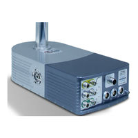
Bruker CryoProbe Installation Manual (93 pages)
Brand:
Bruker
| Category:
Laboratory Equipment
| Size: 3 MB
Table of Contents
Table of Contents
3
Contents
3
1 Safety
7
Terms and Symbols
7
Disclaimer
8
Emergency
8
Personnel Safety
9
Safety of Cryoprobe Equipment
11
First Aid
11
2 Introduction
13
How to Use this Manual
13
Cryoprobe System Overview
13
Conventions
14
Figure 2.1. the Cryoprobe™ System
14
3 Initial Setup
17
Before Delivery
17
Transport
17
Check the Site Preparations
18
Initial Setup
18
Before You Unpack
19
Unpacking
19
Figure 3.1. Cryoprobe Handling
20
Positioning the Units
21
BCU05 Cooling Test (Optional)
22
Spectrometer Modifications
22
Access to the Magnet Bottom
22
Cranked Magnet Pillar Braces (Optional)
23
Blue Spinning Stator
24
Replacing the Shim System (Optional)
24
Attach the Mounting Hardware
25
Handling
27
Mounting
28
Figure 3.4. Preparing the Mounting Hardware
29
Figure 3.5. Sliding the Cryoprobe into the Magnet
31
Figure 3.6. Cryoprobe and Optional Cranked Pillar Braces
32
Sample Spinning Test
33
Figure 3.7. Final Positioning of the Cryoprobe
33
Joining the Cryocoupler
34
Figure 3.8. Unlock the Vaccum Flange Screws
35
Figure 3.9. O-Rings on the Cryocoupler
35
Figure 3.10. Turn the Cryocoupler
36
Figure 3.11. Inserting the Cryocoupler
37
Load Firmware
38
Boot the Cryocontroller
39
Hook up the He Steel-Cylinder
41
Figure 3.12. Attaching the He Hose
42
Interconnect the He Compressor
43
Warning Labels
45
Connecting
46
Figure 3.14. Connecting VT Sensor Cable and VT Hose (Bottom View)
47
Figure 3.15. Open the Cryoprobe Vacuum Plug
48
Power-On
49
VT Setup
50
Figure 3.16. Switching on the He Compressor
50
Initial He Fill
52
Cool-Down
52
Load Additional X WIN - NMR
54
Put HPPR CRP Assembly into Operation
54
How to Proceed
55
4 Customizing the Cryoprobe System
57
Experimental Parameters
57
Lock Power
57
RF Power Levels
57
Safety Attenuators
57
Sample Temperature Control
57
Standard Parameter Sets
57
Receiver Sensitivity
58
Sample Tubes and Spinners
58
Acceptance Tests
58
User Training
58
5 Troubleshooting
59
Fuses and Reset Buttons
59
General Failure
60
No Mains
60
Spinning Problems
60
Cryocontroller Failure
61
Indicator on Cryoprobe Sticks out
61
Leak in He Supply
62
Cool-Down Problems
62
COOL down Command Is Ignored
62
Insufficient Vacuum
62
He Compressor Does Not Run
63
Periodic Hiss Is Missing
65
Cool-Down Doesn't Reach Cold State
66
How to Open the Cryocooling Unit
67
Refill He
67
6 Relocation of a Cryoplatform
69
Relocation
69
Cryoprobe System Storage
69
Disposal
69
Figure 6.1. Releasing the Gas from the Cryocooling Unit
70
Pressure Release
70
Toxic Materials
70
7 Bruker Contact
73
Cryoprobe Information
73
Cryoprobe Service
73
Check Lists
75
Site Preparation Checks
75
Preparations for the Installation Visit
75
User Training
76
Related Documents
79
Figure A.1. When to Use Which Cryoprobe Document
80
Conversion of Metric Units
81
Conversion of Metric Units
82
Glossary
83
Figures
89
Tables
91
Advertisement
Related Products
Bruker Contour GT-K
Bruker CTX
Bruker CounterTop XRF
Bruker 300'154 Ascend DNP
Bruker 300'89 Ascend
Bruker 500'54 Ascend ULH
Bruker 500'89 Ascend Aeon
Bruker 600'54 Ascend ULH
Bruker 700'54 Ascend
Bruker Anton Paar
Bruker Categories
Laboratory Equipment
Measuring Instruments
Industrial Equipment
Security Sensors
Accessories
More Bruker Manuals
Login
Sign In
OR
Sign in with Facebook
Sign in with Google
Upload manual
Upload from disk
Upload from URL