Advertisement
Table of Contents
Q U I C K S T A R T
Carefully unpack box.
1
START HERE
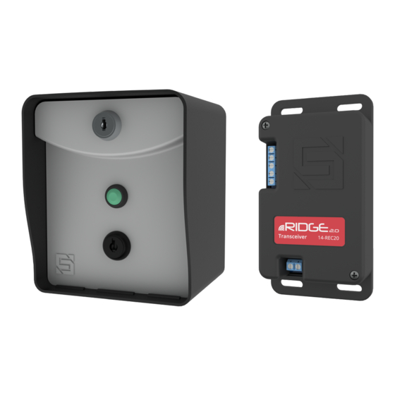
What's what?
Important components labeled
RTE Unit Front Panel
(Front)
G U I D E
Make sure you have all items shown here. (Screwdriver not shown)
2
RTE Unit
Lock
For securing interior
of RTE unit
Exit Button
Triggers gate/door
to open
Key Switch
For enabling and
disabling unit
(Unit is disabled as
shown)
RTE Unit Front Panel
Internal wiring not shown for clarity.
Transceiver Unit
9-V Battery
Key Switch Keys
Reset Button
For pairing RTE unit
with transceiver
9-V Battery
Must be installed
before use
(Back)
Model
Lock Key
Carriage Bolt
Hex Nut
Hole Plug
( 4x )
( 4x )
Connection Terminals
For wiring to compatible
AC/DC power source and
gate operator or door opener
Power LED
Indicates whether or
not unit has power
Relay Status LED
Indicates whether relay is
active or inactive
(Relay is active when lit)
Programming Button
For pairing transceiver
with RTE unit
Programming LED
Indicates status of
pairing process
Transceiver
Shown with cover removed.
Internal wiring not shown for clarity.
1 of 4
14-RTE433
Adhesive
Mounting Pad
Advertisement
Table of Contents

Subscribe to Our Youtube Channel
Related Manuals for Security Brands Ridge RTE 14-RTE433


Summary of Contents for Security Brands Ridge RTE 14-RTE433
- Page 1 1 of 4 Q U I C K S T A R T G U I D E 14-RTE433 Model Carefully unpack box. Make sure you have all items shown here. (Screwdriver not shown) START HERE RTE Unit Transceiver Unit 9-V Battery Key Switch Keys Lock Key...
- Page 2 Terminals vary widely across Terminals vary widely across Power Source Power Source manufacturers and models. manufacturers and models. (Not Included) (Not Included) ALWAYS USE SAFETY DEVICES! © 2021 Security Brands, Inc. All rights reserved. QSG-14RTE433-EN Rev. A (3/2021)
- Page 3 3 of 4 Q U I C K S T A R T G U I D E 14-RTE433 Model Remove transceiver cover; then Remove RTE unit front panel; then hold While pairing, RTE unit will beep momentarily. hold down Programming button on down Reset button on circuit board for Once transceiver LED goes out, pairing is complete.
- Page 4 Q U I C K S T A R T G U I D E 14-RTE433 Model Notes Ridge RTE 14-RTE433 NEED HELP Call (972) 474-6390 Email techsupport@securitybrandsinc.com We are available Mon–Fri / 8am–5pm Central © 2021 Security Brands, Inc. All rights reserved. QSG-14RTE433-EN Rev. A (3/2021)
Need help?
Do you have a question about the Ridge RTE 14-RTE433 and is the answer not in the manual?
Questions and answers