Table of Contents
Advertisement
Quick Links
Advertisement
Table of Contents

Related Manuals for XAC FD150


Summary of Contents for XAC FD150
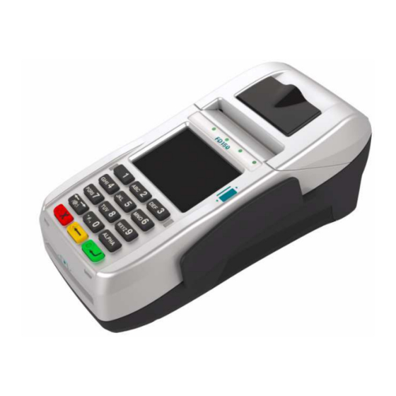
- Page 1 FD150 AYMENT ERMINAL NSTALLATION UIDE...
- Page 2 1. B EFORE TARTING Open the gate behind the device (Figure 1), and find the power input on the right side of the terminal. Connect the plug from the power adapter into the power input (Figure 2). Plug the power adapter into a 120-volt electrical outlet or into a surge suppressor (recommended) after the power cord is connected to the power adapter.
- Page 3 Contactless reader antenna is around the display and PIN pad. It will light up with blue color signal when FD150 is powered on and that means reader is working normally. Put contactless card to approach the antenna of card reader (Figure 13) for reading the card data during transaction.
- Page 4 RIVACY HIELD The privacy shield of the FD150 is shown as figure 18. To install, place the privacy shield over the terminal and hook the top hooks to the device basins beside keypad number 1 and 3. Whilst hooked on, apply pressure to the bottom part of the shield so that it clicks into the bottom hooks shown on figure 19.
- Page 5 See installation instructions for details. Warning: If the device, FD150, is used without the detachable privacy shield, the following criteria needs to be met by the Installed Environment of the PED for complying with the PCI privacy screen design requirement: A.
Need help?
Do you have a question about the FD150 and is the answer not in the manual?
Questions and answers