M&C EC Series Instruction Manual
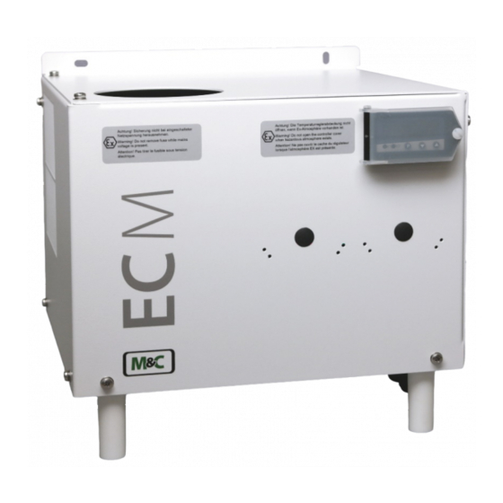
Electric gas cooler
Hide thumbs
Also See for EC Series:
- Instruction manual (44 pages) ,
- Instruction manual (40 pages) ,
- Instruction manual (41 pages)


Need help?
Do you have a question about the EC Series and is the answer not in the manual?
Questions and answers