M&C EC Series Instruction Manual
Electric gas cooler
Hide thumbs
Also See for EC Series:
- Instruction manual (44 pages) ,
- Instruction manual (29 pages) ,
- Instruction manual (40 pages)

Related Manuals for M&C EC Series


Summary of Contents for M&C EC Series
- Page 1 Electric Gas Cooler Series EC ® ECM-ExII EX II 3G ec …. Class I, Div. 2, Groups A/B/C/D, T4 Instruction Manual Doc: M_ECM-EX_EN_ Version 1.02.00...
- Page 2 Dear customer, Thank you for buying our product. In this instruction manual you will find all necessary information about this M&C product. The information in the instruction manual is fast and easy to find, so you can start using your M&C product right after you have read the manual. If you have any question regarding the product or the application, please don’t hesitate to contact M&C or your M&C authorized distributor.
-
Page 3: Table Of Contents
Content General information ......................4 Declaration of conformity ....................4 Safety instructions ......................5 Warranty ..........................6 Warning signs and definitions.................... 6 Information and safety instructions for using the cooler in hazardous areas ....8 Information and safety instructions for using the cooler........... 9 Introduction ........................ -
Page 4: General Information
Head Office M&C TechGroup Germany GmbH Rehhecke 79 40885 Ratingen Germany Telephone: 02102 / 935 - 0 Fax: 02102 / 935 - 111 E - mail: info@mc-techgroup.com www.mc-techgroup.com General information The product described in this manual has been built and tested in our production facility. All M&C products are packed to be shipped safely. -
Page 5: Safety Instructions
Safety instructions Please follow these safety directions and instructions regarding installation, commissioning and operation of the equipment: Read this manual before commissioning and operating the product. Please make sure to follow • all safety instructions. Attention must be paid to the requirements of the Type Examination Certificate (see appendix): •... -
Page 6: Warranty
Warranty In case of a device failure, please contact immediately M&C or your M&C authorized distributor. We have a warranty period of 12 months from the delivery date. The warranty covers only appropriately used products and does not cover the consumable parts. Please find the complete warranty conditions in our terms and conditions. - Page 7 High voltages! Protect yourself and others against damages which might be caused by high voltages. Toxic! Acute toxicity (oral, dermal, inhalation)! Toxic when in contact with skin, swallowed or inhaled. Corrosive! These substances destroy living tissue and equipment upon contact. Do not breathe vapors;...
-
Page 8: Information And Safety Instructions For Using The Cooler In Hazardous Areas
Information and safety instructions for using the cooler in hazardous areas The compressor cooler ECM-ExII is suitable for using in hazardous area of zone 2 (see Ex-certificate). The explosion proof protection for both models is: 230 V / 115 V: II 3 G Ex nA nC IIC T4 Gc (Registration-No.: BVS 16 ATEX E 055 X) 230V / 115V: Class I, Div. -
Page 9: Information And Safety Instructions For Using The Cooler
Information and safety instructions for using the cooler Inhalation hazard possible, if using toxic or asphyxiant gases! Warning Purge cooler with inert gas or air before opening! If the cooler is used for toxic gas or asphyxiant (oxygen-displacing) gas, it needs to be purged with inert gas or air before opening. -
Page 10: Introduction
Introduction The M&C ECM-ExII gas cooler unit is designed to operate whenever there is moisture interference in the sample gas. Lowering the sample gas temperature to a very low and stable dew point prevents condensate built-up in the analyser and avoids unstable measurements, because of water vapour cross-sensitivity or volumetric errors. -
Page 11: Technical Data
Technical Data For basic cooler ECM-ExII without heat exchanger version ECM-1 ExII version ECM-2 ExII Gas cooler series EC Part No. 02K7600x (a)** 02K7610x (a)** Amount of possible Prepared for 1 stream Prepared for 2 streams heat exchanger Sample outlet dewpoint Range of adjustment: +2 °C … +7 °C [+35.6 °F…+44.6 °F], factory setting: +5 °C [+41 °F] Dew point stability At const. -
Page 12: Options For Basic Cooler Ecm-Exii
Options for basic cooler ECM-ExII Heat exchanger type ECM-1G ECM-1PV ECM-1SS ECM-2G ECM-2PV ECM-2SS Part No 93K0140 93K0170 93K0160 97K0100 97K0110 97K0115 Material of heat Borosilicat PVDF st. steel Borosilicat PVDF st. steel exchanger e glass 316Ti e glass 316Ti Max. -
Page 13: Application
Application Figure 1 shows a typical application example for an ECM-ExII gas cooler unit. ECM-1 +5°C (+41 °F) OPTION Figure 1 Application example of the ECM-ExII 1 : Filter sample probe SP ... 6 : Membrane pump 2 : Heated sample line 7 : Super fine filter FP ... -
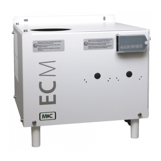
Page 14: Description
Description Figure 2 shows the ECM-2G ExII cooler unit Figure 2 ECM-2G ExII The cooler ECM-ExII is also suitable for wall mounting. The depth of the cooler housing is 270 mm [10.63”] without, and 316 mm [12.44”] with optionally mounted peristaltic pumps. The cooler ECM-ExII is conform to the system protection IP20 (EN 60529). -
Page 15: Function
Function The M&C gas cooler type ECM-ExII is a compressor cooler equipped with a status alarm for safe and continuous operation. Up to 2 Jet-stream heat exchangers made of Borosilicate glass, PVDF or stainless steel are located in a heat-insulated cooling block, where they are easy to access and to remove. Figure 3 shows a diagram of the heat exchanger function. -
Page 16: Receiving And Storing Of The Device
Receiving and storing of the device The ECM-ExII gas cooler is a complete pre-installed unit. Please remove the ECM-ExII carefully from the packaging. Check the scope of the delivery • specified on the delivery note. Please make sure that you have received all items stated on the delivery note. -
Page 17: Mounting
Mounting Do not mount or carry out any work at the gas cooler while potentially explosive atmosphere is present. The process and the environment of the cooler needs to be explosion-free (explosion-free zone) during mounting. A zone is declared as explosion-free zone, if it is free of explosive atmosphere. - Page 18 Follow these instructions to ensure the adequate sealing of the connections: Borosilicate glass heat exchangers with connections GL 18-6 respectively GL 25-12 (standard) Before assembly, check the GL coupling rings to see if the PTFE/silicon locking rings have been • damaged.
-
Page 19: Electrical Connections
Electrical connections Wrong supply voltage can destroy your cooler! When connecting the equipment, make sure that the supply voltage is Caution identical with the information provided on the model type plate! Only carry out work on live parts when the area has been proved to be „safe“. -
Page 20: Start-Up
Follow these instructions to connect the status alarm and power cables: release the screws (7 pcs.) from the cooler hood and remove the hood; • put the cables (6-12 mm) through one of the cable glands in the bottom plate, and connect them •... -
Page 21: Closing Down
Closing down The installation site of the cooler must be frost-free, even when the unit has been switched off! In case of a short-term decommissioning of the cooler no special measures Note are required. In case of a long-term decommissioning, we recommend to purge the cooler with inert gas or air to remove residual condensate entirely from the cooler. -
Page 22: Adding And Replacing The Heat Exchangers
Connect the cooler to earth (electrical bonding terminal). The bleeder resistor needs to have an overall value of < 10 Ω. Warning The intervals between servicing are dependent on the process and system conditions in your facility. The facility QA/QC plan should address the frequency for maintenance and should be updated based on your operations. -
Page 23: Cleaning The Fins Of The Condenser
19.2 Cleaning the fins of the condenser Dust on the fins of the condenser reduces the cooling capacity. Therefore, it is necessary to clean the fins frequently. The following steps are recommended: Shut off the gas flow; • Disconnect the power supply. •... -
Page 24: 19.3.2 Replacing The Pump Tubing
Pump head (outside the cooler housing) Cooler front panel Recommended mounting distance Pump motor (inside the cooler housing) Figure 6 SR25.2: Mounting distance between front panel and pump motor For detailed mounting instructions, see the SR25.2 instruction manual. The manual is available on our website www.mc-techgroup.com. Note 19.3.2 Replacing the pump tubing Aggressive condensate is possible. -
Page 25: Figure 7 Replacing The Pump Tubing
Figure 7 Replacing the pump tubing Disconnect the cooler from the power supply; • • Open tube connectors at the pump; Press conveying belt at the recessed grips and turn S-bolt clockwise up to limit stop; • Remove conveying belt and pull the old tubing at the tube bushings out of the guides;... -
Page 26: 19.3.3 Replacing Contact Pulleys And Springs
19.3.3 Replacing contact pulleys and springs Disconnect the cooler from the power supply; • • Unscrew the screws of the pump head (metric wrench size 5.5); • Remove the pump head from the motor shaft; Now the driver can be removed from the pump head and is ready for maintenance. •... -
Page 27: Operating Of The Built-In Electronic Temperature Controller
Operating of the built-in electronic temperature controller Only use temperature controller with part no. 01B8365. Note Only carry out any work at the temperature controller, when the process and the environment of the cooler is declared as an explosion-free zone. A zone is declared as explosion-free zone, if it is free of explosive atmosphere. -
Page 28: Trouble Shooting
Trouble shooting The following table gives an overview of possible errors and instructions for checking and repairing the unit (Applies only to the start-up period of the cooler). Error Possible reason Check/Repair Condensate in the gas outlet Ambient temperature < 5 °C [41 °F] Heat up the components downstream;... -
Page 29: Spare Parts List
Spare parts list The replacement interval for spare parts and consumables depends on the specific operating condition of the analyzer. The quantities recommended in the following table are based on experience. Your replacement intervals will be based on your operating conditions. Electric gas cooler ECM-ExII (C) Consumable parts (R) Recommended spare parts... -
Page 30: Appendix
Appendix Sample gas output dew point as a function of gas flow at 60 °C inlet dew point. • Circuit diagram ECM-ExII Drawing No.: 2456-5.01 • • Ex-certificates: ATEX, CSA, FM EU Declaration of conformity • Find more product information on our home page: www.mc-techgroup.com •... -
Page 31: Figure 10 Circuit Diagram Ecm-Exii (Drawing-No.: 2456-5.01)
Figure 10 Circuit diagram ECM-ExII (Drawing-No.: 2456-5.01) www.mc-techgroup.com ECM-ExII | 1.02.00... - Page 32 ECM-ExII | 1.02.00 www.mc-techgroup.com...
- Page 33 www.mc-techgroup.com ECM-ExII | 1.02.00...
- Page 34 ECM-ExII | 1.02.00 www.mc-techgroup.com...
- Page 35 www.mc-techgroup.com ECM-ExII | 1.02.00...
- Page 36 ECM-ExII | 1.02.00 www.mc-techgroup.com...
- Page 37 www.mc-techgroup.com ECM-ExII | 1.02.00...
- Page 38 ECM-ExII | 1.02.00 www.mc-techgroup.com...
- Page 39 www.mc-techgroup.com ECM-ExII | 1.02.00...
- Page 40 ECM-ExII | 1.02.00 www.mc-techgroup.com...
- Page 41 www.mc-techgroup.com ECM-ExII | 1.02.00...
Need help?
Do you have a question about the EC Series and is the answer not in the manual?
Questions and answers