M&C EC Series Instruction Manual
Electric gas cooler
Hide thumbs
Also See for EC Series:
- Instruction manual (44 pages) ,
- Instruction manual (40 pages) ,
- Instruction manual (40 pages)

Related Manuals for M&C EC Series


Summary of Contents for M&C EC Series
- Page 1 Electric Gas Cooler Series EC ® ECS-SS HF EX2 II 3 G Ex nA nC IIC T4 Gc Instruction Manual Version 1.00.00...
- Page 2 Dear customer, Thank you for buying our product. In this instruction manual you will find all necessary information about this M&C product. The information in the instruction manual is fast and easy to find, so you can start using your M&C product right after you have read the manual. If you have any question regarding the product or the application, please don’t hesitate to contact M&C or your M&C authorized distributor.
-
Page 3: Table Of Contents
List of Contents General information ........................ 4 Declaration of conformity ....................... 4 Safety instructions ........................5 Information and safety instructions for using the cooler in hazardous areas ....5 Warranty ..........................6 Used terms and signal indications ..................6 Introduction ..........................8 Application .......................... -
Page 4: General Information
Head Office M&C TechGroup Germany GmbH Rehhecke 79 40885 Ratingen Germany Telephone: 02102 / 935 - 0 Fax: 02102 / 935 - 111 E - mail: info@mc-techgroup.com www.mc-techgroup.com GENERAL INFORMATION The product described in this manual has been built and tested in our production facility. All M&C products are packed to be shipped safely. -
Page 5: Safety Instructions
SAFETY INSTRUCTIONS Follow these basic safety procedures when using this equipment: Read these operating instructions carefully before start-up and use of the equipment! The information and warnings given in these operating instructions must be heeded. Work on electrical equipment is only to be carried out by trained specialists as per the regulations currently in force. -
Page 6: Warranty
WARRANTY In case of a device failure, please contact immediately M&C or your M&C authorized distributor. We have a warranty period of 12 months from the delivery date. The warranty covers only appropriately used products and does not cover the consumable parts. Please find the complete warranty conditions in our terms and conditions. - Page 7 High voltages! Protect yourself and others against damages which might be caused by high voltages. Toxic! Acute toxicity (oral, dermal, inhalation)! Toxic when in contact with skin, swollowed or inhaled. Corrosive! These substances destroy living tissue and equipment upon contact. Do not breathe vapors;...
-
Page 8: Introduction
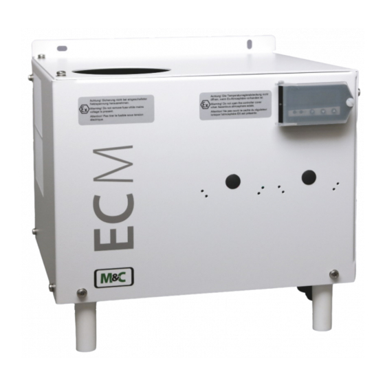
INTRODUCTION The ECS-SS HF EX2 gas cooler is used in gas analysis to lower the dew point of high flow rates of humid gases to avoid condensation in the analyzer for applications where fast response times are requested. An extremely stable gas dew point avoids water vapor cross sensitivity and volumetric errors. APPLICATION Figure 1shows a typical example of an application for installation of an ECS-SS HF EX2 gas cooler unit. -
Page 9: Technical Data
TECHNICAL DATA Gas Cooler Series EC ® ECS-SS HF EX2 Protection class II 3 G Ex nA nC IIC T4 Gc Number of heat exchanger Gas flow rate 1500 Nl/h* for gas inlet dew point 70 °C [158 °F] and 1000 Nl/h* for gas inlet dew point 80 °C [176 °F] Ambient temperature +5 to +40 °C [41 to 104 °F]... -
Page 10: Description
DESCRIPTION High-output, maintenance-free and self-controlling. Intelligent detailed solutions provide optimum cooling of the sample gas and direct separation of condensate to avoid contamination effects. The new controlled compressor cooling system and the special design of the jet stream heat exchanger guarantee an optimum dew point reduction to a low, stable value. -
Page 11: Function
FUNCTION The especially for gas analysis designed M&C ECS-SS HF EX2 gas cooler is a compressor cooler equipped with status alarm for safe continuous operation. The heat exchanger made of stainless steel works on the principle of Jet-Stream. The construction of the Jet-Stream-heat exchanger ensures a good condensate pre-separation and an optimal drying of the sample gas. -
Page 12: Reception And Storage
RECEPTION AND STORAGE The ECS-SS HF EX2 gas cooler is a complete pre-installed unit. • Remove the cooler and any special accessories immediately after arrival carefully from the shipping packaging, and check the scope of delivery according to the delivery note; •... -
Page 13: Supply Connections
SUPPLY CONNECTIONS 14.1 HOSE CONNECTIONS The connection for sample gas in- and outlet is located on the upper part of the heat exchangers at the G ¼” female threads. Correspondingly tube or hose connectors are optional available at M&C. Do not mix up the tube connections for sample gas inlet and outlet; connections are marked by arrows on the heat exchangers. -
Page 14: Figure 3 Electrical Connection Ecs-Ss Hf Ex2
Only carry out work on live parts, when the area has been proved to be „safe“. W a r n i n g Only carry out work on the protective cover in front of the temperature controller, when the area has been proved to be „safe“. Attention must be paid to the requirements of IEC 364 (DIN VDE 0100) when setting high-power electrical units with nominal voltages of up to 1000 V, together with the associated standards and stipulations. -
Page 15: Start-Up
The power connections are located behind the removable front plate of the cooler housing at terminal X0. The potential free contact outputs of the collective status alarm are to be connected at terminal X3. For the cable bushings through the bottom plate of the cooler housing 2 cable glands 2 x M20 x 1.5, clamping range 6-12 mm are available (see Figure 2). -
Page 16: Closing Down
The status contacts must be connected to the external sample gas pump or to a valve in the sample gas line to protect the entire analysis system by immediately cutting off the gas supply in the event of error messages from the cooler! N o t e CLOSING DOWN The site where the cooler is installed, must also remain frost-free even... -
Page 17: Maintenance
MAINTENANCE Qualified personnel The inspections and maintenance work described in this chapter can be carried out by qualified personnel. The following knowledge is at least required for the work: Instructed person in EX-protection • Trained person in the electrotechnical field •... -
Page 18: Maintenance Of The Optional Mounted Peristaltic Pump, Type Sr25.6
17.2 MAINTENANCE OF THE OPTIONAL MOUNTED PERISTALTIC PUMP, TYPE SR25.6 Before starting any maintenance work, make sure that any work done on the device is in compliance with all relevant regulations and standards. Dangerous voltage! Disconnect power supply before opening the device for access. Warning Make sure that all external power supplies are disconnected. -
Page 19: 17.2.1 Changing The Pump Tubing
17.2.1 CHANGING THE PUMP TUBING 1 Conveying belt 2 S-bolt 3 Tubing set 4 contact pulley 5 springs Figure 4 Changing the pump tubing For changing the pump tubing please proceed as follows: Unplug the pump from the mains voltage. The device needs to be voltage free. •... -
Page 20: 17.2.2 Changing Contact Pulleys And Springs
17.2.2 CHANGING CONTACT PULLEYS AND SPRINGS While mounting, make sure that the center of rotation and the driver are aligned. Use genuine spare parts only! Note Follow these instructions to change the contact pulley and springs: • Disconnect the peristaltic pump from power supply •... -
Page 21: 17.2.3 Reassembly Of The Driver
The dent prevents rotation of the axis worn out Figure 7 Check of axes and rolls The springs may come in different colorings. This is not a quality impairment. Make sure to use the right spring strength. This can be identified by the spring wire diameter. -
Page 22: 17.2.4 Cleaning The Pump Head
17.2.4 CLEANING THE PUMP HEAD When changing flexible tube or other parts, inspect all parts for dirt before assembling the pump • head and clean them if necessary. • We recommend to clean the parts with a dry cloth. Solvent should not be used, because it can damage the plastics and synthetic rubber parts. -
Page 23: Operating Of The Built-In Electronic Temperature Controller
OPERATING OF THE BUILT-IN ELECTRONIC TEMPERATURE CONTROLLER Only use temperature controller with Part No. 01B8365. Note Only carry out any work at the temperature controller, when the process and the environment of the cooler is declared as an explosion-free zone. A zone is declared as explosion-free zone, if it is free of explosive atmosphere. -
Page 24: Trouble Shooting
TROUBLE SHOOTING The following table shows possible reasons for error and how to correct them (not applicable for the running-up phase of the cooler). Error Possible reason Check/Repair Condensate in the gas outlet Heat up the components downstream; Ambient temperature < 5 °C Keep the operational data (chapter 9);... -
Page 25: Spare Parts List
SPARE PARTS LIST Wear, tear and replacement part requirements depend on specific operating conditions. The recommended quantities are based on experience and are not binding. Electric gas cooler ECS-SS HF (C) Consumable parts (R) Recommended spare parts (S) Spare parts Recommended quantity being in operation [years] Part No. -
Page 26: Appendix
APPENDIX • Sample output dew point (ambient temperature 20 °C [68 °F]) depending on gas flow rate • Circuit diagram ECS-SS HF EX2 Further product documentation can be seen and downloaded from our home page: www.mc-techgroup.com Instruction manual peristaltic pump SR25.2, SR25.3, SR25.6 •... -
Page 27: Figure 9 Sample Gas Outlet Dew Point Characteristics
Sample output dew point (ambient temperature 20 °C [68 °F], inlet dew point 60 to 80°C [140 to 176 °F], sample temperature 150 °C [302 °F]) depending on gas flow rate 60°C 70°C 80°C 1000 1500 Sample gas flow Nl/hr Figure 9 Sample gas outlet dew point characteristics www.mc-techgroup.com ECS-SS HF EX2 | 1.00.00... -
Page 28: Figure 10 Circuit Diagram Ecs-Ss Hf Ex2
Figure 10 Circuit diagram ECS-SS HF EX2 ECS-SS HF EX2 | 1.00.00 www.mc-techgroup.com... -
Page 29: Figure 11 Ec Declaration Of Conformity
Figure 11 EC declaration of conformity www.mc-techgroup.com ECS-SS HF EX2 | 1.00.00...
Need help?
Do you have a question about the EC Series and is the answer not in the manual?
Questions and answers