Sign In
Upload
Download
Table of Contents
Contents
Add to my manuals
Delete from my manuals
Share
URL of this page:
HTML Link:
Bookmark this page
Add
Manual will be automatically added to "My Manuals"
Print this page
×
Bookmark added
×
Added to my manuals
Manuals
Brands
M&C Manuals
Accessories
LA Series
Instruction manual
M&C LA Series Instruction Manual
Liquid alarm sensors for conductive media, flow chambers, with electronic controllers
Hide thumbs
1
2
Table Of Contents
3
4
5
6
7
8
9
10
11
12
13
14
15
16
17
18
19
20
21
22
23
24
25
26
27
28
29
page
of
29
Go
/
29
Contents
Table of Contents
Bookmarks
Table of Contents
Table of Contents
1 General Information
2 Declaration of Conformity
3 Safety Instructions
4 Warranty
5 Used Terms and Signal Indications
6 Introduction
7 Application
8 Technical Data
9 Description
10 Receipt of Goods and Storage
11 Installation Instructions and Dimensions
Figure 1 Flow Chamber LS with Liquid Sensor LA1S
Figure 2 Flow Chamber LS 25 with Liquid Sensor LA25S
12 Mounting
Factory Pre-Assembly of Complete Monitoring Units
Figure 3 Liquid Sensor LA1S with Filter F
Mounting the Sensor LA1S into the Universal Filter
Mounting of the Sensor LA1S into the Flow Chamber LS
Mounting the Sensor LA25S Onto the Universal Filter
Figure 4 Mounting of the Sensor LA1S into Flow Chamber LS
Mounting the Sensor LA25S into the Flow Chamber LS25
13 Supply Connections
Electrical Connections
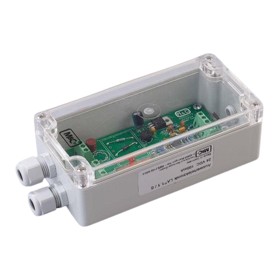
Electronic Controller LA1.1
Electronic Controller LA1.4
Figure 5 Electrical Connection and Dimensions LA1.1
Figure 6 Electrical Connection and Dimensions LA1.4
Pneumatic Connections
Figure 7 LA1.4 Assembly Diagram
14 Commissioning
Commissioning with a Dry Sensor
Function Test
Adjustment of Sensitivity
Adjustment of Alarm Holding Function
15 Closing down
16 Maintenance and Repair
18 Appendix
Figure 8 Flow Diagram LA1.1, 115/230 V 50/60 Hz
Figure 9 Flow Diagram LA1.1, 24V AC/DC
Figure 10 Flow Diagram LA1.4, 115/230V 50/60Hz
Figure 11 Flow Diagram LA1.4, 24V AC/DC
17 Spare Parts List
Advertisement
Quick Links
Download this manual
Liquid Alarm Sensors for Conductive Media
®
Series LA
LA1S, LA25S
Flow Chambers
LS, LS25
With Electronic Controllers
LA1.1, LA1.4
Instruction Manual
Version 1.01.01
Table of
Contents
Previous
Page
Next
Page
1
2
3
4
5
Advertisement
Table of Contents
Need help?
Do you have a question about the LA Series and is the answer not in the manual?
Ask a question
Questions and answers
Related Manuals for M&C LA Series
Accessories M&C LA1S Instruction Manual
Liquid alarm sensors for conductive media, flow chambers, with electronic controllers (29 pages)
Accessories M&C LA1.4 Instruction Manual
Liquid alarm sensors for conductive media, flow chambers, with electronic controllers (29 pages)
Accessories M&C LC Series Instruction Manual
Gas and liquid cooler (18 pages)
Accessories M&C LG Series Instruction Manual
Gas and liquid cooler (18 pages)
Accessories M&C LT Series Instruction Manual
Gas and liquid cooler (18 pages)
Accessories M&C PSP4000-H Instruction Manual
Electrically-heatedand portablegas sample probe (27 pages)
Accessories M&C EC Series Instruction Manual
Electric gas cooler (29 pages)
Accessories M&C ECM Series Instruction Manual
Electric gas cooler (29 pages)
Accessories M&C EC Series Instruction Manual
Electric gas cooler (40 pages)
Accessories M&C EC Series Instruction Manual
Ultra low gas cooler (40 pages)
Accessories M&C EC-30C Instruction Manual
Ultra low gas cooler (78 pages)
Accessories M&C EC Series Instruction Manual
Electric gas cooler (41 pages)
Accessories M&C SP Series Instruction Manual
Compact gas sample probe (34 pages)
This manual is also suitable for:
La1s
La25s
Ls
Ls25
La1.1
La1.4
Table of Contents
Print
Rename the bookmark
Delete bookmark?
Delete from my manuals?
Login
Sign In
OR
Sign in with Facebook
Sign in with Google
Upload manual
Upload from disk
Upload from URL


Need help?
Do you have a question about the LA Series and is the answer not in the manual?
Questions and answers