Table of Contents
Advertisement
Quick Links
Advertisement
Table of Contents

Related Manuals for Pro TM1018


Summary of Contents for Pro TM1018
- Page 1 Product Manual MNX10013 REV C MODEL TM1018 Accelerometer Verification Meter...
- Page 2 Introduction.................….… 2 Description..................2 Section II Installation Connecting the TM1018..............3 Section III Operation Turning on the TM1018..............4 Circuit Integrity (LED Readout)............4 Diagnostic Check List................. 4 Bias Voltage LCD Readout..............4 Section IV Maintenance Battery Life..................5 General....................5 Warranty.....................
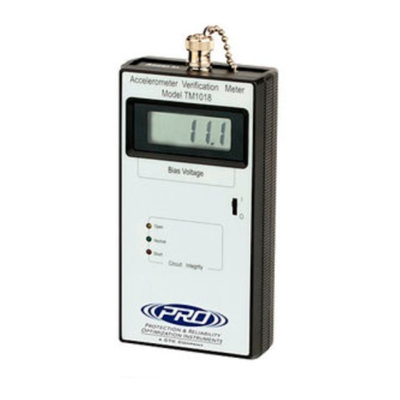
- Page 3 User manuals are provided with the system for all configurable internal components. Description The TM1018 meter indicates if your accelerometer, cable and/or switch box is in working condition. It will also display the exact voltage of your accelerometer. MNX10013 / REV C...
- Page 4 Section II Installation Connecting the TM1018 Your TM1018 Test Meter comes supplied with 3 cables for connection. Each cable has a BNC plug to connect to the top of the Test Meter. The other end of the cable terminates as follows: •...
- Page 5 Section III Operation Turning on the TM1018 Turn on the TM1018 Verification Meter by moving the switch to the ‘I’ position. Circuit Integrity (LED Readout) – Diagnostic Check List Normal: Indicates that the accelerometer is connected properly Green Light and that the accelerometer is within operating specifications.
- Page 6 Warranty If any PRO product should ever fail, we will repair or replace it at no charge, as long as the product was not subjected to misuse, natural disasters, improper installation or modification which caused the defect.
Need help?
Do you have a question about the TM1018 and is the answer not in the manual?
Questions and answers