Table of Contents
Advertisement
Quick Links
Advertisement
Table of Contents

Subscribe to Our Youtube Channel
Related Manuals for Chauvin Arnoux PEL 106


Summary of Contents for Chauvin Arnoux PEL 106
- Page 1 EN - User’s manual PEL 106 Power energy logger...
- Page 2 Thank you for purchasing a PEL106 power and energy logger. For best results from your instrument: „ read these operating instructions carefully, „ comply with the precautions for use. WARNING, risk of DANGER! The operator must refer to these instructions whenever this danger symbol appears. WARNING! Risk of electric shock.
- Page 3 PRECAUTIONS FOR USE This instrument complies with safety standard IEC/EN 61010-2-030 or BS EN 61010-2-030, the leads comply with IEC/EN 61010- 031 or BS EN 61010-031 for voltages of 1000 V in measurement category IV and the current sensors comply with IEC/EN 61010- 2-032 or BS EN 61010-2-032.
-
Page 4: Table Of Contents
CONTENTS 1. FIRST USE ....................................5 1.1. Delivery condition ................................5 1.2. Accessories .................................6 1.3. SPARE PARTS ................................6 2. PRESENTATION OF THE INSTRUMENT ..........................7 2.1. Description ...................................7 2.2. Front panel ..................................8 2.3. Terminal block ................................9 2.4. Installation of the coloured inserts ..........................9 2.5. -
Page 5: First Use
1. FIRST USE 1.1. DELIVERY CONDITION Œ PEL 106 POWER & ENERGY LOGGER Ž ’ “ ‘ ” ATTESTATION DE VERIFICATION CHECKING ATTESTATION • 190, rue Championnet 75876 PARIS Cedex 18 Numéro de l'appareil : FRANCE Equipment number... -
Page 6: Accessories
1.2. ACCESSORIES „ MiniFlex MA193 250 mm ® „ MiniFlex MA193 350 mm ® „ MiniFlex MA194 250 mm ® „ MiniFlex MA194 350 mm ® „ MiniFlex MA194 1000 mm ® „ MiniFlex MA196 350 mm tight ® „ AmpFlex A193 450 mm ®... -
Page 7: Presentation Of The Instrument
2. PRESENTATION OF THE INSTRUMENT 2.1. DESCRIPTION PEL: Power & Energy Logger (power and energy logger) The PEL106 is a DC, single-phase, two-phase, and three-phase (wye and D) power and energy logger in a rugged sealed housing. The PEL has all power/energy recording functions needed for most of the world's 50Hz, 60Hz, 400Hz, and DC distribution net- works, with many connection possibilities to suit different installations. -
Page 8: Front Panel
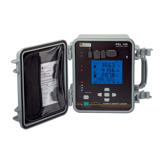
Connector for external status information. power supply (optional USB connector. SIM card slot. mains power unit). QR code. PEL 106 POWER & ENERGY LOGGER LCD display unit. Selection key. Bag in which to stow Directional keypad: four naviga- the sealing plugs of tion keys and one validation key On/Off key. -
Page 9: Terminal Block
2.3. TERMINAL BLOCK 4 current inputs (specific 4-point connectors). 5 voltage inputs (safety connectors). VE/GND Figure 5 The plugs keep the terminals tight (IP67) when they are not in use. When you connect a current sensor or a voltage lead, screw it tight to keep the instrument tight. Stow the plugs in the bag attached to the cover of the instrument. -
Page 10: Functions Of The Keys
2.5. FUNCTIONS OF THE KEYS Description On/Off Key: Switches the instrument on or off. Remark: The instrument cannot be switched off when it is connected to mains (whether by the measurement inputs or by the mains power unit) or when recording is in progress or pending. Selection key: A long press activates or deactivates the Bluetooth link, the Wi-Fi link or the 3G-UMTS/GPRS link and starts or stops recording. -
Page 11: Indicators
The bottom and top strips provide the following indications: Icon Description Indicator of a reversal of phase order or a missing phase (displayed for three-phase distribution networks, and only in measurement mode; see the explanation below) Data available for recording. Indication of the power quadrant. -
Page 12: Memory Card
Indicators Colour and function Green/red indicator: SD card Green indicator lit: the SD card is recognized and not locked. Red indicator lit: SD card missing or locked or not recognized. Red indicator blinking: SD card being initialized. Indicator blinking alternately red and green: SD card full. Indicator light green and blinking: the SD card will be full before the end of the recording session in progress. -
Page 13: Configuration
3. CONFIGURATION The PEL must be configured before any recording. The various steps in this configuration are: „ Set up the USB link, the Bluetooth link, the Ethernet link, the Wi-Fi link or the 3G-UMTS/GPRS link. „ Choose the connection according to the type of distribution network. „... -
Page 14: Battery Charging
110 - 250 V 50 / 60 Hz „ Withdraw the elastomer cap that protects the power supply connector. PEL 106 POWER & ENERGY LOGGER „ Connect the mains power unit to the instru- ment and to mains. The instrument comes on. -
Page 15: Connection By Wi-Fi, Bluetooth Or By The 3G-Umts/Gprs Link
Then, whichever link was chosen, open the PEL Transfer software (see § 5) to connect the instrument to the PC. Connecting the USB or Ethernet cable does not power up the instrument or charge the battery. For the Ethernet LAN link, the PEL has an IP address. When you configure the instrument with the PEL Transfer software, if the "Activate DHCP"... -
Page 16: Configuring The Instrument
If needed, the pairing code is 0000. This code cannot be modified in PEL Transfer. With the 3G-UMTS/GPRS link, the data transmitted by the device pass via an IRD server hosted by Chauvin Arnoux. To receive them on your PC, you must enable the IRD server in PEL Transfer. - Page 17 3.5.1. TYPE OF NETWORK To change the network, press the Enter key. The name of the network blinks. Use the and keys to choose another network from among those in the list below. Designation Network 1P-2W Single-phase, 2-wire 1P-3W Single-phase, 3-wire 3P-3W∆2...
- Page 18 3.5.3. NOMINAL PRIMARY VOLTAGE Press the key to go to the next screen. Figure 14 To change the nominal primary voltage, press the Enter key. Use the , , and keys to choose the voltage, between 50 and 650,000 V. Then validate by pressing the Enter key.
- Page 19 Depending on the type of current sensor, MiniFlex /AmpFlex , MN clamp, or adapter unit, enter the nominal primary current. To ® ® do this, press the Enter key. Use the , , and keys to choose the current. „...
-
Page 20: Information
3.6. INFORMATION To enter the Information mode, press the or key until the symbol is selected. Use the and keys to scroll the information of the instrument: „ Type of network „ Nominal primary voltage „ Nominal secondary voltage „... - Page 21 „ Nominal primary current of the neutral (if a sensor is connected to the terminal) „ Aggregation period „ Date and time „ IP address (scrolling)
- Page 22 „ Wi-Fi address (scrolling) „ 3G address (scrolling) „ Software version „ 1 number = software version of the DSP „ 2 number = software version of the microprocessor „ Scrolling serial number (also on the QR code label glued to the inside of the cover of the PEL) After 3 minutes with no action on the Enter or Navigation key, the display returns to the measurement screen...
-
Page 23: Use
4. USE When the instrument has been configured, you can use it. 4.1. DISTRIBUTION NETWORKS AND CONNECTIONS OF THE PEL Start by connecting the current sensors and the voltage measurement leads to your installation according to the type of distribution network. - Page 24 4.1.2. SPLIT-PHASE, 3-WIRE (SPLIT-PHASE FROM A CENTRE-TAP TRANSFORMER): 1P-3W „ Connect the N terminal to the neutral. „ Connect the VE/GND terminal to the earth (optional on this type of network). „ Connect the V1 terminal to the L1 phase. „...
- Page 25 ∆ 4.1.3.3. Three-phase, 3-wire open (with 2 current sensors): 3P-3W02 „ Connect the VE/GND terminal to the earth. „ Connect the V1 terminal to the L1 phase. „ Connect the V2 terminal to the L2 phase. „ Connect the V3 terminal to the L3 phase. „...
- Page 26 4.1.3.6. Three-phase, 3-wire, wye (with 3 current sensors): 3P-3WY „ Connect the VE/GND terminal to the earth. „ Connect the V1 terminal to the L1 phase. „ Connect the V2 terminal to the L2 phase. „ Connect the V3 terminal to the L3 phase. „...
- Page 27 4.1.4.2. Three-phase, 4-wire, wye, balanced (with 2 current sensors): 3P-4WYB „ Connect the N terminal to the neutral. „ Connect the VE/GND terminal to the earth. „ Connect the V1 terminal to the L1 phase. „ Connect the IN current sensor to the neutral. „...
- Page 28 ∆ 4.1.5. THREE-PHASE, 4-WIRE Three-phase 4-wire ∆ (High Leg) configuration. No voltage transformer is connected: the installation measured is assumed to be a LV (low-voltage) distribution network. ∆ 4.1.5.1. Three-phase, 4-wire ∆ (with 4 current sensors): 3P-4W „ Connect the N terminal to the neutral. „...
- Page 29 4.1.6. DC SUPPLY NETWORKS 4.1.6.1. DC 2-wire: DC-2W „ Connect the N terminal to the common conductor. „ Connect the VE/GND terminal to the earth. „ Connect the V1 terminal to the +1 conductor. „ Connect the IN current sensor to the common conductor. „...
-
Page 30: Using External Data Loggers
4.2. USING EXTERNAL DATA LOGGERS The PEL106 can connect itself with up to four L452 Data Loggers. The connection is in Bluetooth. It is configured using the PEL Transfer software. The L452 Data Logger can be used: „ to record DC voltages up to 10V, „... - Page 31 4.4.1. MEASUREMENT MODE The display depends on the network configured. Press the key to go from one screen to the next. Single-phase, 2-wire (1P-2W) ϕ (I tan ϕ...
- Page 32 Two-phase, 3-wire (1P-3W) ϕ (I ϕ (V ϕ (I ϕ (I tan ϕ...
- Page 33 Three-phase, 3-wire, unbalanced (3P-3WD2, 3P-3WD3, 3P-3WO2, 3P-3WO3, 3P-3WY2, 3P-3WY3) ϕ (I ϕ (I ϕ (I ϕ (U ϕ (U ϕ (U ϕ (I ϕ (I ϕ (I tan ϕ...
- Page 34 Three-phase, 3-wire ∆, balanced (3P-3W∆b) ϕ (I tan ϕ...
- Page 35 Three-phase, 4-wire, unbalanced (3P-4WY, 3P-4WY2, 3P-4WD, 3P-4WO) ϕ (I ϕ (I ϕ (I ϕ (V ϕ (V ϕ (V ϕ (U ϕ (U ϕ (U ϕ (I ϕ (I ϕ (I *: For 3P-4WD and 3P-4WO networks...
- Page 36 tan ϕ Three-phase, 4-wire, wye, balanced (3P-4WYb)
- Page 37 ϕ (I tan ϕ DC 2-wire, (dC-2W) DC 3-wire, (dC-3W)
- Page 38 DC 4-wire, (dC-4W)
- Page 39 4.4.2. ENERGY MODE The powers displayed are the total powers. The energy depends on the duration; typically it is available at the end of 10 or 15 minutes or at the end of the aggregation period. Press the Enter key for more than 2 seconds to obtain the powers by quadrant (IEC 62053-23). The display unit indicates PArt to specify that the values are partial.
- Page 40 Ep-: Total active energy delivered (by the source) in kWh Eq1: Reactive energy consumed (by the load) in the inductive quadrant (quadrant 1) in kvarh. Eq2: Reactive energy delivered (by the source) in the capacitive quadrant (quadrant 2) in kvarh. Eq3: Reactive energy delivered (by the source) in the inductive quadrant (quadrant 3) in kvarh.
- Page 41 Eq4: Reactive energy consumed (by the load) in the capacitive quadrant (quadrant 4) in kvarh. Es+: Total apparent energy consumed (by the load) in kVAh Es-: Total apparent energy delivered (by the source) in kVAh DC networks Ep+: Total active energy consumed (by the load) in kWh...
- Page 42 Ep-: Total active energy delivered (by the source) in kWh 4.4.3. HARMONICS MODE The display depends on the network configured. The harmonics display is not available for DC networks. The display unit indicates "No THD in DC mode". Single-phase, 2-wire (1P-2W) I_THD V_THD Two-phase, 3-wire (1P-3W)
- Page 43 _THD _THD _THD Three-phase, 3-wire, unbalanced (3P-3WD2, 3P-3WD3, 3P-3WO2, 3P-3WO3, 3P-3WY2, 3P-3WY3) _THD _THD _THD _THD _THD _THD Three-phase, 3-wire ∆, balanced (3P-3W∆b) _THD = I _THD _THD = I _THD _THD...
- Page 44 _THD _THD = U _THD _THD = U _THD Three-phase, 4-wire, unbalanced (3P-4WY, 3P-4WY2, 3P-4WD, 3P-4WO) _THD _THD _THD _THD _THD _THD _THD Three-phase, 4-wire, wye, balanced (3P-4WYb) _THD _THD _THD...
- Page 45 _THD _THD _THD 4.4.4. MAXIMUM MODE Depending on the option selected in PEL Transfer, these may be the maximum aggregated values of the recording in progress or of the last record, or the maximum aggregated values since the last reset. The maximum display is not available for DC networks.
- Page 46 Two-phase, 3-wire (1P-3W)
- Page 47 Three-phase, 3-wire (3P-3WD2, 3P-3WD3, 3P-3WO2, 3P-3WO3, 3P-3WY2, 3P-3WY3, 3P-3W∆b)
- Page 48 Three-phase, 4-wire (3P-4WY, 3P-4WY2, 3P-4WD, 3P-4WO), 3P-4WYb) For the balanced network (3p-4WYb), I is not displayed.
-
Page 50: Software And Application
5. SOFTWARE AND APPLICATION 5.1. PEL TRANSFER SOFTWARE 5.1.1. FUNCTIONS PEL transfer software is used to: „ Connect the instrument to the PC by Wi-Fi, Bluetooth, USB, Ethernet or 3G-UMTS/GPRS. „ Assign a name to the instrument, choose the brightness and contrast of the display unit, disable or enable the Selection key of the instrument, set the date and time, format the SD card, etc. -
Page 51: Pel Application
5.2. PEL APPLICATION The Android application provides some of the functions of the PEL Transfer software. It enables you to connect to your instrument remotely. Find the application by typing PEL Chauvin Arnoux. Install the application on your smartphone or tablet. - Page 52 The application has 3 tabs. is used to connect the instrument: „ by Bluetooth. Activate Bluetooth on your smartphone or tablet and pair with your PEL. „ or by Ethernet. Connect your instrument to the Ethernet network using a cable, then enter its IP address (see §3.6), the port, and the network protocol (this information is available in PEL Transfer).
-
Page 53: Technical Characteristics
6. TECHNICAL CHARACTERISTICS Uncertainties are expressed as a percentage (%) of the reading (R) plus an offset: ± (a%R + b) 6.1. REFERENCE CONDITIONS Parameter Reference conditions Ambient temperature 23 ± 2 °C Relative humidity 45% RH to 75% RH Voltage No DC component in the AC, no AC component in the DC (<... - Page 54 6.2.3. INTRINSIC UNCERTAINTY (NOT COUNTING THE CURRENT SENSORS) The uncertainties in the tables below are given for the "1s" and aggregated values. For the "200ms" measurements, the uncertain- ties must be doubled 6.2.3.1. Specifications at 50/60Hz Quantities Measurement range Intrinsic uncertainty Frequency (f) [42.5;...
- Page 55 Quantities Measurement range Intrinsic uncertainty PF = 1 V = [100V; 1,000V] ± 1% R I = [10 % Inom; 120% Inom] Table 7 „ Inom is the measured current when the output from the current sensor is 1V. „ Pnom and Snom are the active and apparent powers for V = 1,000 V, I = Inom, and PF = 1. „...
- Page 56 6.2.3.3. Specifications in DC Quantities Measurement range Typical intrinsic uncertainty Voltage (V) V = [100V; 1,000 V] ± 0.2% R ± 0.2 V Neutral-earth voltage (V V = [2 V; 1,000 V] ± 0.2% R ± 0.2 V Current (I) I = [5% Inom;...
- Page 57 6.2.4.2. Characteristics The measurement ranges are those of the current sensors. These are sometimes different from those of the PEL. Refer to the user manual provided with the current sensor. a) AmpFlex A196A or AmpFlex A193 ® ® „ Press on both sides of the opening device to unlock the flexible coil. Open it, then place it around the conductor carrying the current to be measured (only one conductor per coil).
- Page 58 b) MiniFlex MA193, MA194 and MA196 ® MiniFlex MA193 and MA196 ® Nominal range 100 / 400 / 2,000 Aac Measurement range 200 mA to 2,400 Aac Length = 250 mm; Ø = 70 mm (MA 193 only) Maximum clamping diameter Length = 350 mm;...
- Page 59 d) C193 clamp C193 clamp Nominal range 1,000 Aac for f ≤ 10 kHz Measurement range 1A to 1,200 Aac max (I >1,000A for 5 minutes at most) Maximum clamping diameter 52 mm Influence of the position of the con- <...
- Page 60 g) E3N clamp with adapter E3N clamp Nominal range 10 Aac/dc, 100 Aac/dc 100 mV/A range: 0.05 o 10 Aac/dc Measurement range 10 mV/A range: 0.5 o 100 Aac/dc Maximum clamping diameter 11.8 mm Influence of the position of the <...
- Page 61 6.2.4.3. Intrinsic uncertainty The intrinsic uncertainties of the current measurements and of the phase must be added to the intrinsic uncertainties of the instrument for the quantity concerned: power, energies, power factors, tan Φ, etc. The following characteristics are given for the reference conditions of the current sensors. Characteristics of the current sensors (output 1V at Inom) Typical Intrinsic...
- Page 62 Characteristics of the AmpFlex and MiniFlex ® ® Intrinsic Intrinsic Intrinsic Typical uncer- Current Current uncertainty I nominal uncertainty at 50/ uncertainty tainty on ϕ at sensor (RMS or DC) on ϕ 60Hz at 400Hz 400 Hz at 50/60 Hz [200 mA;...
-
Page 63: Communication
6.3. COMMUNICATION 6.3.1. BLUETOOTH Bluetooth 2.1 Class 1 (range up to 100m in line of sight) Default pairing code: 000 Nominal output power: +15 dBm Nominal sensitivity: -82 dBm Rate: 115.2 kbits/s 6.3.2. USB Type B connector USB 2 6.3.3. NETWORK RJ45 connector with 2 built-in LEDs 100 Base T Ethernet 6.3.4. -
Page 64: Environmental Characteristics
6.5. ENVIRONMENTAL CHARACTERISTICS „ Indoor and outdoor use. „ Altitude: „ Operation: 0 to 2,000 m „ Storage: 0 to 10,000 m „ Temperature and relative humidity: % RH 1 = Reference range 1 + 2 = Operation range 1 + 2 + 3 = Storage range T (°C) 20 26 Figure 37... -
Page 65: Radio Emission
6.9. RADIO EMISSION The devices are compliant with the 2014/53/EU RED directive and FCC Regulations. https://www.chauvin-arnoux.com/COM/CA/doc/Declaration_of_conformity_PEL106.pdf FCC certification Bluetooth FCC QOQWT11u Wi-Fi FCC QOQWF121 FCC XPY-LISAU200 6.10. MEMORY CARD The PEL accepts FAT32-formatted SD, SDHC and SDXC cards up to a capacity of 32GB. The SDXC cards must be formatted in the instrument. -
Page 66: Maintenance
7. MAINTENANCE Except for the attachments of the tight connectors and the caps of the terminals, the instrument contains no parts that can be replaced by personnel who are not specially trained and accredited. Any unauthorized repair or replacement of a part by an “equivalent” may gravely impair safety. Regularly check the condition of the O-rings in the leads. -
Page 67: Warranty
8. WARRANTY Except as otherwise stated, our warranty is valid for 24 months starting from the date on which the equipment was sold. Extract from our General Conditions of Sale provided on request. The warranty does not apply in the following cases: „... -
Page 68: Appendix
9. APPENDIX 9.1. MEASUREMENTS 9.1.1. DEFINITION The calculations are performed in accordance with standards IEC 61557-12, IEC 61000-4-30, and IEEE 1459. Geometrical representation of the active and reactive powers: Load Source Active power Active power supplied consumed Reactive power consumed φ... - Page 69 9.1.2.2. Locking of the sampling frequency „ As default, the sampling frequency is locked to V1. „ If V1 is missing, the instrument attempts to lock to V2, then to V3, I1, I2, and I3. 9.1.2.3. AC/DC The PEL makes AC and DC measurements for AC and DC distribution networks. AC or DC is selected by the user. The AC + DC values are available with PEL Transfer.
-
Page 70: Measurement Formulas
9.2. MEASUREMENT FORMULAS Most of the formulas are taken from standard IEEE 1459. The PEL measures or calculates the values below for one cycle (128 samples per period from 16 to 400Hz. These values are not accessible to the user. The PEL then calculates a value aggregated over 10 cycles (50Hz), 12 cycles (60Hz), or 80 cycles (400Hz) ("200ms"... - Page 71 Quantities Formulas Remarks × AC fundamental apparent power − − L = 1, 2 or 3 PF = AC power factor (PF L = 1, 2 or 3 − AC active power unbalance (Pu) − AC harmonic active powers (P ϕ...
- Page 72 I1, I2, I3 are the currents flowing in the phase conductors of the installation measured. is the current flowing in the neutral conductor of the installation measured. The lower-case i1, i2, i3 designate the sampled values. For some quantities linked to the powers, the "generated" and "consumed" quantities are counted separately for the values ag- gregated from the "1s"...
-
Page 73: Electrical Networks Allowed
Quantities Formulas Remarks Φ − Φ (Φ AC generated Tan − − DC measurements ∑ × DC consumed active power (P L = 1, 2, 3 or T L+dc ∑ − × × − − DC generated active power (P L = 1, 2, 3 or T L-dc AC+DC measurements... - Page 74 Distribution Reference Phase Abbreviation Remarks network order diagram Three-phase, See § 3-wire D (3 current 3P-3WD3 4.1.3.2. sensors) The power measurement is based on the three-wattmeter Three-phase, method with a virtual neutral. 3-wire open The voltage is measured between L1, L2 and L3. See §...
-
Page 75: Quantity According To The Distribution Network
9.4. QUANTITY ACCORDING TO THE DISTRIBUTION NETWORK = Yes = No 3P-3W∆2 3P-3W∆3 3P-4W∆ Quantities 1P-2W 1P-3W 3P-3WO2 3P-3WO3 3P-3W∆B 3P-4WY 3P-4WYB 3P-4WY2 DC-2W DC-3W DC-4W 3P-4WO 3P-3WY2 3P-3WY3 = V ... - Page 76 3P-3W∆2 3P-3W∆3 3P-4W∆ Quantities 1P-2W 1P-3W 3P-3WO2 3P-3WO3 3P-3W∆B 3P-4WY 3P-4WYB 3P-4WY2 DC-2W DC-3W DC-4W 3P-4WO 3P-3WY2 3P-3WY3 ...
- Page 77 3P-3W∆2 3P-3W∆3 3P-4W∆ Quantities 1P-2W 1P-3W 3P-3WO2 3P-3WO3 3P-3W∆B 3P-4WY 3P-4WYB 3P-4WY2 DC-2W DC-3W DC-4W 3P-4WO 3P-3WY2 3P-3WY3 AC+DC AC+DC ...
-
Page 78: Glossary
3P-3W∆2 3P-3W∆3 3P-4W∆ Quantities 1P-2W 1P-3W 3P-3WO2 3P-3WO3 3P-3W∆B 3P-4WY 3P-4WYB 3P-4WY2 DC-2W DC-3W DC-4W 3P-4WO 3P-3WY2 3P-3WY3 ϕ (V ϕ (V ϕ (V ... - Page 79 Symbol of the current. I-CF Crest factor of the current. I-THD Total harmonic distortion of the current. RMS current (L = 1, 2 or 3) Value or percentage of current of the n harmonic (L = 1, 2 or 3). L-Hn IRD Serveur Internet Relay Device serveur.
- Page 80 FRANCE INTERNATIONAL Chauvin Arnoux Group Chauvin Arnoux Group 190, rue Championnet Tél : +33 1 44 85 44 38 75876 PARIS Cedex 18 Fax : +33 1 46 27 95 69 Tél : +33 1 44 85 44 85 Fax : +33 1 46 27 73 89 Our international contacts info@chauvin-arnoux.com...
Need help?
Do you have a question about the PEL 106 and is the answer not in the manual?
Questions and answers