Table of Contents
Advertisement
Quick Links
Advertisement
Table of Contents

Related Manuals for Chauvin Arnoux PEL 105


Summary of Contents for Chauvin Arnoux PEL 105
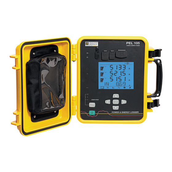
- Page 1 GB - User’s manual PEL 105 Power energy logger...
- Page 2 Thank you for purchasing a PEL 105 power and energy logger. For best results from your instrument: „ read these operating instructions carefully, „ comply with the precautions for use. WARNING, risk of DANGER! The operator must refer to these instructions whenever this danger symbol appears.
-
Page 3: Table Of Contents
CONTENTS 1. FIRST USE .....................................4 1.1. Delivery condition ................................4 1.2. Accessories .................................5 1.3. SPARE PARTS ................................5 2. PRESENTATION OF THE INSTRUMENT ..........................6 2.1. Description ...................................6 2.2. Front panel ..................................7 2.3. Terminal block ................................8 2.4. Installation of the coloured inserts ..........................8 2.5. -
Page 4: First Use
Set of inserts and rings used to identify the phases on the measurement leads and on the current sensors. 8GB SD card (in the instrument). SD card-USB adapter. Certificate of verification. Safety data sheet of the PEL 105. Getting started guide to the PEL 105. AmpFlex A196A tight current sensors. ®... -
Page 5: Accessories
1.2. ACCESSORIES MiniFlex MA193 250 mm ® MiniFlex MA193 350 mm ® MiniFlex MA196 350 mm tight ® MN93 clamp MN93A clamp C193 clamp PAC93 clamp E3N clamp BNC adapter for E3N clamp J93 clamp 5A adapter (three-phase) Essailec 5A adapter ®... -
Page 6: Presentation Of The Instrument
PEL: Power & Energy Logger (power and energy logger) The PEL 105 is a DC, single-phase, two-phase, and three-phase (wye and D) power and energy logger in a rugged sealed housing. The PEL has all power/energy recording functions needed for most of the world's 50Hz, 60Hz, 400Hz, and DC distribution net- works, with many connection possibilities to suit different installations. -
Page 7: Front Panel
(optional USB connector. LCD display unit. mains power unit). QR code. PEL 105 POWER & ENERGY LOGGER Selection key. Bag in which to stow Directional keypad: four naviga- the sealing plugs of tion keys and one validation key On / Off key. -
Page 8: Terminal Block
2.3. TERMINAL BLOCK 4 current inputs (specific 4-point connectors). 5 voltage inputs (safety connectors). VE/GND Figure 3 The plugs keep the terminals tight (IP67) when they are not in use. When you connect a current sensor or a voltage lead, screw it tight to keep the instrument tight. Stow the plugs in the bag attached to the cover of the instrument. -
Page 9: Functions Of The Keys
2.5. FUNCTIONS OF THE KEYS Description On / Off Key: Switches the instrument on or off. Remark: The instrument cannot be switched off when it is connected to mains (whether by the measurement inputs or by the mains power unit) or when recording is in progress or pending. Selection key: A long press activates or deactivates Wi-Fi or the Bluetooth link and starts or stops recording. -
Page 10: Indicators
The bottom and top strips provide the following indications: Icon Description Indicator of a reversal of phase order or a missing phase (displayed for three-phase distribution networks, and only in measurement mode; see the explanation below) Data available for recording. Indication of the power quadrant. -
Page 11: Memory Card
Indicators Colour and function Red indicator: Overshoot of the measurement range Indicator off: no overshoot on the inputs. Indicator blinking: overshoot on at least one input. Indicator lit: a lead is missing or connected to the wrong terminal. Green / red indicator: SD card Green indicator lit: the SD card is recognized and not locked. -
Page 12: Configuration
3. CONFIGURATION The PEL must be configured before any recording. The various steps in this configuration are: „ Set up the Wi-Fi link, the Bluetooth link, the USB link, or the Ethernet link. „ Choose the connection according to the type of distribution network. „... -
Page 13: Battery Charging
120 V ± 10 %, 60 Hz 230 V ± 10 %, 50 Hz „ Withdraw the elastomer cap that protects the power supply connector. PEL 105 POWER & ENERGY LOGGER „ Connect the mains power unit to the instru- ment and to mains. -
Page 14: Connection By Wi-Fi Or By The Bluetooth Link
If you release it while the indicator is lit, the Bluetooth link is activated or deactivated. „ PEL 105 POWER & ENERGY LOGGER Figure 9 If your computer does not generate Bluetooth, use a USB-Bluetooth adapter. If you have no driver for this peripheral, Windows installs one automatically. - Page 15 To enter the Configuration via the instrument mode, press the or key until the symbol is selected. The following screen is displayed: Figure 10 If the PEL is already being configured via the PEL Transfer software, it is impossible to enter the Configuration mode in the instrument.
- Page 16 3.5.2. CURRENT SENSORS Connect the current sensors to the instrument. The current sensors are automatically detected by the instrument. It looks at the L1 terminal. If there is nothing, it looks at the L2 terminal, or the L3 terminal. If the chosen network is not balanced, it also looks at the N terminal. Once the sensors have been recognized, the instrument displays their ratio.
- Page 17 Depending on the type of current sensor, MiniFlex /AmpFlex , MN clamp, or adapter unit, enter the nominal primary current. To ® ® do this, press the Enter key. Use the , , and keys to choose the current. „...
-
Page 18: Information
3.6. INFORMATION To enter the Information mode, press the or key until the symbol is selected. Use the and keys to scroll the information of the instrument: „ Type of network „ Nominal primary voltage „ Nominal secondary voltage „... - Page 19 „ Nominal primary current of the neutral (if a sensor is connected to the terminal) „ Aggregation period „ Date and time „ IP address (scrolling)
- Page 20 „ Wi-Fi address (scrolling) „ Software version number = software version of the DSP „ number = software version of the microprocessor „ Scrolling serial number (also on the QR code label glued to the „ inside of the cover of the PEL) After 3 minutes with no action on the Enter or Navigation key, the display returns to the measurement screen...
-
Page 21: Use
4. USE When the instrument has been configured, you can use it. 4.1. DISTRIBUTION NETWORKS AND CONNECTIONS OF THE PEL Start by connecting the current sensors and the voltage measurement leads to your installation according to the type of distribution network. - Page 22 4.1.3. THREE-PHASE 3-WIRE SUPPLY NETWORKS 4.1.3.1. Three-phase, 3-wire, (with 2 current sensors): 3P-3W „ Connect the VE/GND terminal to the earth. „ Connect the V1 terminal to the L1 phase. „ Connect the V2 terminal to the L2 phase. „ Connect the V3 terminal to the L3 phase. „...
- Page 23 4.1.3.4. Three-phase, 3-wire open (with 3 current sensors): 3P-3W03 „ Connect the VE/GND terminal to the earth. „ Connect the V1 terminal to the L1 phase. „ Connect the V2 terminal to the L2 phase. „ Connect the V3 terminal to the L3 phase. „...
- Page 24 4.1.3.7. Three-phase, 3-wire balanced (with 1 current sensor): 3P-3W „ Connect the VE/GND terminal to the earth. „ Connect the V1 terminal to the L1 phase. „ Connect the V2 terminal to the L2 phase. „ Connect the I3 current sensor to the L3 phase. Always check that the arrow of the current sensor points towards the load.
- Page 25 4.1.4.3. Three-phase, 4-wire, wye 2½-elements: 3P-4WY2 „ Connect the N terminal to the neutral. „ Connect the VE/GND terminal to the earth. „ Connect the V1 terminal to the L1 phase. „ Connect the V3 terminal to the L3 phase. „...
- Page 26 4.1.5.2. Three-phase, 4-wire, open : 3P-4WO „ Connect the N terminal to the neutral. „ Connect the VE/GND terminal to the earth. „ Connect the V1 terminal to the L1 phase. „ Connect the V2 terminal to the L2 phase. „...
-
Page 27: Recording
4.1.6.3. DC 4-wire: DC-4W „ Connect the N terminal to the common conductor. „ Connect the VE/GND terminal to the earth. „ Connect the V1 terminal to the +1 conductor. „ Connect the V2 terminal to the +2 conductor. „ Connect the V3 terminal to the +3 conductor. „... - Page 28 4.3.1. MEASUREMENT MODE The display depends on the network configured. Press the key to go from one screen to the next. Single-phase, 2-wire (1P-2W) ϕ (I tan ϕ...
- Page 29 Two-phase, 3-wire (2P-3W) ϕ (I ϕ (V ϕ (I ϕ (I tan ϕ...
- Page 30 Three-phase, 3-wire, unbalanced (3P-3WD2, 3P-3WD3, 3P-3WO2, 3P-3WO3, 3P-3WY2, 3P-3WY3) ϕ (I ϕ (I ϕ (I ϕ (U ϕ (U ϕ (U ϕ (I ϕ (I ϕ (I tan ϕ...
- Page 31 Three-phase, 3-wire ∆, balanced (3P-3W∆b) ϕ (I tan ϕ...
- Page 32 Three-phase, 4-wire, unbalanced (3P-4WY, 3P-4WY2, 3P-4WD, 3P-4WOD) ϕ (I ϕ (I ϕ (I ϕ (V ϕ (V ϕ (V ϕ (U ϕ (U ϕ (U ϕ (I ϕ (I ϕ (I *: For 3P-4WD and 3P-4WOD networks...
- Page 33 tan ϕ Three-phase, 4-wire, wye, balanced (3P-4WYb)
- Page 34 ϕ (I tan ϕ DC 2-wire, (dC-2W) DC 3-wire, (dC-3W)
- Page 35 DC 4-wire, (dC-4W)
- Page 36 4.3.2. ENERGY MODE The powers displayed are the total powers. The energy depends on the duration; typically it is available at the end of 10 or 15 minutes or at the end of the aggregation period. Press the Enter key for more than 2 seconds to obtain the powers by quadrant (IEC 62053-23). The display unit indicates PArt to specify that the values are partial.
- Page 37 Ep-: Total active energy delivered (by the source) in kWh Eq1: Reactive energy consumed (by the load) in the inductive quadrant (quadrant 1) in kvarh. Eq2: Reactive energy delivered (by the source) in the capacitive quadrant (quadrant 2) in kvarh. Eq3: Reactive energy delivered (by the source) in the inductive quadrant (quadrant 3) in kvarh.
- Page 38 Eq4: Reactive energy consumed (by the load) in the capacitive quadrant (quadrant 4) in kvarh. Es+: Total apparent energy consumed (by the load) in kVAh Es-: Total apparent energy delivered (by the source) in kVAh DC networks Ep+: Total active energy consumed (by the load) in kWh...
- Page 39 Ep-: Total active energy delivered (by the source) in kWh 4.3.3. HARMONICS MODE The display depends on the network configured. The harmonics display is not available for DC networks. The display unit indicates "No THD in DC mode". Single-phase, 2-wire (1P-2W) I_THD V_THD Two-phase, 3-wire (1P-3W)
- Page 40 _THD _THD _THD Three-phase, 3-wire, unbalanced (3P-3WD2, 3P-3WD3, 3P-3WO2, 3P-3WO3, 3P-3WY2, 3P-3WY3) _THD _THD _THD _THD _THD _THD Three-phase, 3-wire ∆, balanced (3P-3W∆b) _THD = I _THD _THD = I _THD _THD...
- Page 41 _THD _THD = U _THD _THD = U _THD Three-phase, 4-wire, unbalanced (3P-4WY, 3P-4WY2, 3P-4WD, 3P-4WOD) _THD _THD _THD _THD _THD _THD _THD Three-phase, 4-wire, wye, balanced (3P-4WYb) _THD _THD _THD...
- Page 42 _THD _THD _THD 4.3.4. MAXIMUM MODE Depending on the option selected in PEL Transfer, these may be the maximum aggregated values of the recording in progress or of the last record, or the maximum aggregated values since the last reset. The maximum display is not available for DC networks.
- Page 43 Two-phase, 3-wire (1P-3W)
- Page 44 Three-phase, 3-wire (3P-3WD2, 3P-3WD3, 3P-3WO2, 3P-3WO3, 3P-3WY2, 3P-3WY3, 3P-3W∆b)
- Page 45 Three-phase, 4-wire (3P-4WY, 3P-4WY2, 3P-4WD, 3P-4WOD), 3P-4WYb) For the balanced network (3p-4WYb), I is not displayed.
-
Page 47: Pel Transfer Software
5. PEL TRANSFER SOFTWARE 5.1. FUNCTIONS PEL transfer software is used to: „ Connect the instrument to the PC by Wi-Fi, Bluetooth, USB, or Ethernet. „ assign a name to the instrument, choose the brightness and contrast of the display unit, disable the Selection key of the instrument, set the date and time, format the SD card, etc. - Page 48 A warning message like the one shown below appears. Click on OK. Figure 33 Installing the driver may take some time. Windows may even indicate that the program is no longer respond- ing, even though it is in fact running. Wait for it to terminate. When the driver has been installed, the Installation succeeded dialogue box is displayed.
-
Page 49: Technical Characteristics
6. TECHNICAL CHARACTERISTICS Uncertainties are expressed as a percentage (%) of the reading (R) and number of display points (pt): ± (a%R + b pt) 6.1. REFERENCE CONDITIONS Parameter Reference conditions Ambient temperature 23 ± 2 °C Relative humidity 45% RH to 75% RH Voltage No DC component in the AC, no AC component in the DC (<... - Page 50 6.2.3. INTRINSIC UNCERTAINTY (NOT COUNTING THE CURRENT SENSORS) The uncertainties in the tables below are given for the "1s" and aggregated values. For the "200ms" measurements, the uncertain- ties must be doubled 6.2.3.1. Specifications at 50/60Hz Quantities Measurement range Intrinsic uncertainty Frequency (f) [42.5;...
- Page 51 Quantities Measurement range Intrinsic uncertainty Apparent energy (Es) V = [100V; 1,000V] ± 0.5% R kVAh I = [5% Inom; 120% Inom] PF = 1 V = [100V; 1,000V] ± 1% R I = [10 % Inom; 120% Inom] Table 7 Inom is the measured current when the output from the current sensor is 1V.
- Page 52 6.2.3.3. Specifications in DC Quantities Measurement range Typical intrinsic uncertainty Voltage (V) V = [100V; 600 V] ± 0.2% R ± 0.2 V Neutral-earth voltage (V V = [2 V; 600 V] ± 0.2% R ± 0.2 V Current (I) I = [5% Inom;...
- Page 53 6.2.4.2. Characteristics The measurement ranges are those of the current sensors. These are sometimes different from those of the PEL. Refer to the user manual provided with the current sensor. a) AmpFlex A196A or AmpFlex A193 ® ® „ Press on both sides of the opening device to unlock the flexible coil. Open it, then place it around the conductor carrying the current to be measured (only one conductor per coil).
- Page 54 b) MiniFlex MA193 and MA196 ® MiniFlex MA193 and MA196 ® 100 / 400 / 2,000 / 10,000Aac (provided that the conductor can be Nominal range clamped) Measurement range 200mA to 2,400A Length = 250 mm; Ø = 70 mm Maximum clamping diameter Length = 350 mm;...
- Page 55 e) PMN93 clamp MN93 clamp Nominal range 200 A for f ≤ 10 kHz Measurement range 0.5 at 240A max (I >200A non-permanent) Maximum clamping diameter 20 mm Influence of the position of the con- < 0.5%, at 50/60Hz ductor in the clamp Influence of an adjacent conductor ≤...
- Page 56 h) J93 clamps J93 clamps Nominal range 3,500A , 5,000A Measurement range 50 - 3,500A ; 50 - 5,000A Maximum clamping diameter 72 mm Influence of the position of the < ± 2% conductor in the clamp Influence of an adjacent conductor >...
- Page 57 6.2.4.3. Intrinsic uncertainty The intrinsic uncertainties of the current measurements and of the phase must be added to the intrinsic uncertainties of the instrument for the quantity concerned: power, energies, power factors, tan Φ, etc. The following characteristics are given for the reference conditions of the current sensors. Characteristics of the current sensors (output 1V at Inom) Typical Intrinsic...
-
Page 58: Communication
Characteristics of the AmpFlex and MiniFlex ® ® Intrinsic Intrinsic Intrinsic Typical uncer- Current Current uncertainty I nominal uncertainty at 50/ uncertainty tainty on ϕ at sensor (RMS or DC) on ϕ 60Hz at 400Hz 400 Hz at 50/60 Hz [200 mA;... -
Page 59: Power Supply
6.4. POWER SUPPLY Mains supply „ Range of operation: 100V to 1,000V for a frequency from 42.5 to 69Hz 100V to 600 V for a frequency from 340 to 460 Hz 140V to 1,000V in DC „ Maximum power: 30VA Battery „... -
Page 60: Electrical Safety
„ Degrees of protection per IEC 60529 IP 67 when the cover of the instrument is closed, the voltage leads are screwed, and the leads of the AmpFlex A196A ® „ are screwed. IP 67 when the cover of the instrument is closed and the plugs on the terminals are in place. „... -
Page 61: Maintenance
7.3. UPDATING THE SOFTWARE With a view to providing, at all times, the best possible service in terms of performance and technical upgrades, Chauvin Arnoux invites you to update the embedded software of the device (firmware) and the application software (PEL Transfer). - Page 62 7.3.2. UPDATING PEL TRANSFER When started up, PEL Transfer checks that you have the latest version. If not, it invites you to upgrade. You can also download upgrades from our site: www.chauvin-arnoux.com Go to “Support”, then search on “PEL105”.
-
Page 63: Warranty
8. WARRANTY Except as otherwise stated, our warranty is valid for 24 months starting from the date on which the equipment was sold. Extract from our General Conditions of Sale provided on request. The warranty does not apply in the following cases: „... -
Page 64: Appendix
9. APPENDIX 9.1. MEASUREMENTS 9.1.1. DEFINITION The calculations are performed in accordance with standards IEC 61557-12, IEC 61000-4-30, and IEEE 1459. Geometrical representation of the active and reactive powers: Load Source Active power Active power supplied consumed Reactive power consumed φ... - Page 65 9.1.2.2. Locking of the sampling frequency „ As default, the sampling frequency is locked to V1. „ If V1 is missing, the instrument attempts to lock to V2, then to V3, I1, I2, and I3. 9.1.2.3. AC/DC The PEL makes AC and DC measurements for AC and DC distribution networks. AC or DC is selected by the user. The AC + DC values are available with PEL Transfer.
-
Page 66: Measurement Formulas
9.2. MEASUREMENT FORMULAS Most of the formulas are taken from standard IEEE 1459. The PEL measures or calculates the values below for one cycle (128 samples per period from 16 to 400Hz. These values are not accessible to the user. The PEL then calculates a value aggregated over 10 cycles (50Hz), 12 cycles (60Hz), or 80 cycles (400Hz) ("200ms"... - Page 67 Quantities Formulas Remarks × AC fundamental apparent power − − L = 1, 2 or 3 PF = AC power factor (PF L = 1, 2 or 3 − AC active power unbalance (Pu) − AC harmonic active powers (P ϕ...
- Page 68 I1, I2, I3 are the currents flowing in the phase conductors of the installation measured. is the current flowing in the neutral conductor of the installation measured. The lower-case i1, i2, i3 designate the sampled values. For some quantities linked to the powers, the "generated" and "consumed" quantities are counted separately for the values ag- gregated from the "1s"...
- Page 69 Quantities Formulas Remarks Φ − Φ (Φ AC generated Tan − − DC measurements ∑ × DC consumed active power (P L = 1, 2, 3 or T L+dc ∑ − × × − − DC generated active power (P L = 1, 2, 3 or T L-dc AC+DC measurements...
-
Page 70: Electrical Networks Allowed
9.3. ELECTRICAL NETWORKS ALLOWED The following types of distribution network are managed: Distribution Reference Phase Abbreviation Remarks network order diagram Single-phase The voltage is measured between L1 and N. (single-phase 1P- 2W See § 4.1.1. The current is measured on the L1 conductor. 2-wire) Two-phase The voltage is measured between L1, L2 and N. -
Page 71: Quantity According To The Distribution Network
Distribution Reference Phase Abbreviation Remarks network order diagram The power measurement is based on the three-wattmeter method with neutral, but no power information is available Three-phase, 3P-4WD See § 4.1.5.1. for the individual phases. 4-wire D The voltage is measured between L1, L2 and L3. The current is measured on the L1, L2 and L3 conductors. - Page 72 3P-3W∆2 3P-3W∆3 3P-4W∆ Quantities 1P-2W 1P-3W 3P-3WO2 3P-3WO3 3P-3W∆B 3P-4WY 3P-4WYB 3P-4WY2 DC-2W DC-3W DC-4W 3P-4WO∆ 3P-3WY2 3P-3WY3 AC + AC + ...
- Page 73 3P-3W∆2 3P-3W∆3 3P-4W∆ Quantities 1P-2W 1P-3W 3P-3WO2 3P-3WO3 3P-3W∆B 3P-4WY 3P-4WYB 3P-4WY2 DC-2W DC-3W DC-4W 3P-4WO∆ 3P-3WY2 3P-3WY3 (10) ...
- Page 74 3P-3W∆2 3P-3W∆3 3P-4W∆ Quantities 1P-2W 1P-3W 3P-3WO2 3P-3WO3 3P-3W∆B 3P-4WY 3P-4WYB 3P-4WY2 DC-2W DC-3W DC-4W 3P-4WO∆ 3P-3WY2 3P-3WY3 -THD -THD (10) -THD -THD ...
-
Page 75: Glossary
9.5. GLOSSARY ϕ Phase shift of the phase-neutral voltage with respect to the phase-neutral current. Inductive phase shift. Capacitive phase shift. ° Degree. Percentage. Ampere (unit of current). AC component (current or voltage). Aggregation Various means defined in § 9.2. Crest factor of the current or voltage: ratio of the crest (peak) value of a signal to the RMS value. - Page 76 RMS voltage (L = 1, 2, or 3) Value or percentage of phase-neutral voltage of the n harmonic (L = 1, 2 or 3). L-Hn Unit of active power (Watt). Unit of active energy (Watt x hour). Prefixes of the units of the international system (SI) Prefix Symbol Multiplies by...
- Page 78 FRANCE INTERNATIONAL Chauvin Arnoux Group Chauvin Arnoux Group 190, rue Championnet Tél : +33 1 44 85 44 38 75876 PARIS Cedex 18 Fax : +33 1 46 27 95 69 Tél : +33 1 44 85 44 85 Our international contacts Fax : +33 1 46 27 73 89 info@chauvin-arnoux.com...
Need help?
Do you have a question about the PEL 105 and is the answer not in the manual?
Questions and answers