Table of Contents
Advertisement
Quick Links
Advertisement
Table of Contents

Related Manuals for Chauvin Arnoux ULYS MCM


Summary of Contents for Chauvin Arnoux ULYS MCM
-
Page 1: Ulys Mcm
EN - ULYS MCM User Manual ULYS MCM Multi-channel power meter... - Page 2 You have just acquired the ULYS MCM, a three-phase digital power meter, and we thank you for your confidence. To get the best service from your device: Read this user manual carefully before installing and using the device; Observe the precautions for use.
-
Page 3: Precautions For Use
PRECAUTIONS FOR USE This device complies with the safety standard IEC 61010-2-030, for voltages up to 300 V in overvoltage category II and for voltages up to 600 V in measurement category III. The current sensors comply with IEC 61010-2-032, for voltages up to 1000 V in measurement category III. - Page 4 CLEANING CAUTION Disconnect all connections to the unit. Wipe with a soft, clean and dry cloth. Do not use alcohol, solvents or hydrocarbons. For current sensors: Make sure that no foreign objects interfere with the operation of the sensor's latching device. Keep the air gaps of the current sensors perfectly clean.
-
Page 5: Table Of Contents
Dimensions of the ULYS MCM D remote screen ....................23 3.1.4 Installation conditions and methods ........................23 3.1.5 Description .................................24 Behaviour of the ULYS MCM D and layout of the menus ..................25 3.2.1 Uses of the remote screen ..........................25 3.2.2 Menu Layout ..............................25 3.2.2.1 Screen layout ...............................25... - Page 6 Description of the drop-down menus .........................35 4.2.2 Description of tree options ..........................35 4.2.3 Description of context menu options ........................36 Connecting TO and disconnecting FROM the ULYS MCM ..................36 4.3.1 Prerequisites ..............................36 4.3.2 Operating mode ..............................37 Programming THE ULYS MCM ..........................38 4.4.1...
-
Page 7: Equipment Description
They also allow the user to be isolated from dangerous voltages in the circuit. You must use current transformers that are approved and/or compatible for ULYS MCM and conforming to IEC standards. In order to help you choose the product references, you will need to answer the following questions:... -
Page 8: Introduction
2.1.3 INTRODUCTION Installed inside an electrical cabinet or panel, the ULYS MCM allows you to measure and monitor several electrical loads within your production lines or the equipment in your installations for detailed analysis and diagnosis of your energy consumption. -
Page 9: Technical Specifications
2.1.5 TECHNICAL SPECIFICATIONS Designation Specification Electrical system 1P2F, 3P3F, 3P4F Voltage (Umin - Umax) 43-690 V~ between phases Voltage (Vmin - Vmax) 25-400 V~ between phase and neutral Measurement category 600 V Cat III Nominal Frequency 45-65 Hz input specifications Current 0-333 mV (max 0.5 V p-p) | Impedance: 20 kΩ... -
Page 10: Measurement Performance Characteristics
2.1.7 MEASUREMENT PERFORMANCE CHARACTERISTICS The table below shows the accuracy class of the ULYS MCM's electrical measurements according to the sensors to which it can be connected: ULYS MCM Measurement Standard ULYS MCM MF300/MF3000 Measurements of active power (P) IEC 61557-12: 2018... -
Page 11: Electrical Values
2.1.8 ELECTRICAL VALUES The above table shows the measured electrical values and their resolution: Designation Unit Value Remark Phase voltage 0.00 – 9,999,999.99 Line voltage 0.00 – 9,999,999.99 Line current 0.00 – 9,999,999.99 Active power ±0 – 999,999,999 Reactive power ±0 –... -
Page 12: Mechanical Installation
INSTALLATION PROCEDURE DANGER The ULYS MCM must be installed inside an electrical cabinet or switchboard to prevent access after installation. It has been designed for indoor use, so care must be taken not to expose it directly to the outside environment. -
Page 13: Electrical Installation
RUN / STAT / Comm Comm: normal communication (LED flashing in normal status) RS232 port Communication with the computer or the remote display ULYS MCM D 2.3.5.3 RS485 port RS485 port for connecting the computer or an external PLC 2.3.5.2... -
Page 14: Auxiliary Power Supply To Appliance
The ULYS MCM can be supplied with an AC voltage from 100 to 240 V~, and the electrical connection must be made as shown below: Pin no. -
Page 15: Current Measurement Inputs
The ULYS MCM can be connected to different types of current sensors (see section 0.2). The ULYS MCM will have to be configured from the ULYS MCM D remote screen or from the Ulys MCM Utility software to select the type of sensor for each channel. -
Page 16: 2.3.2.3.2 Current Sensors For Use With Ulys Mcm
2.3.2.3.2 Current sensors for use with ULYS MCM Openable flexible current sensors (Rogowski coil) type MF300 and MF3000: Press the yellow opening device to open the flexible torus. Open it and place it around the conductor through which the current to be measured flows (only one conductor in the sensor). - Page 17 MECHANICAL CHARACTERISTICS MF300 MF3000 Height: 12 mm Height: 12 mm MF300: length = 250 mm; Ø = 70 mm Clamping diameter MF3000: length = 350 mm; Ø = 100 mm Length of the connecting cable 1;5 metre (between the output connector and the reel) Degree of protection provided by the envelopes IP50 according to IEC 60529 Degree of protection against mechanical impact...
- Page 18 Close the CT primary, making sure that it is clipped in place. Make sure that the direction of the arrow on the side of the CT is pointing in the direction of the current flow in the cable. GENERAL CHARACTERISTICS TCC V 105: 5 A TCC V 161: 100 A Rated current (In)
-
Page 19: Status Leds
Discrete input terminal: 80-250 V~ status change input voltage required. 2.3.5 PORTS To exchange with a PLC or a SCADA PC, the ULYS MCM can communicate on Ethernet or RS485 media. For more details, please refer to the communication table (page 47). -
Page 20: Ethernet Port (Lan)
Communication settings can be made using the ULYS MCM D remote display. 2.3.5.3 PDM ports (RS-232) This port allows the connection of the ULYS MCM D remote display to display measurement data and setting values. Serial communication type: RS-232C Binary structure: 8 bits, 1 start bit, 1stop bit... -
Page 21: Temperature Sensor
4~20 mA 3: - Temperature settings can be made using the Temp Ai Type option of the Ulys MCM Utility software. For details, refer to "4.4.1.1 Description of the CONFIG settings" on page 39. When using the NTC sensor, the following characteristics must be observed:... -
Page 22: Ulys Mcm D
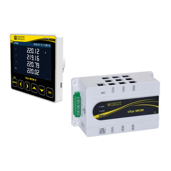
3 ULYS MCM D DESCRIPTION OF THE ULYS MCM D The ULYS MCM can be associated with a ULYS MCM D remote display for the display of all measurements and the product configuration. It is directly self-powered by the ULYS MCM. -
Page 23: Dimensions Of The Ulys Mcm D Remote Screen
3.1.4 INSTALLATION CONDITIONS AND METHODS ULYS MCM D must be installed exclusively indoors. Avoid environments with high temperatures and the presence of strong electric fields. Please refer to the diagram below when mounting the remote display on an electrical cabinet. -
Page 24: Description
3.1.5 DESCRIPTION The ULYS MCM D remote display is composed of the following elements: Designation Description " LCD screen TFT colour LCD Status LED Operating status display Keys Tactile operating buttons Mounting clip For fixing to an electrical cabinet Communication port... -
Page 25: Behaviour Of The Ulys Mcm D And Layout Of The Menus
Level / Swell cycle Overvoltage indication 3.2.2 MENU LAYOUT The menus on the ULYS MCM D remote screen allow the different measured values to be viewed and the product to be configured. 3.2.2.1 Screen layout When communication is established with the ULYS MCM, the screen below appears before displaying the menu screen. -
Page 26: Layout Of The Display And Configuration Menus
ROM Save Common Setup: configuration of parameters common to all measurement channels. Branch Setup: configuration of the channel-specific parameters. ROM Save: save and transfer the configuration to the ULYS MCM. To be carried out each time a modification is made. -
Page 27: Viewing Menus
VIEWING MENUS 3.3.1 COMMON MENU Press the MENU button to access the menu screen, then press the Down button to select the Common menu and press OK to confirm. The Common menu includes all the sizes that are not specific to each channel. It displays measured values such as phase and line voltages, frequency, voltage unbalance, temperature and event status. -
Page 28: Branch Menu
3.3.2 BRANCH MENU Press the MENU button to access the menu screen, then press the Down button to select the Branch menu and press OK to confirm. The Branch menu gives all the quantities specific to each measurement channel. All channel values are grouped together on the same screen. There are as many screens as there are channels defined on the device. -
Page 29: Category Menu
Designation Description Voltage Displays phase voltage measurements Line Voltage Displays line voltage measurements Current Displays the intensity of the electric current Active Power Displays active power Reactive Power Displays the reactive power Apparent Power Displays apparent power Power Factor Displays the power factor Power THD Displays the total harmonic distortion I-Unbalance... -
Page 30: Configuration Menus
Enter the desired value using the Up or Down key and press OK to confirm. Press the MENU button to cancel. Then select the ROM Save menu and press OK if you wish to permanently transfer the new settings to the ULYS MCM. - Page 31 Designation Description Display / Change ID (modbus address) Port Check / Change Ethernet port Check / Change IP address Subnet mask Check / Change subnet mask Gateway Checking / Changing the gateway MAC addr. Show MAC address RS485 Check / Change network type Check / Change the speed of the RS485 network (9600, 19200, Baudrate 38400, 57600, 115200)
-
Page 32: Branch Setup Menu
Select Save to save and return to the previous menu. Select Cancel to return to the setting change page. Then select the ROM Save menu and press OK if you wish to permanently transfer the new settings to the ULYS MCM. -
Page 33: Rom Save Menu
The ROM Save menu is used to permanently save the changed values. CAUTION If you do not execute the ROM Save function, the previous power supply values will be restored when the ULYS MCM D is restarted. After the settings are completed, be sure to execute this function to save the final settings. -
Page 34: Ulys Mcm Utility
4 ULYS MCM UTILITY QUICK OVERVIEW Ulys MCM Utility is the real-time configuration and visualisation software for the ULYS MCM. It allows the user to configure the settings and easily check the data for each load. It is not designed to collect data from your system, but you can develop your own management software from our mapping table provided in Chapter 6. -
Page 35: Description Of The Drop-Down Menus
The communication logs from the Communication Frame option can be retrieved in the following sub-folder: \Ulys\Log (.txt file generated at the current date). 4.2.2 DESCRIPTION OF TREE OPTIONS The options in the tree structure of the left pane of the Ulys MCM Utility software window are used to configure the ULYS MCM. Option Description Ulys MCM (Device-1) Type of equipment installed, and name given to the device Monitor the data measured by the ULYS MCM per feeder. -
Page 36: Description Of Context Menu Options
4.2.3 DESCRIPTION OF CONTEXT MENU OPTIONS If you right-click on the name of your ULYS MCM in the tree view, a context menu appears. It contains various options for managing your equipment. Option Description Establish a connection between the ULYS MCM and the PC (the next Connect time the software is started, the connection is automatic). -
Page 37: Operating Mode
CAUTION To connect to the product via the LAN, the IP address of the PC or PLC must be compatible with that of the ULYS MCM. 4.3.2 OPERATING MODE To establish a LAN connection, set the IP address of the PC to "192.168.0.xxx" (xxx other than 001). -
Page 38: Programming The Ulys Mcm
③ Blinking green Grey PROGRAMMING THE ULYS MCM The ULYS MCM is programmed using the Setup option in the tree view of the Ulys MCM Utility software. When you double-click this option, the right-hand pane displays the information described below. -
Page 39: Description Of The Main Setting Tab
Status Change: on status change. o DI Input: Detection of a change of state. o Comm: via communication (see section 5.1 Mapping of the ULYS MCM Modus values). PF Sign: select the power factor calculation reference frame (IEC or IEEE). -
Page 40: Description Of Etc Settings
4.4.1.2 Description of ETC settings Settings such as alarms, voltage sags and swells are grouped together in the ETC section. Temp Alarm: indicate the temperature value to trigger an alarm. If the temperature is higher than this set value, the digital output DO is activated; if the temperature is lower, the digital output DO is deactivated (if the DO Alarm parameter is set to "temp alarm "... - Page 41 Occurrence and reset of a voltage sag event Occurrence and reset of a swell event...
- Page 42 “Demand total prediction” value in W Alarm Level 3: 3,000 W Alarm Level 2: 2,400 W Alarm Level 1: 1,200 W End of the integration period - Reset of the Start of the value "Demand total integration period prediction in W". Closed Status of output relay DO Open...
-
Page 43: Descriptions Of The Communication Settings
485 baudrate: Select the speed of the RS485 network (9600, 19200, 38400, 57600), 115200). TCP port: Specify the TCP port number. IP Address: Specify the IP address of the ULYS MCM. Gateway: Specify the IP address of the gateway. Subnet: Specify the mask IP address of the subnet. - Page 44 Option Description Number Displays the channel number Wire Display / Change the type of wiring (3P4W, 3P3W or 1P3W) Display / Change the type of current sensor (Rogowski coil or CLAMP CT Type TC (mV)) Display / Change the main / secondary value of the current transformer CT 2nd connected to the feeder Note : this value must not be changed when using Rogowski coils.
-
Page 45: Visualisation Of Measured Values
VISUALISATION OF MEASURED VALUES The Status All, Real Time Trend and Historical Trend options in the tree view of the Ulys MCM Utility software allow you to view the various values of all the feeders. 4.5.1 DESCRIPTION OF THE STATUS ALL OPTION When you double-click the Status All option, all available information is displayed on the screen-below. - Page 46 You can also analyse the historical trend of certain measured values. Double-click the Historical Trend option to display the window below. Select the time range to be analyzed using the Date and Time drop-down lists, and then choose the graph style using the Trend Style drop-down list.
-
Page 47: Modbus Mapping
ULYS MCM MODBUS VALUE MAPPING Type of communication: o Two types of remote communication can be used on the ULYS MCM: conventional Modbus/RTU on RS-485 bus or/and Modbus/TCP on TCP/IP network. o Both types of communication can be used simultaneously. -
Page 48: Status Words
STATUS WORDS 5.2.1 TABLE 1 Voltage sag and overvoltage: T-Sag, S-Sag, R-Sag, T-Swell, S-Swell, R-Swell o Refer to paragraph 4.4.1.2 " Description of ETC settings " for the operation of these variables. R, S, T correspond respectively to the voltages phase 1 (V1), phase 2 (V2), phase 3 (V3). The value 0 corresponds to the "non-alarm"... -
Page 49: Voltage Sag (T-Sag, S-Sag, R-Sag) And Swell (T-Swell, S-Swell, R-Swell) Variables
5.2.2 VOLTAGE SAG (T-SAG, S-SAG, R-SAG) AND SWELL (T-SWELL, S-SWELL, R-SWELL) VARIABLES The variables associated with the operation of voltage sag and swell events are as follows: o Values of the thresholds programmed on voltage sags (Sag Level) and swells (Swell Level) (see paragraph 4.4.1.2 - Description of ETC settings). o T-Sag, S-Sag, R-Sag, T-Swell, S-Swell, R-Swell (see paragraph 5.2.1 - Table 1) o Date and Time for voltage sags: addresses 5C to 61 (Hexa)in the reduced measurement table or 958 to 95D (Hexa) in the full measurement table. -
Page 50: Command Words
COMMAND WORDS "Demand Reset”: address x0120 o Reset average values (Demand) o Values updated every second in the mapping... -
Page 51: Types Of Mapping Variables
TYPES OF MAPPING VARIABLES... -
Page 52: Mapping Of The Modbus Values Of Ulys Mcm
MAPPING OF THE MODBUS VALUES OF ULYS MCM The data format for each byte in RTU mode: Coding System: 8-bit per byte Data Format: 4 bytes (2registers) per parameter Most significant register first (Default) Error Check Field: 2 byte Cyclical Redundancy Check (CRC) - Page 53 The data coding information: All data values are transferred as 32 bit IEEE754 floating point numbers, each value is transferred using two Modbus Protocol 16 bit registers. Bytes arrangement is big-endian (4-3-2-1). All registers read requests must specify an even number of registers. The table below is an extract from the device mapping.
-
Page 67: Warranty, Responsibility And Intellectual Property
First edition, June 2020. END-OF-LIFE EQUIPMENT ULYS MCM is a trademark registered by CAE. END OF LIFE OF THE DEVICES The products which we sell do not fall within the scope of Decree No. 2005-829 relating to the construction of electrical and electronic equipment and the disposal of waste arising from this equipment. - Page 68 Chauvin Arnoux Energy Antony II high-tech park 16, rue Georges Besse - Silic 44 92160 ANTONY Phone: +33 1 75 60 10 30 Fax: +33 1 46 66 62 54 E-mail: CAEnergy@chauvin-arnoux.com https://www.chauvin-arnoux-energy.com/fr...
Need help?
Do you have a question about the ULYS MCM and is the answer not in the manual?
Questions and answers