Table of Contents
Advertisement
Quick Links
Advertisement
Table of Contents

Subscribe to Our Youtube Channel
Related Manuals for Chauvin Arnoux PEL 112


Summary of Contents for Chauvin Arnoux PEL 112
- Page 1 EN - User’s manual PEL 112 PEL 113 Power & Energy Logger...
- Page 2 Thank you for purchasing a Power & Energy Logger PEL112 or PEL113. To obtain the best service from your unit: ■ read these operating instructions carefully, ■ comply with the precautions for use. WARNING, risk of DANGER! The operator must refer to these instructions whenever this danger symbol appears. WARNING! Risk of electric shock.
-
Page 3: Table Of Contents
CONTENTS 1. GETTING STARTED ................................6 1.1. Delivery condition ................................6 1.2. Accessories .................................7 1.3. Spare parts ..................................7 1.4. Charging the battery ..............................7 2. PRODUCT FEATURES ................................8 2.1. Description ...................................8 2.2. PEL112 ..................................9 2.3. PEL113 ..................................10 2.4. Back Panel Features ..............................11 2.5. - Page 4 Definition of measurement categories ■ Measurement category IV (CAT IV) corresponds to measurements taken at the source of low-voltage installations. Example: power feeders, meters and protection devices. ■ Measurement category III (CAT III) corresponds to measurements on building installations. Example: distribution panel, circuit-breakers, machines or fixed industrial devices. ■...
- Page 5 PRECAUTIONS FOR USE This instrument complies with safety standard IEC/EN 61010-2-030 or BS EN 61010-2-030 and the leads comply with IEC/EN 61010-031 or BS EN 61010-031, for voltages of 1000 V in measurement category III or 600 V in measurement category IV. Failure to observe the safety instructions may result in electric shock, fire, explosion, and destruction of the instrument and of the installations.
-
Page 6: Getting Started
1. GETTING STARTED 1.1. DELIVERY CONDITION ⑤ ① ② ③ ④ 1000V CAT III 600V CAT IV ⑦ ⑧ POWER & ENERGY LOGGER ⑥ ⑨ START/STOP ⑩ ⑪ ⑫ ATTESTATION DE VERIFICATION CHECKING ATTESTATION 190, rue Championnet 75876 PARIS Cedex 18 Numéro de l'appareil : FRANCE Equipment number... -
Page 7: Accessories
1.2. ACCESSORIES ■ MiniFlex MA194 250 mm ■ MiniFlex MA194 350 mm ■ MiniFlex MA194 1000 mm ■ MN93 clamp The weight exerted by the measuring leads may cause the mag- ■ MN93A clamp netic test probes to come loose. We advise you to support them ■... -
Page 8: Product Features
2. PRODUCT FEATURES 2.1. DESCRIPTION PEL: Power & Energy Logger The PEL112 and PEL113 are simple-to-use single-, dual-, and three-phase (Y, Δ) Power & Energy Loggers. The PEL offers all necessary functions for Power/Energy data logging for most 50 Hz, 60 Hz, 400 Hz and DC distribution systems worldwide, with many connection possibilities. -
Page 9: Pel112
2.2. PEL112 Measurement terminals. 1000V CAT III 600V CAT IV PEL 112 POWER & ENERGY LOGGER Rigid molded elastomer casing. 9 LEDs for status information. POWER & ENERGY LOGGER START/STOP ON/OFF key. Control key. Mains connector. USB and Ethernet connectors, SD memory card slot and connector caps. -
Page 10: Pel113
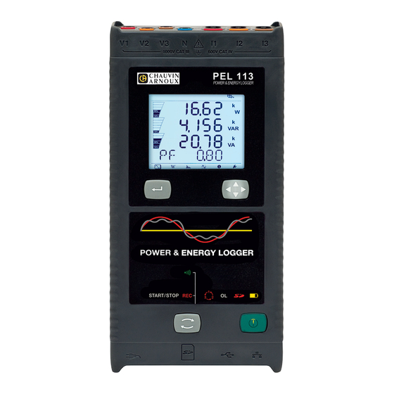
2.3. PEL113 Measurement terminals. 1000V CAT III 600V CAT IV LCD display unit. PEL 113 POWER & ENERGY LOGGER Rigid molded elastomer casing. Enter key. Navigation key. 9 LEDs for status information. POWER & ENERGY LOGGER START/STOP ON/OFF key. Control key. USB and Ethernet connectors, SD memory Mains connector. -
Page 11: Back Panel Features
2.4. BACK PANEL FEATURES 6 recessed Torx screws (for ® 4 magnets (molded into factory service use only). the rubber casing). Figure 5 2.5. TERMINAL BLOCK Voltage input terminals Current input terminals (safety banana plug inputs). (specific four-point jacks). The small holes (• •) are for the color- coded inserts used to identify the current and voltage inputs. -
Page 12: Installation Of The Colour-Coded Markers
2.6. INSTALLATION OF THE COLOUR-CODED MARKERS For multiple-phase measurements, start by marking the accessories and terminals with the colour-coded ID markers supplied with the device; a different colour for each terminal. ■ Detach the appropriate inserts and place them in the holes under the terminals (larger inserts for current terminals, smaller inserts for voltage terminals). -
Page 13: Key Functions
2.9. KEY FUNCTIONS Description ON/OFF key Turns the instrument ON or OFF. Note: The instrument cannot be turned OFF while connected to an AC outlet or if a recording is in progress. Control key: A long press activates or deactivates the Wi-Fi link and starts or stops recording. Enter key (PEL113) In the configuration mode, serves to select a parameter to be modified. - Page 14 The top and bottom bars indicate the following: Icon Description Phase Sequence reversal or missing phase indicator (displayed only in Measurement Mode, see explanations below) Data are available for recording (non-display indicates possible internal problem) Indication of the power quadrant (see §9.1) Measurement Mode (Real Time values) (see §4.3.1) Power and Energy Mode (see §4.3.2) Harmonics Mode (see §4.3.3)
-
Page 15: Led
2.12. LED LED & Colour Description Recording Status Indicator off: no recording programmed or in progress Red LED Indicator blinking: recording programmed Indicator on: recording in progress Wi-Fi LED off: Wi-Fi link off (disabled) LED on: Wi-Fi link enabled but not transmitting Green LED LED blinking: Wi-Fi link enabled and transmitting Phase order... -
Page 16: Operation
3. OPERATION The PEL must be configured before any recording. The various steps in this configuration are: ■ Set up the USB link, the Ethernet link or the Wi-Fi link. ■ Choose the connection according to the type of distribution network. ■... -
Page 17: Connection By Wi-Fi
1000V CAT III 600V CAT IV 1000V CAT III 600V CAT IV POWER & ENERGY LOGGER POWER & ENERGY LOGGER Figure 10 Figure 11 Then, whichever link was chosen, open the PEL Transfer software (see § 5) to connect the instrument to the PC. Connecting the USB or Ethernet cable does not power up the instrument or charge the battery. -
Page 18: Configuring The Instrument
■ go directly to a PC connected to it by Wi-Fi, ■ pass via an IRD server (DataViewSync ) hosted by Chauvin Arnoux. To receive them on your PC, you must enable the IRD server (DataViewSync ) in PEL Transfer and specify whether the link is via Ethernet or Wi-Fi. - Page 19 3.4.1. TYPE OF NETWORK To change the network, press the Enter key. The name of the network blinks. Use the ▲ and ▼ keys to choose another network from among those in the list below. Designation Network 1P-2W Single-phase, 2-wire 1P-3W Single-phase, 3-wire 3P-3W∆2...
- Page 20 3.4.3. NOMINAL PRIMARY VOLTAGE Press the ▼ key to go to the next screen. Figure 14 To change the nominal primary voltage, press the Enter key. Use the ▲, ▼, ◄ and ► keys to choose the voltage, between 50 and 650,000 V. Then validate by pressing the Enter key.
-
Page 21: Information
3.4.6. AGGREGATION PERIOD Press the ▼ key to go to the next screen. Figure 16 To change the aggregation period, press the Enter key, then use the ▲ and ▼ keys to choose the value (1 to 6, 10, 12, 15, 20, 30, or 60 minutes). - Page 22 ■ Nominal secondary voltage ▼ ■ Nominal primary current ▼ ■ Aggregation period ▼ ■ Date and time ▼...
- Page 23 ■ IP address (scrolling) ▼ ■ Wi-Fi address (scrolling) ▼ ■ Software version ■ 1 number = software version of the DSP ■ 2 number = software version of the microprocessor ■ Scrolling serial number (also on the QR code label glued to the inside of the cover of the PEL) After 3 minutes with no action on the Enter or Navigation key, the display returns to the measurement screen...
-
Page 24: Use
4. USE When the instrument has been configured, you can use it. 4.1. DISTRIBUTION NETWORKS AND CONNECTIONS Start by connecting the current sensors and the voltage measurement leads to your installation according to the type of distribution network. The PEL must be configured (see § 3.4) for the distribution network selected. Source Load Always check that the arrow of the current sensor points towards the load. - Page 25 4.1.3. THREE-PHASE 3-WIRE POWER NETWORKS ∆ ∆ ∆ ∆ 4.1.3.1. 3-Phase 3-Wire (with 2 current sensors): 3P-3W For 3-phase 3-wire Δ measurements using two current sensors: ■ Connect the V1 test lead to the L1 phase conductor ■ Connect the V2 test lead to the L2 phase conductor ■...
- Page 26 ∆ ∆ 4.1.3.4. 3-Phase 3-Wire Open (with 3 current sensors): 3P-3W03 ∆ For 3-Phase 3-Wire Open measurements using three current sensors: ■ Connect the V1 test lead to the L1 phase conductor ■ Connect the V2 test lead to the L2 phase conductor ■...
- Page 27 ∆ ∆ ∆ ∆ 4.1.3.7. 3-Phase 3-Wire Balanced (with 1 current sensor): 3P-3W ∆ For 3-Phase 3-Wire Balanced measurements using one current sensor: ■ Connect the V1 test lead to the L1 phase conductor ■ Connect the V2 test lead to the L2 phase conductor ■...
- Page 28 4.1.4.3. 3-Phase 4-Wire Y 2½ Element: 3P-4WY2 For 3-Phase 4-Wire Y 2½ Element measurements using three current sensors: ■ Connect the N test lead to the Neutral conductor ■ Connect the V1 test lead to the L1 phase conductor ■ Connect the V3 test lead to the L3 phase conductor ■...
- Page 29 4.1.6. DC POWER NETWORKS 4.1.6.1. DC 2-Wire: DC-2W For DC 2- Wire measurements: ■ Connect the N test lead to the negative conductor ■ Connect the V1 test lead to positive conductor +1 ■ Connect the I1 current probe to conductor +1 Check that the current arrow on the sensor points towards the load.
-
Page 30: Recording
4.2. RECORDING To start recording: ■ Check that there is in fact an SD card (not locked and not full) in the PEL. ■ Press the Selection key and hold it down. The REC and indicators light in turn for 3 seconds each. ■... - Page 31 4.3.1. MEASUREMENT MODE The display depends on the network configured. Press the ▼ key to go from one screen to the next. Single-phase, 2-wire (1P-2W) φ (I ▼ ▼ ▼ tan φ...
- Page 32 Two-phase, 3-wire (2P-3W) φ (I φ (V ▼ φ (I φ (I ▼ ▼ tan φ...
- Page 33 Three-phase, 3-wire, unbalanced (3P-3WΔ Δ 2, 3P-3WΔ Δ 3, 3P-3WO2, 3P-3WO3, 3P-3WY2, 3P-3WY3) φ (I φ (I φ (I φ (U φ (U ▼ φ (U φ (I φ (I ▼ φ (I ▼ tan φ...
- Page 34 Three-phase, 3-wire ∆, balanced (3P-3W∆b) ▼ φ (I ▼ ▼ tan φ...
- Page 35 Three-phase, 4-wire, unbalanced (3P-4WY, 3P-4WY2, 3P-4WΔ Δ , 3P-4WO) φ (I φ (I φ (I φ (V φ (V ▼ φ (V φ (U φ (U ▼ φ (U φ (I φ (I ▼ φ (I *: For 3P-4WΔ and 3P-4WO networks...
- Page 36 ▼ tan φ Three-phase, 4-wire, wye, balanced (3P-4WYb) ▼ ▼...
- Page 37 φ (I ▼ ▼ tan φ DC 2-wire, (dC-2W) DC 3-wire, (dC-3W)
- Page 38 ▼ ▼ DC 4-wire, (dC-4W) ▼...
- Page 39 ▼ 4.3.2. ENERGY MODE The powers displayed are the total powers. The energy depends on the duration; typically it is available at the end of 10 or 15 minutes or at the end of the aggregation period. Press the Enter key for more than 2 seconds to obtain the powers by quadrant.
- Page 40 Ep-: Total active energy delivered (by the source) in kWh ▼ Eq1: Reactive energy consumed (by the load) in the inductive quadrant (quadrant 1) in kvarh. ▼ Eq2: Reactive energy delivered (by the source) in the capacitive quadrant (quadrant 2) in kvarh. ▼...
- Page 41 Eq4: Reactive energy consumed (by the load) in the capacitive quadrant (quadrant 4) in kvarh. ▼ Es+: Total apparent energy consumed (by the load) in kVAh ▼ Es-: Total apparent energy delivered (by the source) in kVAh ▼ DC networks Ep+: Total active energy consumed (by the load) in kWh...
- Page 42 Ep-: Total active energy delivered (by the source) in kWh ▼ 4.3.3. HARMONICS MODE The display depends on the network configured. The harmonics display is not available for DC networks. The display unit indicates “No THD in DC mode”. Single-phase, 2-wire (1P-2W) I_THD V_THD Two-phase, 3-wire (1P-3W)
- Page 43 _THD _THD ▼ _THD Three-phase, 3-wire, unbalanced (3P-3WΔ Δ 2, 3P-3WΔ Δ 3, 3P-3WO2, 3P-3WO3, 3P-3WY2, 3P-3WY3) _THD _THD _THD _THD _THD ▼ _THD Three-phase, 3-wire ∆, balanced (3P-3W∆b) _THD = I _THD _THD = I _THD _THD...
- Page 44 _THD _THD = U _THD ▼ _THD = U _THD Three-phase, 4-wire, unbalanced (3P-4WY, 3P-4WY2, 3P-4WΔ Δ , 3P-4WO) _THD _THD _THD _THD _THD _THD ▼ _THD Three-phase, 4-wire, wye, balanced (3P-4WYb) _THD _THD _THD...
- Page 45 _THD _THD ▼ _THD 4.3.4. MAXIMUM MODE Depending on the option selected in PEL Transfer, these may be the maximum aggregated values of the recording in progress or of the last record, or the maximum aggregated values since the last reset. The maximum display is not available for DC networks.
- Page 46 Two-phase, 3-wire (1P-3W) ▼ ▼ ▼...
- Page 47 Three-phase, 3-wire (3P-3WΔ Δ 2, 3P-3WΔ Δ 3, 3P-3WO2, 3P-3WO3, 3P-3WY2, 3P-3WY3, 3P-3W∆b) ▼ ▼ ▼...
- Page 48 Three-phase, 4-wire (3P-4WY, 3P-4WY2, 3P-4WΔ Δ , 3P-4WO), 3P-4WYb) For the balanced network (3p-4WYb), I is not displayed. ▼ ▼ ▼...
- Page 49 ▼...
-
Page 50: Software And Application
5. SOFTWARE AND APPLICATION 5.1. PEL TRANSFER SOFTWARE 5.1.1. FUNCTIONS PEL transfer software is used to: ■ Connect the instrument to the PC by Wi-Fi, USB, or Ethernet. ■ Assign a name to the instrument, choose the brightness and contrast of the display unit, disable or enable the Selection key of the instrument, set the date and time, format the SD card, etc. -
Page 51: Pel Application
The Android application provides some of the functions of the PEL Transfer software. It enables you to connect to your instrument remotely. Find the application by typing PEL Chauvin Arnoux. Install the application on your smartphone or tablet. The application has 3 tabs. - Page 52 is used to: ■ Configure the records: choose their names, their duration, their start and end dates, the aggregation period, whether or not the “1s” values and harmonics are recorded. ■ Configure the measurement: choose the distribution network, the transformation ratio, the frequency, the transformation ratios of the current sensors.
-
Page 53: Specifications
6. SPECIFICATIONS Uncertainties are expressed as a percentage (%) of the reading (R) plus an offset: ± (a%R + b) 6.1. REFERENCE CONDITIONS Parameter Reference Condition Ambient temperature 23 ± 2 °C Relative humidity 45 to 75% RH Voltage No DC component in AC, no AC component in DC (< 0.1 %) Current No DC component in AC, no AC component in DC (<... - Page 54 6.2.3. INTRINSIC UNCERTAINTY (EXCLUDING CURRENT SENSORS) The uncertainties in the tables below are given for the “1s” and aggregated values. For the “200ms” measurements, the uncertainties must be doubled. 6.2.3.1. Specifications at 50/60 Hz Quantity Measurement Range Intrinsic uncertainty Frequency (f) [42.5 Hz ;...
- Page 55 Quantity Measurement Range Intrinsic uncertainty Sin φ = 1 V = [100 V ; 1000 V] ± 2%R I = [5% Inom ; 120% Inom] Sin φ = [0.5 inductive ; 0.5 capacitive] V = [100 V ; 1000 V] ±...
- Page 56 6.2.3.3. Specifications in DC Quantity Measurement range Typical intrinsic uncertainty ** Voltage (V) V = [10 V ; 1000 V] ± 0.2%R ± 0.5 V Current (I) without current sensor * I = [5% Inom ; 120% Inom] ± 1%R ± 0.3% Inom Power (P) V = [100 V ;...
- Page 57 Conditions of correct voltage phase order Voltage phase Distribution system Abbreviation Comments order 1-phase 2-wire 1P-2W 1-phase 3-wire 1P-3W φ (V2, V1) = 180° +/- 10° 3-phase 3-wire Δ (2 current sensors) 3P-3W∆2 3-phase 3-wire Open Δ (2 current sensors) 3P-3W02 Yes (on U) [φ...
- Page 58 6.2.3.5. Temperature For V, U, I, P, Q, S, PF, and E: ■ 300 ppm/°C, with 5% < I < 120% and PF = 1 ■ 500 ppm/°C, with 10% < I < 120% and PF = 0.5 inductive ■ DC offset V: 10 mv/°C typical I: 30 ppm Inom /°C typical 6.2.3.6.
- Page 59 MiniFlex MA194 Nominal Range 100 / 400 / 2,000 / 10,000 Aac (for the 1000 mm model) Measurement Range 200 mA to 10,000 Aac Length = 250 mm; Ø = 70 mm Maximum Clamping Diameter Length = 350 mm; Ø = 100 mm Length = 1000 mm;...
- Page 60 d) AmpFlex A193 ® AmpFlex A193 ® Nominal Range 100 / 400 / 2.000 / 10.000 Aac Measurement Range 0.05 to 12000 Aac Length = 450 mm; Ø = 120 mm Maximum Clamping Diameter Length = 800 mm; Ø = 235 mm Variation of the position of the ≤...
- Page 61 g) MINI94 clamp MINI94 clamp Nominal Range 200 Aac Measurement Range 50 mA to 200 Aac Maximum Clamping Diameter 16 mm Variation of the position of the < 0,08%, at 50/60 Hz conductor in the clamp A d j a c e n t c o n d u c t o r c a r r y i n g >...
- Page 62 j) 5A adapter box/Essailec adapter ® 5 A adapter box / Essailec adapter ® Nominal Range 5 Aac ISOLATED CT TERMINATION BOX Measurement Range 0.005 to 6 Aac Number of transformer inputs L1/A L2/B L3/C IEC/EN 61010-2-030 or BS EN 61010-2-030, Pollution degree 2, Safety 300 V CAT III Table 22...
- Page 63 6.2.4.3. Intrinsic uncertainty The intrinsic uncertainties of the current and phase measured by the sensor must be added to the intrinsic uncertainties of the instrument for the quantity concerned (power, energy, power factor, tan Φ, etc.). The following specifications are considered to be in the conditions of references of the current sensor. Current sensors with 1 V output at Inom specifications Intrinsic Typical...
- Page 64 AmpFlex and MiniFlex specifications ® Intrinsic Typical Typical intrinsic Intrinsic Current uncertainty on uncertainty Sensor type I nominal uncertainty uncertainty (RMS or DC) φ φ at on φ φ at 50/60 Hz at 400 Hz 50/60 Hz at 400 Hz [200 mA;...
-
Page 65: Communication
6.3. COMMUNICATION 6.3.1. USB Type B connector USB 2 6.3.2. NETWORK RJ45 connector with 2 built-in LEDs 100 Base T Ethernet 6.3.3. WI-FI 2.4 GHz band, IEEE 802.11 B/G/N radio TX power: +17 dBm RX sensitivity: -97 dBm Rate: 72.2 MB/s max Safety: WPA / WPA2 Access Point (AP): up to five clients 6.4. -
Page 66: Environmental Characteristics
6.6. ENVIRONMENTAL CHARACTERISTICS ■ Indoor use. ■ Altitude ■ Operation: 0 to 2,000 m ■ Storage: 0 to 10,000 m ■ Temperature and relative humidity % RH 1= Range of reference 1+2= Operating range 1+2+3= Storage range with batteries T (°C) Figure 36 6.7. -
Page 67: Memory Card
6.10. MEMORY CARD The PEL accepts FAT32-formatted SD, SDHC and SDXC cards up to a capacity of 32GB. The SDXC cards must be formatted in the instrument. Number of insertions and withdrawals: 1,000. The transfer of a large quantity of data may take a long time. Moreover, some computers may have difficulty processing such large quantities of information, and spread sheets accept only a limited quantity of data. -
Page 68: Maintenance
7.3. UPDATING THE SOFTWARE With a view to providing, at all times, the best possible service in terms of performance and technical upgrades, Chauvin Arnoux invites you to update the embedded software of the device (firmware) and the application software (PEL Transfer). - Page 69 7.3.2. UPDATING PEL TRANSFER When started up, PEL Transfer checks that you have the latest version. If not, it invites you to upgrade. You can also download upgrades from our site: www.chauvin-arnoux.com Go to “Support”, then search on “PEL112 or PEL113”.
-
Page 70: Warranty
8. WARRANTY Except as otherwise stated, our warranty is valid for 24 months starting from the date on which the equipment was sold. The extract from our General Conditions of Sale is available on our website. www.group.chauvin-arnoux.com/en/general-terms-of-sale The warranty does not apply in the following cases: ■... -
Page 71: Appendix
9. APPENDIX 9.1. MEASUREMENTS 9.1.1. DEFINITION Geometric representation of active and reactive power: Export active power Import active power Import reactive power φ Export reactive power Figure 37 Diagram in accordance with appendix B of IEC 62053-24. The reference of this diagram is the current vector (fixed on the right-hand part of the axis). The voltage vector V changes its direction according to phase angle φ. - Page 72 9.1.2.3. AC/DC The PEL makes AC and DC measurements for alternating current and direct current distribution systems. Selection of AC or DC is by the user. AC +DC values are not available with PEL. 9.1.2.4. Measurement of Neutral Current The PEL calculate the neutral current according to the distribution system. 9.1.2.5.
-
Page 73: Measurement Formulas
9.2. MEASUREMENT FORMULAS PEL measures 128 samples per cycle (16 samples per f=400 Hz) and calculates the voltage, current and active power quantities over one cycle. The PEL then calculates a value aggregated over 10 cycles (50Hz), 12 cycles (60Hz), or 80 cycles (400Hz). These are the “200 ms”... -
Page 74: Aggregation
Quantities Formula Comments ∑ AC consumed active energy (E ∑ − × AC generated active energy (E − − ∑ AC reactive energy in quadrant 1 ∑ AC reactive energy in quadrant 2 ∑ AC reactive energy in quadrant 3 −... - Page 75 Quantities Formula Current (I − ∑ × (DC) ∑ Voltage crest factor (CF × ∑ Current crest factor (CF × ∑ Unbalance (u × − ∑ Frequency (F) × − ∑ Active Power exported (P × − ∑ Active Power imported (P ×...
-
Page 76: Supported Electrical Networks
Quantities Formula − ∑ × Current harmonic distortion level THD_I Table 26 Note: N is the number of “1 second” values for the considered aggregation period (1, 2, 3, 4, 5, 6, 10, 12, 15, 20, 30 or 60 min). 9.4. -
Page 77: Quantity According To The Distribution Network
Distribution Reference Phase Abbreviation Remarks network order diagram The power measurement is based on the three-wattmeter method with neutral. Three-phase The voltage is measured between L1, L2 and L3. See § 3P-4WY 4-wire wye The current is measured on the L1, L2 and L3 conductors. 4.1.4.1. - Page 78 3P-3W∆2 3P-3W∆3 3P-4W∆ Quantities 1P-2W 1P-3W 3P-3WO2 3P-3WO3 3P-3W∆B 3P-4WY 3P-4WYB 3P-4WY2 DC-2W DC-3W DC-4W 3P-4WO 3P-3WY2 3P-3WY3 AC + ● ● ● ● ● ● AC + ● ● ● ● ● (10) AC + ● ● ● ● ●...
- Page 79 3P-3W∆2 3P-3W∆3 3P-4W∆ Quantities 1P-2W 1P-3W 3P-3WO2 3P-3WO3 3P-3W∆B 3P-4WY 3P-4WYB 3P-4WY2 DC-2W DC-3W DC-4W 3P-4WO 3P-3WY2 3P-3WY3 ● ● ● ● ● ● ● ● ● AC+DC ● ● ● ● ● AC+DC (10) ● ● ● ● AC+DC ●...
- Page 80 3P-3W∆2 3P-3W∆3 3P-4W∆ Quantities 1P-2W 1P-3W 3P-3WO2 3P-3WO3 3P-3W∆B 3P-4WY 3P-4WYB 3P-4WY2 DC-2W DC-3W DC-4W 3P-4WO 3P-3WY2 3P-3WY3 ● ● ● ● ● ● ● ● (10) at 50 ● ● ● ● ● ● ● (10) ● ● ● ●...
-
Page 81: Glossary
(8) φ (I (9) Always = 120° (10) Interpolated 9.6. GLOSSARY φ Phase shift of the phase-to-neutral voltage with respect to the phase-to-neutral current. Inductive phase shift. Capacitive phase shift. ° Degree. Percentage. Ampère (current unit). AC component (current or voltage). Aggregation Different averages defined in §... - Page 82 V-CF Voltage crest (peak) factor Apparent power unit (Volt-Ampere). Reactive power unit. varh Reactive energy unit. V-THD Total harmonic distortion of phase-to-neutral voltage. Voltage unbalance in a polyphased electrical power network: State in which the RMS voltages between conductors (fundamental component) and/or the phase differences between successive conductors are not equal.
- Page 84 FRANCE INTERNATIONAL Chauvin Arnoux Chauvin Arnoux 12-16 rue Sarah Bernhardt Tél : +33 1 44 85 44 38 92600 Asnières-sur-Seine Fax : +33 1 46 27 95 69 Tél : +33 1 44 85 44 85 Our international contacts Fax : +33 1 46 27 73 89 info@chauvin-arnoux.com...
Need help?
Do you have a question about the PEL 112 and is the answer not in the manual?
Questions and answers