Table of Contents
Advertisement
Quick Links
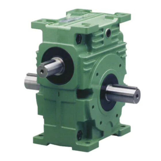
TSUBAKI Worm Gear Reducer
EW/EWJ/EWM/EWJM series
SW/SWJ/SWM/SWJM series
Thank you for purchasing the EW/EWJ/EWM/EWJM or SW/SWJ/SWM/SWJM series worm gear
reducer.
To ensure full use of the features of this product, be sure to carefully read this instruction manual
and refer to it for installation and inspection. This product should be handled by trained individuals.
For special specifications, refer to this instruction manual and the external drawings (specification
and delivery drawings). Contact your distributor or Tsubakimoto Chain Co. if you have any
questions regarding this instruction manual.
Provide the instruction manual at a location that is accessible to the operator.
Keep the instruction manual in a safe place for easy reference before using the product.
Instruction Manual
TSUBAKIMOTO CHAIN CO.
1
EW00E.00TS-4
Printed May 10, 2021
Advertisement
Table of Contents

Subscribe to Our Youtube Channel
Related Manuals for Tsubaki EW Series


Summary of Contents for Tsubaki EW Series
- Page 1 EW00E.00TS-4 Printed May 10, 2021 TSUBAKI Worm Gear Reducer EW/EWJ/EWM/EWJM series SW/SWJ/SWM/SWJM series Instruction Manual Thank you for purchasing the EW/EWJ/EWM/EWJM or SW/SWJ/SWM/SWJM series worm gear reducer. To ensure full use of the features of this product, be sure to carefully read this instruction manual and refer to it for installation and inspection.
-
Page 2: Table Of Contents
Contents Safety Precautions ··························································································· 3 1.After Purchase ······························································································ 5 1-1.Checking the contents ············································································· 5 1-2.Information to provide when contacting customer service ······························· 5 1-3.Model number designation ······································································· 5 2.Transport ····································································································· 11 3.Installation ···································································································· 11 3-1.Solid output shaft type ············································································· 11 3-2.Hollow output shaft type ···········································································... -
Page 3: Safety Precautions
Safety Precautions For the safe use of this product, be sure to follow all items listed below. The reducer should be handled by trained individuals. Be sure to carefully read and familiarize yourself with the contents of the instruction manual before using the product. Provide the instruction manual at a location that is accessible to the operator during actual operation. -
Page 4: Transport
Caution (General) Do not use with specifications other than on the reducer nameplate and the manufacturing specifications. Injury or equipment damage can occur. Do not insert fingers or objects into the openings on the reducer. Electric shock, injury, fire, and equipment damage can occur. Do not use a damaged reducer. - Page 5 [ 1 ] After Purchase 1-1. Checking the contents Check the following items upon receipt of your reducer. Contact your distributor or Tsubakimoto Chain Co. if any defects are found. Caution Check the contents for all ordered parts. Installing an incorrect product can result in injury or equipment damage. Open the packaging right side up.
- Page 6 1-3-1. Model numbers for the EW/EWJ/EWM/EWJM and SW/SWJ/SWM/SWJM series Single Reduction Gear Reducers Series Size Mounting Position Reduction Ratio Shaft Arrangement Motor Capacity Motor Specifications Without motor EWJM With motor SWJMR EWMR SWMR Series Series Mounting Position Reduction Ratio Shaft Arrangement Motor Capacity Motor Specifications EWJ(R)
- Page 7 Double Reduction Gear Reducers Series Size Mounting Position Reduction Ratio Shaft Arrangement Motor Capacity Motor Specifications Without motor 1200 R-LF EWJM With motor EWMR R-LUD SWMR L-RF Series Mounting Position Reduction Ratio Shaft Arrangement Motor Capacity Motor Specifications EWJ50/63 100:1/100 See page 9 0.1 to 0.4kW (3-phase)
- Page 8 *E type applies to the EWJ series. Note 1) E type applies to the EWJ series, and the hollow output shaft type (-H) applies to the EW series. Note 2) If the reducer has a double output shaft, the keyway may not be in the same phase. Contact us if the phases must be matched.
- Page 9 Note 1) Double reduction ratio models EWJ50 and EWJ63 come with the T type shaft arrangement instead of the B type. (Example: EWJ50T100L-R) Note 2) Hollow output shaft type (-H) applies to the EW series. Note 3) If the reducer has a double output shaft, the keyway may not be in the same phase. Contact us if the phases must be matched.
- Page 10 ⑤ EWJM/EWM series Double reduction type (Arrows in figures indicate direction of rotation.) Note 1) Double reduction ratio models EWJ50 and EWJ63 come with the T type shaft arrangement instead of the B type. (Example: EWJM50T100L-R020S) Note 2) Hollow output shaft type (-H) applies to the EWM series. Note 3) If the reducer has a double output shaft, the keyway may not be in the same phase.
-
Page 11: Installation
[ 2 ] Transport Warning Never stand underneath the product while it is being lifted for transport. Falls can result in personal injury. Caution (Transport) Be careful when transporting so as not to drop or overturn the product. Be sure to use lifting hardware when available. Avoid lifting the entire machine by the lifting hardware after installing the machine. - Page 12 Single reduction type: 1/10 to 1/60 Double reduction type: 1/100 to 1/3600 T/B type V type B type V type Input Input Input Input shaft shaft shaft shaft B-L (R) T-(L) R R-LU (D) L-RU (D) R-L (R) L-(L) R LU (D) RU (D) (E-L (R))
- Page 14 3-2. Hollow output shaft type There are three ways to prevent the reducer from rotating: torque arm mount, flange mount, and foot mount (EW-H only). (1) Before inserting the driven shaft into the hollow output shaft, make sure the outside of the driven shaft and the inside of the hollow shaft are free of scratches and dust.
- Page 15 2. Removal procedures Lift the reducer using the lifting bolt. Loosen the end plate bolt which fixes (axial direction) the reducer to the driven shaft. Remove any attachments on the tip of the torque arm, which stops the shaft from rotating, so that it moves freely. Remove the hollow output shaft from the driven shaft while preventing from applying excessive force between it and the housing.
-
Page 16: 4-2. Connection
3-2-3. Installation/removal of foot mounting (EW-H hollow output shaft) Make sure the driven machine and reducer are aligned properly by referring to these installation procedures: Section 3-1-1. Foot mount; Section 3-1-2. Flange mount; Section 3-2-1. Installation/removal of torque arm. Improper alignment can cause unexpected loads which may lead to breakage of the shaft/bearing. - Page 17 In case of the reducer and motor being connected by Jaw-Flex coupling (Applies to motor handling symbol “Y” for models EWJM42, EWJM50 to 70 double reduction type, SWJM35 to 70.) • The coupling hub on the reducer side is set (key and set screw) when shipped. Make sure it has not loosened during transport. •...
-
Page 18: Lubrication
[ 5 ] Lubrication Worm gear reducers are filled with lubrication oil and sealed before shipment. They can be used as is without having to add oil. 5-1.Recommended lubrication oil Daphne Alpha Oil TE260 (IDEMITSU) • Lubrication oil is vital to reducer capacity, life, and efficiency. Use only lubrication oil recommended by Tsubakimoto Chain Co. .Do not mix the oil with other brands. -
Page 19: 5-4.Supplying Grease (Semi-Standard Package)
5-4-2. Approximate greasing volume (*Grease the top of the input shaft.): Input installed on top: (Same as when equipped with motor.) Grease nipple (opposite side) Reduction ratio: 1/10 to 1/60 Unit: g EW Series SW Series Size Size Double reduction ratio: 1/100 to 1/3600... -
Page 20: Operation
[ 6 ] Operation Warning (Operation) Never approach or touch the shaft or other rotating parts during operation. Catching and injury can occur. Caution (Operation) For a specification with a fan cover, do not insert your hand in the fan cover. Otherwise, there is a risk of being caught in those parts resulting in injury. -
Page 21: Maintenance
[ 7 ] Maintenance Warning Never touch the shaft or other rotating parts when maintaining or inspecting the reducer during operation. Catching and personal injury can occur. When performing inspection inside the product while stopped, be sure to stop rotation of the drive and driven equipment and allow the inside to sufficiently cool before inspecting while continually ventilating the inside. -
Page 22: Handling The Standard Motor And Brake Specifications
・ Procedures for replacing oil seals and filters Use the following procedures to replace oil seals and filters installed in the lids, such as the housing, input seal support, output seal support, output bearing support, and motor flange. Check the model number and dimensions in the catalogs or instruction manual to verify that the oil seal or filter for replacement is correct. - Page 23 ● Recommended tolerance for driven shaft diameter: h6 1) Make sure there are no scratches or dust on the periphery of the driven shaft (recommended tolerance: h6), and the inside of the hollow output shaft of the reducer. Using the lifting bolt on the top surface of the reducer, suspend the reducer and insert it into the driven shaft.
-
Page 24: 9-2.Handling The Taper Bush Specifications
1) Loosen the POWER-LOCK tightening bolts in sequence. As mentioned in the notes, do not completely remove the bolts at once. Loosen each tightening bolt head by about 30°. 2) After confirming that the POWER-LOCK has fully released, suspend the reducer by its lifting bolt and remove it from the driven shaft. - Page 25 5) After tightening the bolts, verify that the end face of the hollow output shaft is not interfering with the taper bush. Note) If the end face of the hollow output shaft is interfering, either the shaft diameter of the driven shaft is too small, or the tightening bolts are not tightened evenly.
-
Page 26: Disassembly And Assembly
2) Do not use any bolts other than those supplied with this product. In case of damage or loss, contact your Tsubakimoto Chain Co. dealer for replacement or new bolts. 3) The taper bush tightening bolts are also used as draw bolts during removal. Provide enough room to remove the bolts by referring to the detailed dimensions (bolt lengths and PCD) in the catalog. - Page 27 [ 12 ] Internal Construction and Parts List 12-1. Internal construction The following are typical examples. Use these for reference. [EWJ25 to 42, SWJ25 to 42] EWJ/SWJ input shaft construction EWJ output shaft construction SWJ output shaft construction Thru-hole for M8 bolts (4) [Part Name] For wear parts (bearings, oil seals), refer to the parts list in section 12-2.
- Page 28 [EWJ50 to 70] [EW80 to 200] Part Name] For wear parts (bearings, oil seals), refer to the parts list in section 12-2. Part name Part name Part name Part name Part name Housing Output shaft bearing Plug with hole Hex nut Pressure vent Worm Input shaft oil seal...
- Page 29 [EWJM50 to 70] [EWM80 to 150] [Part Name] For wear parts (bearings, oil seals), refer to the parts list in section 12-2. Part name Part name Part name Part name Part name Part name Housing 7 Output shaft bearing 13 Plug with hole 19 Hex cap bolt 25 Hex nut...
- Page 30 [SWJ50 to 70] [SW80 to 200] [Part Name] For wear parts (bearings, oil seals), refer to the parts list in section 12-2. Part name Part name Part name Part name Part name Input bearing Housing Shim II-B Input oil seal Oil gauge support II Worm...
- Page 31 [SWJ50 to 70] [SW80 to 200] [Part Name] For wear parts (bearings, oil seals), refer to the parts list in section 12-2. Part name Part name Part name Part name Part name Part name Housing Input shaft oil seal Spring washer Hex set screw Hex cap bolt Oil gauge...
- Page 32 3) The filter must also be replaced when replacing oil seals. Contact us for details. 4) Input shaft oil seals are different for double input shaft models. Contact us for details. Made to order, and not available in general market. Contact Tsubaki representative for more information. Double reduction ratio: 1/100 to 1/3600...
- Page 33 Made to order, and not available in general market. Contact Tsubaki representative for more information. EW/EWM hollow output shaft type (EW-H) Reduction ratio: 1/10 to 1/60 Part name Quantity Input shaft bearing A 32009 32011 32211 30311 30312 30314 Input shaft bearing B...
-
Page 34: Storage
Refer to the Input shaft oil seal (M) above. Other sizes are common. 3) The filter must also be replaced when replacing oil seals. Contact us for details. Made to order, and not available in general market. Contact Tsubaki representative for more information. SW/SWM solid output shaft type... -
Page 35: Others
15-2. Warranty coverage During the limited warranty period, a failure in a Tsubaki product installed, used, and maintained according to the catalog, instruction manual, or other appropriate documents can be returned to Tsubaki for replacement or repair free of charge. - Page 36 [MENO]...
- Page 37 1-1, Kohtari-Kuresumi, Nagaokakyo TSUBAKIMOTO CHAIN CO. Kyoto 617- 0833 Japan Website: https://tsubakimoto.com/ Global Associated Partners: U.S. Tsubaki Power Transmission, LLC Tsubakimoto Singapore Pte. Ltd. Tsubakimoto Europe B.V. https://www.ustsubaki.com/ https://tsubaki.sg/ https://tsubaki.eu/ Tsubaki of Canada Limited Taiwan Tsubakimoto Co. Tsubakimoto U.K. Ltd.
Need help?
Do you have a question about the EW Series and is the answer not in the manual?
Questions and answers