Tektronix P6248 Service Manual
1.7 ghz typical differential probe
Hide thumbs
Also See for P6248:
- Instructions manual (40 pages) ,
- Service manual (55 pages) ,
- Instructions manual (188 pages)
Table of Contents
Advertisement
Quick Links
Service Manual
P6248
1.7 GHz (Typical)
Differential Probe
071-0573-03
Warning
The servicing instructions are for use by qualified
personnel only. To avoid personal injury, do not
perform any servicing unless you are qualified to
do so. Refer to all safety summaries prior to
performing service.
*P071057303*
071057303
Advertisement
Table of Contents

Subscribe to Our Youtube Channel
Related Manuals for Tektronix P6248


Summary of Contents for Tektronix P6248
- Page 1 Service Manual P6248 1.7 GHz (Typical) Differential Probe 071-0573-03 Warning The servicing instructions are for use by qualified personnel only. To avoid personal injury, do not perform any servicing unless you are qualified to do so. Refer to all safety summaries prior to performing service.
- Page 2 Copyright © Tektronix, Inc. All rights reserved. Tektronix products are covered by U.S. and foreign patents, issued and pending. Information in this publication supercedes that in all previously published material. Specifications and price change privileges reserved. Tektronix, Inc., P.O. Box 500, Beaverton, OR 97077 TEKTRONIX, TEK, and TEKPROBE are registered trademarks of Tektronix, Inc.
- Page 3 Tektronix, with shipping charges prepaid. Tektronix shall pay for the return of the product to Customer if the shipment is to a location within the country in which the Tektronix service center is located.
-
Page 5: Table Of Contents
CMRR (Common-Mode Rejection Ratio) ......P6248 1.7 GHz Differential Probe Service Manual... - Page 6 Figure 19: Setup for the CMRR tests ......P6248 1.7 GHz Differential Probe Service Manual...
-
Page 7: General Safety Summary
Provide Proper Ventilation. Refer to the manual’s installation instructions for details on installing the product so it has proper ventilation. Symbols and Terms Terms in this Manual. These terms may appear in this manual: P6248 1.7 GHz Differential Probe Service Manual... - Page 8 CAUTION indicates a hazard to property including the product. Symbols on the Product. The following symbols may appear on the product: Double CAUTION WARNING Protective Ground Insulated Refer to Manual High Voltage (Earth) Terminal P6248 1.7 GHz Differential Probe Service Manual...
-
Page 9: Service Safety Summary
Do Not Service Alone. Do not perform internal service or adjustments of this product unless another person capable of rendering first aid and resuscitation is present. Use Care When Servicing With Power On. To avoid electric shock, do not touch exposed connections. P6248 1.7 GHz Differential Probe Service Manual... - Page 10 Service Safety Summary P6248 1.7 GHz Differential Probe Service Manual...
-
Page 11: Preface
This phone number is toll free in North America. After office hours, please leave a voice mail message. Outside North America, contact a Tektronix sales office or distributor; see the Tektronix web site for a list of offices. P6248 1.7 GHz Differential Probe Service Manual... - Page 12 Preface viii P6248 1.7 GHz Differential Probe Service Manual...
-
Page 13: Specifications
Specifications The specifications in Tables 1 through 4 apply to a P6248 differential probe installed on a Tektronix TDS 694C oscilloscope. When the probe is used with another oscilloscope, the oscilloscope must have an input impedance of 50 Ω. The probe must have a warm-up period of at least 20 minutes and be in an environment that does not exceed the limits described in Table 1. -
Page 14: Typical Characteristics
DC to ≥1.7 GHz (- - 3dB) @ ≤27_ C (÷1 range) Bandwidth (probe only) DC to ≥1.85 GHz (- - 3dB) @ ≤27_ C (÷10 range) Rise time (probe and oscilloscope) <265 ps P6248 1.7 GHz Differential Probe Service Manual... -
Page 15: Figure 1: Typical Common-Mode Rejection Ratio
Figure 1: Typical Common-Mode Rejection Ratio (÷1 and ÷10 attenuation) 100 k 10 k Impedance (Ω) 250 M 500 M 750 M 1 .25 G 1 .50 G 1 .75 G Frequency (Hz) Figure 2: Typical differential input impedance versus frequency P6248 1.7 GHz Differential Probe Service Manual... -
Page 16: Nominal Characteristics
Table 4: Nominal electrical characteristics Characteristic Description Input configuration Differential (two inputs, + and - - ), with case ground Output coupling ÷1 and ÷10 Attenuation settings Terminate output into 50 Ω Termination P6248 1.7 GHz Differential Probe Service Manual... -
Page 17: Performance Verification
Performance Verification Use the following procedures to verify the warranted specifications of the P6248 Differential Probe. Before beginning these procedures, refer to page 18 and photocopy the test record and use it to record the performance test results. The recommended calibration interval is one year. -
Page 18: Preparation
6. Allow the probe and test equipment to warm up for 20 minutes at an ambient temperature of 20_ C to 30_ C (68_ F to 86_ F). Perform the verification procedures in order. P6248 1.7 GHz Differential Probe Service Manual... -
Page 19: Output Offset Voltage
3. Verify that the output voltage is 10 mV. ÷ 4. Change the probe attenuation to ≤ ± 5. Verify that the output voltage is 10 mV. 6. Keep the output connections for the next procedure (DC attenuation accuracy). P6248 1.7 GHz Differential Probe Service Manual... -
Page 20: Dc Attenuation Accuracy
14. Calculate the attenuation as follows: (V 1 - - V 1 - - V 15. Verify that the attenuation is in the range of 0.98 to 1.02. 16. Keep the output connections for the next procedure. P6248 1.7 GHz Differential Probe Service Manual... -
Page 21: Differential Signal Range
± 4. Set the differential mode source to 8.5 V 100 mV. Record the actual voltage as V 5. Measure and record the output voltage as V ÷ 6. Calculate attenuation as V P6248 1.7 GHz Differential Probe Service Manual... - Page 22 19. Measure and record the output voltage as V ÷ 20. Calculate the attenuation as V 21. Verify that the attenuation is in the range of 0.95 to 1.05. 22. Remove all connections. P6248 1.7 GHz Differential Probe Service Manual...
-
Page 23: Rise Time
Figure 7. The system and probe rise time (t ) that you measure in steps 20 and 28 is used to calculate the probe rise time (t ) in steps 21 and 29. P6248 1.7 GHz Differential Probe Service Manual... -
Page 24: Figure 7: Rise Time Setup For Test System With Probe
15. Set the probe attenuation to 16. Adjust the oscilloscope vertical sensitivity to 50 mV/div. 17. Adjust the oscilloscope vertical positioning to center the signal on screen. 18. Adjust the oscilloscope horizontal sensitivity to 500 ps/div. P6248 1.7 GHz Differential Probe Service Manual... - Page 25 Record the rise time for s+p. 29. Calculate the probe rise time using the following formula: − t (s+p) ÷ 30. Record the calculated probe rise time for 10 on the test record. P6248 1.7 GHz Differential Probe Service Manual...
-
Page 26: Common-Mode Rejection Ratio
NOTE. Do not remove the end connected to the network analyzer. Connect the cable to the BNC-to-Probe Tip adapter. 2. Move the probe from the 1103 channel 2 to channel 1 input connector. 3. The setup should now appear as shown in Figure 8. P6248 1.7 GHz Differential Probe Service Manual... -
Page 27: Figure 8: Setup For Cmrr Test
1 GHz. Analyzers with marker capability can do this directly by setting the marker intercepts at 1, 100, 500, and 1 GHz. If necessary, turn on the network analyzer Average mode with 16 averages to stabilize the reading. P6248 1.7 GHz Differential Probe Service Manual... -
Page 28: Tekprobe Communication (Operational Check)
4. Press the CH 1 button. 5. Use the Vertical Scale knob to set the vertical scale factor to 100 mV/div. 6. Press the Vertical Menu button. 7. Select the Coupling menu (left button along lower bezel). P6248 1.7 GHz Differential Probe Service Manual... - Page 29 12. Verify that the channel 1 scale factor is 1 V/div. ÷ 13. Set the probe attenuation to 14. Verify that the channel 1 scale factor is 100 mV/div. This completes the functional check and the performance verification. P6248 1.7 GHz Differential Probe Service Manual...
- Page 30 ÷10 setting 1 MHz - - 65 dB _____________ _____________ 100 MHz - - 45 dB _____________ _____________ 500 MHz - - 40 dB _____________ _____________ 1 GHz - - 38 dB _____________ _____________ P6248 1.7 GHz Differential Probe Service Manual...
-
Page 31: Adjustment Procedures
10 V , Separate Trigger or Sync pk-pk (Square and sine wave output output) 50 Ω terminator 50 Ω ± 1 Ω 011-0049-01 (needed only if oscilloscope does not support 50 Ω termination) P6248 1.7 GHz Differential Probe Service Manual... -
Page 32: Figure 9: Adjustment Locations
Figure 9 shows the location of the adjustments inside the control box. ÷ 1 Offset ÷ 10 Gain ÷ 1 Gain ÷ 10 Offset ÷ 10 DC CMRR ÷ 1 DC CMRR ÷ 10 AC CMRR ÷ 1 AC CMRR Figure 9: Adjustment locations P6248 1.7 GHz Differential Probe Service Manual... -
Page 33: Offset (Preliminary)
1 mV. ÷ 5. Change the probe attenuation to ÷ ± 6. Adjust the 10 offset adjustment for 0 mV 1 mV. 7. Keep the output cable set up for the next step. P6248 1.7 GHz Differential Probe Service Manual... -
Page 34: Gain
2. Set the DMM monitoring the output to DC Volts, 2 or 3 volt range. 3. Set the DMM monitoring the input to the 2 or 3 volt range. Keep averaging turned on. ÷ 4. Set the probe to 1 attenuation. P6248 1.7 GHz Differential Probe Service Manual... -
Page 35: Offset (Final)
NOTE. Do not use the BNC to probe tip adapter for this connection. The power level of the generator will exceed the terminator rating. P6248 1.7 GHz Differential Probe Service Manual... -
Page 36: Figure 12: Setup For Dc Cmrr And Ac Cmrr Adjustments
7. Adjust the 1 DC CMRR for minimum amplitude in the flat portions of the displayed waveform. This adjustment does not affect the leading edge transitions. Increase the vertical sensitivity as the amplitude decreases. P6248 1.7 GHz Differential Probe Service Manual... -
Page 37: Ac Cmrr
Repeat the DC CMRR adjustment steps 5 through 12. 10. Remove all connections from the probe. Carefully replace the top cover of the control box and the four retaining screws. This completes the adjustment procedures. P6248 1.7 GHz Differential Probe Service Manual... - Page 38 Adjustment Procedures P6248 1.7 GHz Differential Probe Service Manual...
-
Page 39: Maintenance
Maintenance The procedures in this section describe how to maintain and repair the P6248 differential probe. Cleaning Remove dirt with a soft cloth dampened in a mild detergent and water solution or isopropyl alcohol. CAUTION. To avoid damaging the probe, use only a mild detergent and water solution or isopropyl alcohol;... -
Page 40: Removing And Replacing The Tekprobe Interface Collar
2. To replace the collar, align the smaller group of pins with the smaller of the two holes in the interface collar and align the tabs with the slots. Gently press the two pieces together. See Figure 14. Slot Figure 14: Replacing the TEKPROBE collar P6248 1.7 GHz Differential Probe Service Manual... -
Page 41: Options
Options Option 95 is a report of the calibration data. This option must be ordered at the time of purchase. P6248 1.7 GHz Differential Probe Service Manual... - Page 42 Options P6248 1.7 GHz Differential Probe Service Manual...
-
Page 43: Replaceable Parts
Replaceable Parts Figure 15: P6248 replaceable parts P6248 1.7 GHz Differential Probe Service Manual... - Page 44 CALIBRATION STANDARD,P6248 - - 2 211-0001-00 SCREW,MACHINE:2-56 X 0.25,PNH,STL CD PL,POZ 80009 ORDER BY DESCRIPTION - - 3 131-3627-02 CONTACT,ELEC:GOLD PLATED TIP 80009 131-3627-02 - - 4 205-0191-01 SHELL,ELEC CONN:BNC,ABS,DOVE GRAY 80009 205-0191-01 P6248 1.7 GHz Differential Probe Service Manual...
-
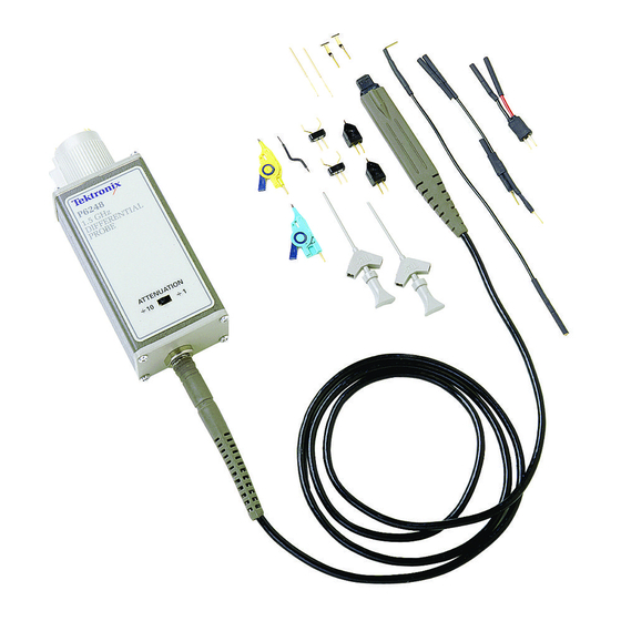
Page 45: Figure 16: P6248 Standard Accessories
Replaceable Parts Figure 16: P6248 standard accessories P6248 1.7 GHz Differential Probe Service Manual... - Page 46 80009 016-1315-00 VARIOUS COLORS - - 14 006-7164-00 BOX,PLASTIC:4.625 X 2.875 X 1.0 80009 006-7164-00 - - 15 016-1879-00 CASE,CARRYING:PROBE CARRYING CASE,P6248 80009 016-1879-00 071-0566-XX MANUAL,TECH:INSTRUCTION,P6248 80009 071-0566-XX 071-0573-XX MANUAL, TECH:SERVICE,P6248 80009 071-0573-XX P6248 1.7 GHz Differential Probe Service Manual...
-
Page 47: Figure 17: P6248 Optional Accessories
Replaceable Parts Figure 17: P6248 optional accessories P6248 1.7 GHz Differential Probe Service Manual... - Page 48 CA ASSY,RF:COAXIAL,RFD,50 OHM,20 L,BNC, 80009 012-0076-00 MALE,STR,BOTH ENDS,W/STRAIN RELIEF BOOT BOTH ENDS - - 5 1103 TEKTRONIX 1103 TEKPROBE POWER SUPPLY 80009 ORDER BY DESCRIPTION - - 6 679-5027-00 CKT BD SUBASSY:1394 ADAPTER 80009 679-5027-00 P6248 1.7 GHz Differential Probe Service Manual...
- Page 49 SUITE 120 24931 BERG ELECTRONICS INC BERG ELECTRONICS RF/COAXIAL DIV FRANKLIN, IN 46131 2100 EARLYWOOD DR PO BOX 547 80009 TEKTRONIX INC 14150 SW KARL BRAUN DR BEAVERTON, OR 97077-0001 PO BOX 500 P6248 1.7 GHz Differential Probe Service Manual...
- Page 50 Replaceable Parts P6248 1.7 GHz Differential Probe Service Manual...
-
Page 51: Appendix A: Alternate Verification Procedures
Tektronix Type 1103 BNC-to-Type-N coax adapt- Type N-male-to-BNC female 103-0045-00 ers (2) 50 Ω, 18 inch BNC cables (2) 012-0076-00 Probe tip adapters (included in the standard probe tip 020-2203-00 BNC-to-probe tip accessory kit) P6248 1.7 GHz Differential Probe Service Manual... -
Page 52: Preparation
4. Turn on the 1103 power supply. 5. Set the 1103 offset to off (button not illuminated). 6. Allow at least 20 minutes for the probe and equipment to warm up. Perform the verification procedures in order. P6248 1.7 GHz Differential Probe Service Manual... -
Page 53: Cmrr (Common-Mode Rejection Ratio)
Do not allow kinks, loops or other deformities in the probe cable, and maintain a maximum distance between the probe head and the probe control box. P6248 1.7 GHz Differential Probe Service Manual... -
Page 54: Figure 19: Setup For The Cmrr Tests
10 measured feed through column of Table 9 on page 43. ÷ (These values are 20 dB lower than the specification to account for the attenuation. ) 8. Set the synthesizer to 100 MHz and 0 dBm. P6248 1.7 GHz Differential Probe Service Manual... - Page 55 ≥ 20 dB ≤ - - 35 dBm ≤ - - 40 dBm 500 MHz ≥ 30 dB ≥ 18 dB ≤ - - 30 dBm ≤ - - 38 dBm 1 GHz P6248 1.7 GHz Differential Probe Service Manual...
- Page 56 Appendix A: Alternate Verification Procedures P6248 1.7 GHz Differential Probe Service Manual...
Need help?
Do you have a question about the P6248 and is the answer not in the manual?
Questions and answers