Table of Contents
Advertisement
Advertisement
Table of Contents

Related Manuals for Motorola MD1600


Summary of Contents for Motorola MD1600
- Page 1 MD1600 User Manual VER: 1.0...
-
Page 2: Table Of Contents
User Manual Contents Contents ........................i 1 Safety Precautions ....................1 Default Safety Language in manual ..............2 2 Overview......................3 2.1 Application ....................3 2.2 Features ...................... 4 2.3 Standards Compatibility and Compliance ............. 5 3 Hardware Description and Installation ..............6 3.1 Hardware Description .................. - Page 3 User Manual 5.2.3 LAN Configuration ..............51 5.2.4 NAT 57 5.2.5 Security ..................61 5.2.6 Parental Control ................ 64 5.2.7 Quality of Service ..............66 5.2.8 Routing ..................70 5.2.9 DNS ..................74 5.2.10 DSL ..................75 5.2.11 UPnP ..................76 5.2.12 DNS Proxy ................
- Page 4 User Manual 5.5.7 Update Software ..............114 5.5.8 Reboot ..................115 6 Q&A ......................... 116 ..........................116 7 Technical Support .................... 117 We like to help..................... 117...
-
Page 5: Safety Precautions
All guidelines of this and of the computer manufacture must therefore be allowed at all times to ensure the safe use of the equipment. MOTOROLA and MTRLC assume no liability for damage caused by any improper use of the DSL router. - Page 6 User Manual Do not put this device close to a place where a heat source exits or high temperature occurs. Avoid placing the device in direct sunlight. Do not put this device close to a place where it is high moisture or wet. Do ...
- Page 7 If your home has specially wired alarm equipment connected to the telephone line, ensure the installation of this MD1600 does not disable your alarm equipment. If you have questions about what will disable alarm equipment, consult your telephone company or a qualified installer.
-
Page 8: Overview
Overview The xDSL Router integrates wireless LAN, and USB storage into one unit. It is designed to provide a simple and cost-effective xDSL Internet connection for a private Ethernet and 802.11g/802.11b/802.11n wireless network. The Router combines high-speed xDSL Internet connection, IP routing for the LAN and wireless connectivity in one package. -
Page 9: Standards Compatibility And Compliance
User-friendly GUI for web configuration Several pre-configured popular games. Just enable the game and the port settings are automatically configured. Compatible with all standard Internet applications Industry standard and interoperable xDSL interface Simple web-based status page displays a snapshot of system configuration, and links to the configuration pages ... - Page 10 ITU G.992.3 (ADSL2) ITU G.992.5 (ADSL2+) ANSI T1.413 Issue 2 IEEE 802.3 IEEE 802.3u IEEE 802.11b IEEE 802.11g IEEE 802.11n...
-
Page 11: Hardware Description And Installation
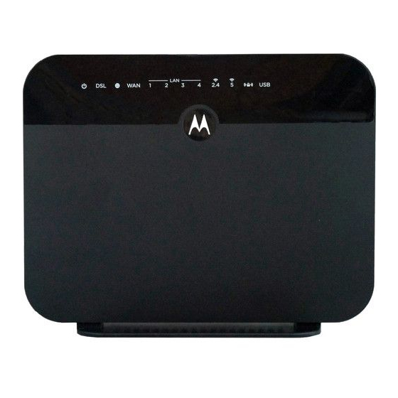
User Manual Hardware Description and Installation Note: The figures in this document are for reference only. Hardware Description Front Panel 2.1.1 Figure 1 Front panel The following table describes the indicators on the front panel. Indicator Color Status Description The device is powered on and the device operates normally. -
Page 12: Rear Panel And Side Panel
User Manual Indicator Color Status Description The Ethernet interface is disconnected. The connection of USB flash disk has established. Green Blink Data is being transmitted. No signal is detected. WLAN is enabled. Data is being transmitted through the wireless WLAN Green Blink interface. -
Page 13: Hardware Installation
User Manual The following table describes the interfaces or the buttons. Interface Description RJ-11 port: Connect the router to DSL connector or splitter through telephone cable. RJ-45 port, for connecting the router to a PC or another network LAN 4~1 device. -
Page 14: Connecting The Device
User Manual walls, ceilings, or other objects that the wireless signals must pass through limit signal range. Typical ranges vary depending on types of materials and background RF noise in your home or business. Connecting the Device 2.2.2 Connect the DSL port of the router and the Modem port of the splitter Step 1 with a telephone cable;... -
Page 15: Pc Network Configuration And Login
User Manual PC Network Configuration and Login PC Network Configuration Each network interface on the PC should either be configured with a statically defined IP address and DNS address, or be instructed to automatically obtain an IP address using the network DHCP server. DSL router provides a DHCP server on its LAN and it is recommended to configure your LAN to automatically obtain its IP address and DNS server IP address. - Page 16 User Manual Figure 5 IP and DNS configuration TCP/IP configuration steps for Windows XP are as follows: Choose Start > Control Panel > Network Connections. Right-click the Ethernet connection icon and choose Properties. On the General tab, select the Internet Protocol (TCP/IP) component and click Properties.
-
Page 17: Logging In To The Dsl Router
User Manual Select the Obtain DNS server address automatically radio button. Click OK to save the settings. Logging In to the DSL Router To log in to the DSL router, do as follows: Open a Web browser on your computer. Enter http://192.168.1.1 (the default IP address of the DSL router) in the address bar. -
Page 18: Web-Based Management
User Manual After logging in to the DSL router as a super user, you can query, configure, and modify all the settings, and diagnose the system. Web-Based Management This chapter describes how to use Web-based management of the DSL router, which allows you to configure and control all of DSL router features and system parameters in a user-friendly GUI. -
Page 19: Wan
User Manual This page displays the device information such as the board ID, software version, and the information of your WAN connection such as the upstream rate and the LAN address. 4.1.2 Choose Device Info > WAN and the following page appears. -
Page 20: Statistics
User Manual This page displays the information of the WAN interface, such as the connection status, and the IP address. Statistics 4.1.3 4.1.4 Choose Device Info > Statistics > LAN and the following page appears. In this page, you can view the statistical information about the recevied and transmitted data packets of the Ethernet and wireless interfaces. -
Page 21: Xtm
User Manual In this page, you can view the statistical information about the recevied and transmitted data packets of the WAN interface. Click Reset Statistics to restore the values to zero and recount them. 4.1.6 Choose Device Info > Statistics > xTM and the following page appears. In this page, you can view the statistical information about the recevied and transmitted data packets at the xTM interfaces. - Page 22 User Manual...
- Page 23 User Manual In this page, you can view the statistical information about the recevied and transmitted data packets of the xDSL interfaces. Click xDSL BER Test to test the xDSL Bit Error Rate. Click Reset Statistics to restore the values to zero and recount them. xDSL BER Test Click xDSL BER Test to perform a bit error rate (BER) test on the DSL line.
-
Page 24: Route
User Manual When the ADSL BER test completes, the following page appears. Note: If the BER reaches e-5, you cannot access the Internet. Route 4.1.8 Choose Device Info > Route and the following page appears. In this page, you can view the route table information. -
Page 25: Arp
User Manual 4.1.9 Choose Device Info > ARP and the following page appears. In this page, you can view the MAC address and IP address information of the device connected to the router. DHCP 4.1.10 Choose Device Info > DHCP and the following page appears. In this page, you can view the host name, the IP address assigned by the DHCP server, the MAC address this is corresponding to the IP address, and the DHCP lease time. - Page 26 User Manual...
-
Page 27: Layer2 Interface
User Manual Layer2 Interface 4.2.1 4.2.1.1 ATM Interface Choose Advanced Setup > Layer2 Interface > ATM Interface . In this page, you can add or remove to configure DSL ATM Interfaces. Click Add to add ATM Interface and the following page appears. - Page 28 User Manual In this page, you can enter this PVC (VPI and VCI) value, and select DSL link type (EoA is for PPPoE, IPoE, and Bridge.), encapsulation mode, service category. VPI (Virtual Path Identifier): The virtual path between two points in an ATM network, and its valid value is from 0 to 255.
- Page 29 User Manual DSL Link Type: EoA (it is for PPPoE, IPoE, and Bridge), PPPoA, or IPoA Encapsulation Mode: LLC/SNAP-BRIDGING, or VC/MUX Service Category: UBR Without PCR, UBR With PCR, CBR, Non Realtime VBR, Realtime VBR. Select Scheduler for Queues of Equal Precedence as the Default Queue: Weighted Round Robin or Weighted Fair Queuing.
- Page 30 User Manual In this page, you can configuration the PTM interface Click Apply/Save. Click Apply/Save to save the configuration, and return the following page: If you want to remove this Interface, please select the Remove check box and click Remove.
-
Page 31: Wan Service
User Manual 4.2.1.3 ETH Interface Choose Advanced Setup > Layer2 Interface > ETH Interface, and the following page appears. In this page, you can add or remove to configure ETH WAN Interfaces. Click Add and the following page appears. In this page, you can select a ETH port. Click Apply/Save to save configuration. Note: If ETH Interface is selected, there are two WAN service types (PPPoE and IPoE). - Page 32 User Manual 4.2.2.1 Adding a PPPoE WAN Service This section describes the steps for adding the PPPoE WAN service. In the Wide Area Network (WAN) Service Setup page, click the Add Step1 button to display the following page. (At first, you must add a proper ATM interface for this WAN service.) In this page, you can select a ATM Interface for the WAN service.
- Page 33 User Manual In this page, select the WAN service type to be PPP over Ethernet Step3 (PPPoE). Click Next to display the following page.
- Page 34 User Manual In this page, you can modify the PPP username, PPP password, PPPoE Step4 service name and authentication method. PPP Username: The correct user name provided by your ISP. PPP Password: The correct password provided by your ISP. ...
- Page 35 User Manual Dial on demand (with idle timeout timer): If this function is enabled, you need to enter the idle timeout time. Within the preset minutes, if the modem does not detect the flow of the user continuously, the modem automatically stops the PPPoE connection.
- Page 36 User Manual In this page, select a preferred WAN interface as the system default Step6 gateway and then click Next to display the following page. In this page, you can obtain the DNS server addresses from the selected Step7 WAN interface. Click Next, and the following page appears.
- Page 37 User Manual In this page, it displays the information about the PPPoE settngs. Click Step8 Apply/Save to save and apply the settings. 4.2.2.2 Adding a MER (IPoE) WAN service This section describes the steps for adding the MER WAN service. Step1 In the Wide Area Network (WAN) Service Setup page, click the Add button to display the following page.
- Page 38 User Manual Step3 In this page, select the WAN service type to be IP over Ethernet, enter the service description for this service. After finishing setting, click Next to display the following page.
- Page 39 User Manual Step4 In this page, you may modify the WAN IP settings. You may select obtain an IP address automatically or manually enter the IP address provided by your ISP. Click Next and the following page appears. Note: If selecting Obtain an IP address automatically, DHCP will be enabled for PVC in MER mode.
- Page 40 User Manual Step5 In this page, you can set the network address translation settings,for example, enabling NAT, enabling firewall, and enabling IGMP multicast. After finishing setting, click Next and the following page appears. Step6 In this page, select a preferred WAN interface as the system default gateway and then click Next to display the following page.
- Page 41 User Manual Step7 In this page, you can obtain the DNS server addresses from the selected WAN interface. After finishing setting, click Next to display the following page.
- Page 42 User Manual Step8 In this page, it displays the information about the IPoE settngs.Click Apply/Save to save and apply the settings. 4.2.2.3 Adding a PPPoA WAN service This section describes the steps for adding the PPPoA WAN service. Step1 Choose Advanced Setup > Layer2 Interface > ATM Interface to dsipaly the DSL ATM Interface Configuration page.
- Page 43 User Manual Step2 Select the DSL link type to be PPPoA, and select the encapsulation mode to be VC/MUX (according to the uplink equipment). After finishing setting, click the Apply/Save button to apply the setings. Step3 Choose WAN Service and click Add to display the following page.
- Page 44 User Manual Step4 Select the proper interface for the WAN service, and then click Next to display the following page. Step5 In this page, you may modify the service description. Click Next to display the following page.
- Page 45 User Manual PPP Username: The correct user name provided by your ISP. PPP Password: The correct password provided by your ISP. Authentication Method: The value can be AUTO, PAP, CHAP, or MSCHAP. Usually, you can select AUTO. ...
- Page 46 User Manual dial-up. If this function is enabled, the modem uses this IP address as the WAN IP address. Enable PPP Debug Mode:Enable or disable this function. Enable IGMP Multicast Proxy: If you want PPPoE mode to support IPTV, enable it.
- Page 47 User Manual Step8 In this page, you can obtain the DNS server addresses from the selected WAN interface. After finishing setting, click Next to display the following page.
- Page 48 User Manual Step9 In this page, it displays the information about the PPPoA settngs.Click Apply/Save to apply the settings. You can modify the settings by clicking the Back button if necessary. 4.2.2.4 Adding an IPoA WAN service This section describes the steps for adding the IPoA WAN service. Step1 Choose Advanced Setup >...
- Page 49 User Manual Step2 Select the DSL link type to be IPoA, and select the encapsulation mode to be LLC/SNAP-ROUTING (according to the uplink equipment). After finishing setting, click the Apply/Save button to save the settings. Step3 Choose WAN Service and click Add to display the following page.
- Page 50 User Manual Step4 Select the proper interface for the WAN service ,and then click Next to display the following page. Step5 In this page, you may modify the service description. Click Next to display the following page.
- Page 51 User Manual Step6 In this page, enter the WAN IP address, the WAN subnet mask, and primary DNS server provided by your ISP and then click Next to display the following page. In this page, Network Address Translation (NAT) allows you to share one Wide Area Network (WAN) IP address for multiple computers on your Local Area Network (LAN).
- Page 52 User Manual Step7 After finishing setting, click Next to display the following page. Step8 In this page, select a preferred WAN interface as the system default gateway and then click Next to display the following page.
- Page 53 User Manual Step9 In this page, you can obtain the DNS server addresses from the selected WAN interface. After finishing setting, click Next to display the following page. Step10 In this page, it displays the information about the IPoA settngs. Click Apply/Save to save and apply the settings.
- Page 54 User Manual Select the proper ATM Interface and then click Next to display the following page.
- Page 55 User Manual In this page, you can select the WAN service type, and modify the service description for this service. After finishing setting, click Next to display the following page.
-
Page 56: Lan Configuration
User Manual In this page, it displays the information about the bridge settngs. Click Apply/Save to save and apply the settings. You can modify the settings by clicking the Back button if necessary. LAN Configuration 4.2.3 Choose Advanced Setup > LAN, and the following page appears. - Page 57 User Manual In this page, you can configure an IP address for the DSL router, enable IGMP snooping, enable or disable the DHCP server, edit the DHCP option, configure the DHCP advanced setup and set the binding between a MAC address and an IP address.
- Page 58 User Manual Configuring the DHCP Server If you enable the DHCP sever, the clients will automatically acquire the IP address from the DHCP server. If the DHCP server is disabled, you need to manually set the start IP address, end IP address and the lease time for the clients in the LAN. Editing the DHCP Option60 Click the Edit DHCP Option60 button in the Local Area Network (LAN) Setup page to display the DHCP Option60 Setup page.
- Page 59 User Manual DHCP Advanced Setup Click the DHCP Advance Setup button in the Local Area Network (LAN) Setup page to display the following page. In this page, you can enable or disable DHCP for every LAN interface. Configuring the DHCP Static IP Lease List The lease list of static IP address can reserve the static IP addresses for the hosts with the specific MAC addresses.
- Page 60 User Manual In this page, enter the MAC address of the LAN host and the static IP address that is reserved for the host, and then click the Apply/Save button to apply the settings. Configuring the Second IP Address and Subnet Mask for a LAN Interface In the Local Area Network (LAN) Setup page, you are allowed to set the second IP address and the subnet mask for a LAN interface.
- Page 61 User Manual In this page, you can set an IP address for the DSL IPv6 router, enable the DHCPv6 server, enable RADVD and enable the MLD snooping function. Enable DHCPv6 Server: WIDE-DHCPv6 is an open-source implementation of dynamic host configuration protocol for IPv6 (DHCPv6) originally developed by the KAME project.
-
Page 62: Nat
User Manual After finishing setting, click the Save/Apply button to apply the settings. 4.2.4 4.2.4.1 Virtual Servers Firewall can prevent unexpected traffic on the Internet from your host on the LAN. The virtual server can create a channel that can pass through the firewall. In that case, the host on the Internet can communicate with a host on your LAN within certain port range. - Page 63 User Manual Use interface: Select an interface that you want to configure. Select a Service: Select a proper service in the drop-down list. Custom Server: Enter a new service name to establish a user service type. Server IP Address: Assign an IP address to virtual server.
- Page 64 User Manual Internal Port End: When selecting a service, the port number will automatically be displayed. You can modify it if necessary. After finishing setting, click Save/Apply to save and apply the settings. Step 5 4.2.4.2 Port Triggering Some applications need some ports to be opened in the firewall for the remote access.
- Page 65 User Manual Use interface: Select an interface that you want to configure. Select an application: Select a proper application in the drop-down list. Custom application: Manually define an application. Trigger port Start: The start port number that LAN uses to trigger the open port.
-
Page 66: Security
User Manual You can use a single port number, several port numbers separated by commas, port blocks consisting of two port numbers separated by a dash, or any combination of these, for example 80, 90-140, 180. 4.2.4.3 DMZ Host DMZ allows all the ports of a PC on your LAN to be exposed to the Internet. Set the IP address of the PC to be DMZ host, so that the DMZ host will not be blocked by firewall. - Page 67 User Manual Click Modify Firewall or Remove Firewall to modify or remove the firewall. And click Modify Rule or Remove Rule to modify or remove the rule. Click Add Firewall, and the following page appears. name: The name of firewall. ...
- Page 68 User Manual Note: MAC filtering is only effective on ATM PVCs configured in bridge mode. Choose Security > MAC Filtering and the following page appears. In this page, you can add or remove the MAC filtering rule. You may change the MAC filtering policy from FORWARDED to BLOCKED by clicking the Change Policy button.
-
Page 69: Parental Control
User Manual Protocol Type: Select the proper protocol type. Destination MAC Address: Enter the destination MAC address. Source MAC Address: Enter the source MAC address. Frame Direction: The direction of transmission frame. WAN Interface (Configured in bridge mode only): Select the proper WAN interface in the drop-down list. - Page 70 User Manual This page is used to control the time restriction to a special LAN device that connects to the DSL router. In this page, se the user name and configure the time settings. After finishing setting, click the Apply/Save button to save and apply the settings. Url Filter Click Advanced Setup >...
-
Page 71: Quality Of Service
User Manual In this page, enter the URL address and its corresponding port number. For example, enter the URL address http://www.google.com and the port number 80, and then click the Apply/Save button. See the following figure: Quality of Service 4.2.7 Enabling QoS Choose Advance Setup >... - Page 72 User Manual Select Enable QoS to enable QoS and configure the default DSCP mark. In this page, enable the QoS function and select the default DSCP mark. After finishing setting, click Apply/Save to save and apply the settings. Note: If the Enable Qos checkbox is not selected, all QoS will be disabled for all interfaces.
- Page 73 User Manual In this page, you can enable, add or remove a QoS rule. Note: The lower integer value for precedence indicates the higher priority. Click the Add button to display the following page. Name: Enter the name of QoS queue.
- Page 74 User Manual Enable: Enable or disable the QoS queue. Interface: Select the proper interface for the QoS queue. After finishing setting, click Apply/Save to save and apply the settings. QoS Classification Choose Advanced Setup > Quality of Service > Qos Classification and the following page appears.
-
Page 75: Routing
User Manual Routing 4.2.8 Default Gateway Choose Advanced Setup > Routing > Default Gateway, and the following page appears. - Page 76 User Manual In this page, you can modify the default gateway settings. Select a proper WAN interface in the drop-down list of Selected WAN Interface as the system default gateway. After finishing setting, click Apply/Save to save and apply the settings. Static Route Choose Advanced Setup >...
- Page 77 User Manual IP Version: Select the IP version. Destination IP address/prefix length: Enter the destination IP address. Interface: select the proper interface for the rule. Gateway IP Address: The next-hop IP address. Metric: The metric value of routing. After finishing setting, click Apply/Save to save and apply the settings.
- Page 78 User Manual In this page, enter the policy name, source IP and default gateway, and select the physical LAN port and interface. After finishing setting, click Apply/Save to save and apply the settings. Choose Advanced Setup > Routing > RIP and the following page appears. In this page, if you want to configure an individual interface, select the desired RIP version and operation, and then select the Enabled checkbox for the interface.
-
Page 79: Dns
User Manual 4.2.9 DNS Server Choose Advanced Setup > DNS > DNS Server and the following page appears. In this page, you can select a DNS server interface from the available interfaces, manually enter the DNS server addresses, or obtain the DNS address from a WAN interface. -
Page 80: Dsl
User Manual In this page, you are allowed to modify the DDNS settings. Click the Add button to display the following page. D-DNS provider: Select a proper DDNS server in the drop-down list. Hostname: It is the domain name and it can be modified. ... -
Page 81: Upnp
User Manual In this page, you can set the DSL settings. Usually, you do not need to modify the factory default settings. After finishing setting, click Apply/Save to save and apply the settings. UPnP 4.2.11 Choose Advanced Setup > UPnP and the following page appears. In this page, you can enable or disable the UPnP function. -
Page 82: Dns Proxy
User Manual After finishing setting, click Apply/Save to save and apply the settings. DNS Proxy 4.2.12 Choose Advanced Setup > DNS Proxy and the following page appears. In this page, you can enable or disable the DNS proxy function. After enabling the DNS proxy function, enter the host name of the broadband router and the domain name of the LAN network, and then click Apply/Save to save and apply the settings. -
Page 83: Packet Acceleration
User Manual In this page, you can enable or disable the printer server. After finishing setting, click Apply/Save to save and apply the settings. Packet Acceleration 4.2.14 Choose Advanced Setup > Packet Acceleration and the following page appears. In this page, you can enable packet flow accelerator. Storage Service 4.2.15 Storage Device Info... -
Page 84: Interface Grouping
User Manual This page is used to display the information of the storage device that connects to the DSL router. Interface Grouping 4.2.16 Choose Advanced Setup > Interface Grouping and the following page appears. Interface grouping supports multiple ports to PVC and bridging groups. Each group will perform as an independent network. -
Page 85: Ip Tunnel
User Manual In this page, please follow the on-screen configuration steps to configure the parameters of the interface grouping. After finishing setting, click Apply/Save to save and apply the settings. IP Tunnel 4.2.17 4.2.17.1 IPv6 in IPv4 Choose Advanced Setup > IP Tunnel > IPv6inIPv4 and the following page appears. - Page 86 User Manual Click Add and the following page appears. In this page, you can add a new tunnel. 4.2.17.2 IPv4 in IPv6 Choose Advanced Setup > IP Tunnel > IPv4inIPv6 and the following page appears. Click Add and the following page appears. In this page, you can add a new tunnel of IPv4 in IPv6.
-
Page 87: Ipsec
User Manual IPSec 4.2.18 Choose Advanced Setup > IPSec and the following page appears. In this page, you can add or remove the IPSec tunnel connections. Click the Add button to display the following page. - Page 88 User Manual In this page, set the parameters such as the IPSec connection name, tunnel mode, and remote IPSec gateway address. If you need to configure the advanced settings of this IPSec tunnel connection, please click the Show Advanced Settings button to display the other parameters. After finishing setting, click Apply/Save to save and apply the settings.
-
Page 89: Certificate
User Manual Certificate 4.2.19 Local Choose Advanced Setup > Certificate > local and the following page appears. In this page, you can acquire the local certificate by creating a certificate request or importing a certificate. You may also create or remove a certificate. ... - Page 90 User Manual pathnames in the common name. Do not use wildcard characters such as * or ?, and do not use an IP address. Organization Name: The name of the organization to which the entity belongs (such as the name of a company). ...
- Page 91 User Manual In this page, paste the signed certificate, and then click the Apply button. A new certificate is created. Importing an Existing Local Certificate To import an existing certificate, click the Import Certificate button to display the following page.
- Page 92 User Manual In this page, paste the certificate and the private key. Finally, click the Apply button to import the certificate. Trusted CA Choose Advanced Setup > Certificate > Trusted CA and the following page appears.
-
Page 93: Power Management
User Manual In this page, you may import or remove a CA certificate. Click the Import Certificate button to display the following page. In this page, enter the certificate name and paste the certificate content. Finally, click the Apply button to import the certificate. Power Management 4.2.20 Choose Advanced Setup >... -
Page 94: Multicast
User Manual After proper configurations, click Apply to take the configurations effect. Multicast 4.2.21 Choose Advanced Setup > Multicast and the following page appears. -
Page 95: Wireless
User Manual In this page, you can configure the multicast parameters. After finishing setting, click Apply/Save to save and apply the settings. Wireless Choose Wireless and the submenus of Wireless are shown as below:... -
Page 96: Basic Settings
User Manual Basic Settings 4.3.1 Choose Wireless > Basic to display the following page. In this page, the figure in the right area is 2-dimensional code. It includes the wireless SSID and password. You can obtain the wireless SSID and password through scanning this figure. -
Page 97: Security
User Manual This page allows you to configure the basic features of the wireless LAN interface. Enable Wireless: Enable or disable the wireless function. Hide Access Point: if you want to hide any access point for your router, select this option, and then a station cannot obtain the SSID through the passive scanning. - Page 98 User Manual This page allows you to configure the security features of the wireless LAN interface. In this page, you can configure the network security settings by the Wi-Fi Protected Setup (WPS) method or setting the network authentication mode. WPS Setup...
- Page 99 User Manual There are 2 primary methods used in the Wi-Fi Protected Setup: PIN entry, a mandatory method of setup for all WPS certified devices. – Enter STA PIN: If you select it, you need to enter the station PIN from client.
- Page 100 User Manual - Open Mode Select SSID: Select a SSID for configuring the security settings. Network Authentication: Select the Open mode. WEP Encryption: Enable or disable WEP encryption. After enabling this function, you can set the encryption strength, current network key, and network keys.
- Page 101 User Manual - Shared Mode The parameters’ description of shared mode, please refer to the Open Mode. 802.1x Select SSID: Select a SSID for configuring the security settings. Network Authentication: Select the 802.1X in the drop-down list.
- Page 102 User Manual RADIUS Server IP Address: Enter the IP address of the RADIUS server. RADIUS server is used to authenticate the hosts on the wireless network. RADIUS Port: The port number that the RADIUS server uses. The default port number is 1812.
- Page 103 User Manual WPA-PSK Mode Select SSID: Select a SSID for configuring the security settings. Network Authentication: Select the WPA-PSK mode. WPA/WAPI passphrase: The key for WPA encryption. Click the Click here to display button to display the current key. The default key is 87654321. ...
- Page 104 User Manual WPA2 Preauthentication: Enable or disable pre-authentication. Network Re-auth Interval: Set the network re-auth interval. WPA Group Rekey Interval: Setting the interval for renewing key. RADIUS Server IP Address: Enter the IP address of the RADIUS server. RADIUS server is used to authenticate the hosts on the wireless network.
-
Page 105: Mac Filter
User Manual The parameters’ description of Mixed WPA2/WPA mode, please refer to the WPA2 mode. Mixed WPA2/WPA-PSK The parameters’ description of Mixed WPA2/WPA-PSK mode, please refer to the WPA-PSK mode. MAC Filter 4.3.3 Choose Wireless > MAC Filter to display the following page. - Page 106 User Manual This page is used to allow or reject the wireless clients to access the wireless network of the wireless router. In this page, you can add or remove the MAC filters. The MAC restrict modes include Disabled, Allow, and Deny. ...
-
Page 107: Wireless Bridge
User Manual Wireless Bridge 4.3.4 Choose Wireless > Wireless Bridge to display the following page. This page allows you to configure the wireless bridge features of the wireless LAN interface. AP mode: you may select Access Point or Wireless Bridge. ... - Page 108 User Manual Band: You can select 2.4GHz or 5GHz. Channel: Fill in the appropriate channel to correspond with your network settings. All devices in your wireless network must use the same channel in order to work correctly. This router supports auto channeling functionality. ...
- Page 109 User Manual of sideband. As the control sideband, when you select Lower, the channel is 1~7. When you select Upper, the channel is 5~11. 802.11n Rate: Select the transmission rate for the network. The rate of data transmission should be set depending on the speed of your wireless network. You can select from a range of transmission speeds, or you can select Auto to have the Router automatically use the fastest possible data rate and enable the Auto-Fallback feature.
-
Page 110: Station Info
User Manual DTIM Interval: (Delivery Traffic Indication Message) Enter a value between 1 and 255 for the Delivery Traffic Indication Message (DTIM.) A DTIM is a countdown informing clients of the next window for listening to broadcast and multicast messages. ... -
Page 111: Diagnostics
User Manual This page shows the authenticated wireless stations and their status. Diagnostics Diagnostics 4.4.1 Click Diagnostics > Diagnostics, and the following page appears. This page is used to test the connection to your local network, the connection to your DSL service provider, and the connection to your Internet service provider. You may diagnose the connection by clicking the Test button or click the Test With OAM F4 button. -
Page 112: Management
User Manual Management Choose Management and the submenus of Management are shown as below:... -
Page 113: Settings
User Manual Settings 4.5.1 Backup Choose Management > Settings > Backup to display the following page. In this page, click the Backup Settings button to save your router’s settings to your local PC. Update Choose Management > Settings > Update, and the following page appears. In this page, click the Browse…... -
Page 114: System Log
User Manual Restore Default Choose Management > Settings > Restore Default to display the following page. In this page, click the Restore default settings button, and then system returns to the default settings. System Log 4.5.2 Choose Management > System Log to display the following page. In this page, you are allowed to configure the system log and view the security log. -
Page 115: Snmp Agent
User Manual Local: When selecting Local, the events are recorded in the local memory. Remote: When selecting Remote, the events are sent to the specified IP address and UDP port of the remote system log server. Both: When selecting Both, the events are recorded in the local memory or sent to the specified IP address and UDP port of the remote system log server. -
Page 116: Client
User Manual Simple Network Management Protocol (SNMP) allows a management application to retrieve statistics and status from the SNMP agent in this device. In this page, you may enable or disable the SNMP agent and set the parameters such as the read community, system name and trap manager IP. After finishing setting, click the Save/Apply button to save and apply the settings. -
Page 117: Internet Time
User Manual WAN Management Protocol (TR-069) allows an Auto-Configuration Server (ACS) to perform auto-configuration, provision, collection, and diagnostics to this device. In this page, you may configure the parameters such as the ACS URL, ACS password, and connection request user name. After finishing setting, click the Apply/Save button to save and apply the settings. - Page 118 User Manual In this page, you may configure the router to synchronize its time with the Internet time servers. After enabling Automatically synchronize with Internet time servers, the following page appears.
-
Page 119: Access Control
User Manual In this page, set the proper time servers, and then click the Apply/Save button to save and apply the settings. Access Control 4.5.6 Passwords Choose Management > Access Control > Passwords, and the following page appears. In the page, you can modify the username and password of different users. After finishing setting, click the Apply/Save button to save and apply the settings. - Page 120 User Manual In this page, you can enable or disable the different types of services. After finishing setting, click the Apply/Save button to save and apply the settings. Update Software 4.5.7 Choose Management > Update Software, and the following page appears.
- Page 121 User Manual If you want to upload the software, click the Browse… button to choose the new software, and then click the Update Software button. Note: When software update is in progress, do not shut down the router. After software update completes, the router automatically reboots.
- Page 122 User Manual Q&A Q: Why all the indicators are off? A: Check the following: The connection between the power adaptor and the power socket. The status of the power switch. Q: Why the LAN indicator is off? A: Check the following: ...
- Page 123 User Manual 6 Technical Support We like to help. Please visit our support Website or call our support specialists. Our Website has our Motorola Mentor information, and also provides returns and warranty information. www.motorolanetwork.com/support Email: support@motorolanetwork.com Phone: ...
Need help?
Do you have a question about the MD1600 and is the answer not in the manual?
Questions and answers