
Related Manuals for Clarke PS75


Summary of Contents for Clarke PS75
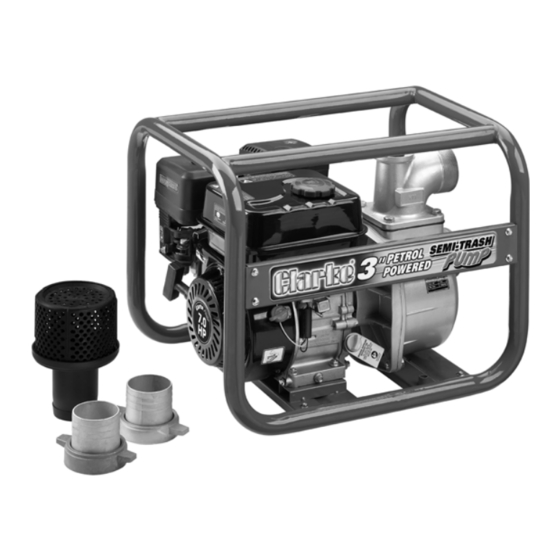
- Page 1 ENGINE DRIVEN SEMI TRASH 3” PUMP MODEL NO: PS75 PART NO: 7230160 OPERATION & MAINTENANCE INSTRUCTIONS LS0817 - ISS 1...
- Page 2 2 x 3" BSP Locking Rings 1 Plastic x Inlet Strainer (in two pieces) with 3" 3 x Hose Clips Hose adaptor Speak to your Clarke dealer If items are missing or damaged. Parts & Service: 020 8988 7400 / E-mail: Parts@clarkeinternational.com or Service@clarkeinternational.com...
-
Page 3: General Safety Rules
GENERAL SAFETY RULES WARNING: WHEN USING PUMPS, ALWAYS FOLLOW BASIC SAFETY PRECAUTIONS TO REDUCE THE RISK OF FIRE, ELECTRIC SHOCK AND PERSONAL INJURY. READ ALL INSTRUCTIONS BEFORE YOU OPERATE THIS PUMP AND SAVE THEM FOR FUTURE REFERENCE. 1. ALWAYS obey all safety precautions for the handling of fuel. 2. -
Page 4: General Safety In The Workplace
5. Always wear safety glasses. (Everyday glasses are not safety glasses). CARE OF PUMPS 1. The Clarke service department must replace damaged components. 2. Always examine the pump for damage that can effect the operation of the pump. Repair any damaged parts. - Page 5 ASSEMBLY INSTALL THE SUCTION HOSE 1. Put the rubber washer into the adaptor. • Make sure that it is seated correctly. 2. Screw the adaptor onto the pump securely. 3. Slide the hose on to the adaptor and lock in position with the jubilee clip supplied.
- Page 6 INSTALL THE DISCHARGE HOSE 1. Put the rubber washer into the adaptor. • Make sure that it is seated correctly. 2. Screw the adaptor onto the pump securely. 3. Slide the hose on to the adaptor and lock in position with the jubilee clip supplied.
-
Page 7: Before Use
BEFORE USE PUMP PLACEMENT For best pump performance, place the pump near the water level, and use hoses that are no longer than necessary. That will enable the pump to produce the greatest output with the least self-priming time. As head (pumping height) increases, pump output decreases. The length, type, and size of the suction and discharge hoses can also significantly affect pump output. -
Page 8: Check The Engine Oil Level
• Oil capacity (See page 20). • We recommend you use SAE15W40 oil in this pump. available from your Clarke dealer. 5. Replace the oil filler cap. Parts & Service: 020 8988 7400 / E-mail: Parts@clarkeinternational.com or Service@clarkeinternational.com... - Page 9 ADD FUEL WARNING: REFUEL IN A VENTILATED AREA, AWAY FROM SOURCES OF IGNITION. WARNING: IF THE ENGINE IS HOT, LET IT COOL BEFORE REFUELING. WARNING: KEEP FUEL OUT OF THE REACH OF CHILDREN. RECOMMENDED FUEL Only use unleaded petrol. 1. Remove the fuel tank cap. •...
-
Page 10: Operation
OPERATION WARNING: WHEN YOU OPERATE THE PUMP, THE EXHAUST MUFFLER WILL BE VERY HOT. WARNING: DO NOT OPERATE THE ENGINE IN A CLOSED SPACE, MAKE SURE THAT THERE IS SUFFICIENT AIRFLOW AROUND THE PUMP. PRIME THE PUMP 1. The pump MUST be primed before 2. -
Page 11: Start The Engine
START THE ENGINE 1. Set the fuel valve to the ON position. 2. To start a cold engine, move the choke lever to the ‘OFF’ position. • To restart a warm engine, leave the choke lever in the ‘ON’ position. 3. - Page 12 5. Pull the starting handle lightly until you start to feel resistance. Then pull up and away suddenly to start the engine. NOTE: You might need to do this more than once. WARNING: WHEN THE PUMP HAS STARTED, RELEASE THE STARTING HANDLE SLOWLY TO PREVENT INJURY/DAMAGE AS IT RETURNS.
-
Page 13: Shut Down The Pump
SHUT DOWN THE PUMP To stop the pump in an emergency, set the engine switch to ‘OFF’. 1. Use the throttle lever to decrease engine speed to minimum. 2. Set the engine switch to “OFF”. 3. Turn the fuel valve to “OFF”. AFTER USE 1. -
Page 14: Maintenance
MAINTENANCE CLEARING BLOCKAGES 1. Remove the hoses and adaptors from the pump. 2. Remove the four bolts shown in the picture. 3. Remove the front cover. 4. Clear debris and clean the inner parts using clean water. 5. Replace the front cover and secure using the four bolts removed in step 2. -
Page 15: Changing The Engine Oil
• Fill until the oil touches the threads in the oil fill tube. • Oil capacity (0.6l). • We recommend that you use SAE15W40 oil in this pump available from your Clarke dealer. 6. Replace the oil filler cap/dipstick. ENVIRONMENTAL PROTECTION One of the most damaging sources of pollution is oil, do not throw away or pour it down drains. -
Page 16: Changing The Spark Plug
CHANGING THE SPARK PLUG Replace the spark plug after the first month or every 50 hours of use. 1. Remove the spark plug cap from the spark plug. 2. Use the spark plug spanner supplied to remove the spark plug. 3. -
Page 17: Changing The Air Filter
CHANGING THE AIR FILTER Clean the air filter after 50 hours of operation (or more often in unusually dusty conditions) as follows. 1. Unscrew the wingnut and lift off the air filter cover. 2. Remove the wingnut that holds the air filter in position. 3. -
Page 18: Troubleshooting
If a spark is present but engine will not start, consult your Clarke dealer. The engine stops No fuel in tank. Add fuel to the tank. -
Page 19: Environmental Protection
Damaged impeller. Disassemble the pump and replace the impeller. If you cannot correct the fault, speak to your local dealer or the Clarke International service department. ENVIRONMENTAL PROTECTION At the end of its working life, do not discard this pump or its components with general household waste. -
Page 20: Specification
SPECIFICATION Item Spec pump dimensions (L x W x H) 530 x 450 x 485 mm pump Weight (kgs) 24.3 kg Water classification Dirty / Clean (NOT SEWAGE) Max solids in suspension 15 mm Inlet/Outlet Size 3” BSP Maximum Flow 750l/min (45m /h) max Max Head... -
Page 21: Exploded Diagrams And Parts List
EXPLODED DIAGRAMS AND PARTS LIST FIG 1 - HEAD SUBASSEMBLY, CYLINDER / PLUG,SPARK NUMBER DESCRIPTION PART NUMBER GASKET, CYLINDER HEAD ZG12131Z530320 CYLINDER HEAD COVER SUBASSEMBLY, ZG12410Z440210 CYLINDER HEAD COVER GASKET, ZG12004Z440210 BREATHER TUBE, ZG17004Z440110 BOLT ZG90001061201 STUD ZG90204Z010310 STUD ZG90203Z010110 ZG90502111400 CYLINDER HEAD BOLT, ZG12003Z010110... - Page 22 FIG 2 - CRANKCASE. / GEAR ASSEMBLY, GOVERNOR NUMBER DESCRIPTION PART NUMBER CRANKCASE SUBASSEMBLY. ZG11310Z530410 ENGINE OIL SENSOR, ZG37060Z010110 GOVERNOR GEAR ASSEMBLY, ZG16400Z010110 GOVERNOR ARM, ZG16061Z010110 DRAIN PLUG BOLT, ZG11007Z010110 WASHER ZG90408Z010110 BEARING ZG905470205CL OIL SEAL, ZG90682Z300110 WASHER ZG90408Z010210 ZG90501Z010110 BOLT ZG90001061401 Parts &...
- Page 23 FIG 3 - COVER SUBASSEMBLY, CRANKCASE NUMBER DESCRIPTION PART NUMBER CRANKCASE COVER, ZG11411Z440210 BEARING ZG905470205CL OIL SEAL, ZG90682Z300110 CRANKCASE GASKET, ZG11001Z440110 ZG90502081200 OIL DIPSTICK SUBASSEMBLY, ZG15010Z010120 ENGINE OIL PLUG SUBASSEMBLY, ZG15030Z010120 BOLT ZG90001083201 Parts & Service: 020 8988 7400 / E-mail: Parts@clarkeinternational.com or Service@clarkeinternational.com...
- Page 24 FIG 4 - VALVE TRAIN / CAMSHAFT SUBASSEMBLY NUMBER DESCRIPTION PART NUMBER CAMSHAFT ASSEMBLY. ZG14200Z530110 EXHAUST VALVE, ZG12121Z010120 INTAKE VALVE, ZG12111Z010110 VALVE SPRING SEAT, ZG12112Z010110 EXHAUST VALVE RETAINER ZG12107Z010110 VALVE R0TATOR, ZG12104Z010110 SEAL GUIDE, ZG12101Z020110 VALVE TAPPET, ZG14081Z040110 VALVE LIFTER, ZG14071Z440110 LIFTER STOPPER PLATE SUBASSEMBLY, ZG14090Z010110...
- Page 25 FIG 5 - OIL RING SET / CRANKSHAFT CONNETING ROD NUMBER DESCRIPTION PART NUMBER PISTON PIN CLIP, ZG13122Z010110 PISTON ZG13111Z140220 PISTON PIN, ZG13121Z010110 CONNECTING ROD, ZG13010Z440210 THE FIRST RING, ZG13201Z140210 THE SECOND RING, ZG13202Z140210 OIL RING SET, ZG13210Z140220 FIG 6 - CRANKSHAFT CONNETING ROD NUMBER DESCRIPTION PART NUMBER...
- Page 26 FIG 7 - RECOIL STARTER NUMBER DESCRIPTION PART NUMBER RECOIL STARTER ASSEMBLY, ZG28200Z440110 BOLT ZG90001060803 RECOIL STARTER REEL END CAP ZG90722Z300110 Parts & Service: 020 8988 7400 / E-mail: Parts@clarkeinternational.com or Service@clarkeinternational.com...
- Page 27 FIG 8 - SHROUD / LOWER SHIELD NUMBER DESCRIPTION PART NUMBER SHROUD ZG28110Z010410 CYLINDER BODY SHROUD, ZG19304Z010110 LOWER SHIELD, ZG19340Z010120 OIL PROTECTOR, ZG37050Z010210 SWITCH SUBASSEMBLY, STOP ENGINE ZG35540Z060120 BOLT ZG90001061001 BOLT ZG90001061001 COLLAR ZG90740Z010110 BOLT ZG90001061601 BOLT ZG90001061201 Parts & Service: 020 8988 7400 / E-mail: Parts@clarkeinternational.com or Service@clarkeinternational.com...
- Page 28 FIG 9 - CARBURETOR ASSEMBLY NUMBER DESCRIPTION PART NUMBER CARBURETOR ASSEMBLY. ZG16100Z530410 AIR CLEANER GASKET, ZG17001Z010210 CARBURETOR GASKET, ZG16001Z010110 CARBURETOR INSULATOR PLATE, ZG16003Z010110 CARBURETOR INSULATOR GASKET, ZG16002Z050110 Parts & Service: 020 8988 7400 / E-mail: Parts@clarkeinternational.com or Service@clarkeinternational.com...
- Page 29 FIG 10 - AIR CLEANER NUMBER DESCRIPTION PART NUMBER ZG903050600 AIR CLEANER, ZG17100Z440220 FIG 11 - FLYWHEEL / IMPELLER / STARTER PULLEY / IGNITION COIL NUMBER DESCRIPTION PART NUMBER FLYWHEEL NUT, ZG13501Z010110 Parts & Service: 020 8988 7400 / E-mail: Parts@clarkeinternational.com or Service@clarkeinternational.com...
- Page 30 STARTER PULLEY, ZG28002Z260210 IMPELLER ZG19352Z440110 FLYWHEEL SUBASSEMBLY ZG13510Z440110 BOLT ZG90001062501 IGNITION COIL ZG30400Z300110 FIG 12 - MUFFLER ASSEMBLY NUMBER DESCRIPTION PART NUMBER EXHAUST OUTLET GASKET, ZG18001Z440110 ZG90303080031 MUFFLER ASSEMBLY ZG18100Z442310H699 Parts & Service: 020 8988 7400 / E-mail: Parts@clarkeinternational.com or Service@clarkeinternational.com...
- Page 31 FIG 13 - FUEL TANK ASSEMBLY NUMBER DESCRIPTION PART NUMBER FUEL TANK, ZG16620Z440510 FUEL STRAINER? ZG16652Z010710 FUEL TANK COVER, ZG16730Z440320 FUEL TANK OIL OUTLET SUBASSEMBLY, ZG16680Z010110 CLAMP ZG90685Z030220 TUBE, FUEL ZG90686Z010710 BOLT ZG90001063001 ZG90305060031 RUBBER JACKET, ZG30431Z010110 ZG16804Z440210 CLAMP ZG90685Z030410 ZG15150Z010510 Parts &...
- Page 32 FIG 14 - THROTTLE CONTROL ASSEMBLY NUMBER DESCRIPTION PART NUMBER THROTTLE CONTROL ASSEMBLY, ZG16520Z010420 BOLT ZG90001061001 GOVERNOR SPRING, ZG16063Z050120 GOVERNEOR ROD, ZG16062Z010110 THROTTLE VALVE RETURNING ZG16012Z010110 SPRING, GOVERNOR SUPPORT BOLT, ZG16072Z010110 ZG90305060031 GOVERNOR SUPPORT 16070-Z010110-GMQGZ80-45-30 SUBASSEMBLY, Parts & Service: 020 8988 7400 / E-mail: Parts@clarkeinternational.com or Service@clarkeinternational.com...
- Page 33 FIG 15 - WATER PUMP ASSEMBLY NUMBER DESCRIPTION PART NUMBER HOSE HOOP ASSEMBLY, ZGGMQGZ804525F6801 FILTER COVER, ZGGMQGZ804525F6802 FILTER ZGGMQGZ804525F6803 BOLT ZG90001082501F6804 WASHER ZGGMQGZ804525F6805 WASHER ZG90408080001F6806 WATER INLET, ZGGMQGZ804525F6810 INLET WATER GASKET? ZGGMQGZ804525F6811 THREAD PLUG, ZGGMQGZ804525F6812 SCREW PLUG WASHER, ZGGMQGZ804525F6813 WATER OUTLET ZGGMQGZ804525F6814 OUTLET GASKET ZGGMQGZ804525F6815...
- Page 34 ZGGMQGZ804525F6824 PORCELAIN SEAL, ZGGMQGZ804525F6825 MECHANISM SEAL ASSEMBLY, ZGGMQGZ804525F6826 WATER PUMP JOINT, ZGGMQGZ804525F6827 WASHER ZGGMQGZ804525F6828 BOLT ZGGMQGZ804525F6829 WATER PUMP ASSEMBLY, ZGGMQGZ804525F6830 FIG 16 - ENGINE FRAME ASSEMBLY NUMBER DESCRIPTION PART NUMBER ENGINE FRAME ASSEMBLY, ZG51100V010110H700 DECORATIVE FRAME ZG210GM720423-0002 ENGINE FRAME SHOCK ZG51014HY450110GMQGZ804525 ABSORPTION SEAT, BOLT...
-
Page 35: Declaration Of Conformity
DECLARATION OF CONFORMITY Parts & Service: 020 8988 7400 / E-mail: Parts@clarkeinternational.com or Service@clarkeinternational.com...
Need help?
Do you have a question about the PS75 and is the answer not in the manual?
Questions and answers