Table of Contents
Advertisement
Quick Links
Advertisement
Table of Contents

Related Manuals for LevelOne DSS-1000


Summary of Contents for LevelOne DSS-1000
- Page 1 DSS-1000 User Manual For V1.02.09 Firmware Ver. 2014/10/03...
- Page 2 DSS-1000 User Manual Legal Notice Disclaimer The information contained in this document is intended for general information purposes. The manufacturer shall not be liable for errors contained herein or for incidental or consequential damages arising from the furnishing, performance, or use of this manual....
- Page 3 DSS-1000 User Manual Regulatory Compliance Information Federal Communications Commission Statement This equipment has been tested and found to comply with the limits for a Class B digital device, pursuant to Part 15 of the FCC Rules. These limits are designed to provide reasonable protection against harmful interference in a residential installation.
- Page 4 DSS-1000 User Manual About This Manual Target Audience This manual is intended for System Administrators who are responsible for installing and setting up video surveillance system as well as End Users who will be operating DSS on a daily basis. System Administrators are expected to know the fundamentals of IP surveillance system integration and to own the administrative privileges to install and configure all the devices.
-
Page 5: Table Of Contents
Connecting to Local Display ..............17 Local Display via HDMI Connection .......... 17 Local Display via Composite Connection ........17 Connecting the Cameras................. 18 1.3 Accessing DSS-1000 ............ 19 Local Access ................19 Remote Access ................. 19 Local vs. Remote Access ............19 1.4 Device Maintenance ............ - Page 6 DSS-1000 User Manual 2.2 The Live View Screen ..........27 The Menu Panel ..................28 Changing the Layout ................29 Viewing Channels in Full Screen............30 Viewing Channels by Patrol ..............31 Repositioning Channels ................31 2.3 The Login Screen ............33 Using the On-Screen Keyboard ..............
- Page 7 Copying Event Schedule Settings ............68 2.10 Rebooting the Device ..........69 Chapter 3: Remote Management ........70 3.1 Accessing DSS-1000 Remotely ........71 How to Access DSS-1000?............... 71 Accessing From a Network with DHCP Server......71 Accessing From a Network without DHCP Server ..... 73 The Login Screen ..................
- Page 8 DSS-1000 User Manual 3.3 The Setup Screen ............91 3.4 Configuring the System Settings ........ 92 System Information ................92 Date and Time ..................93 Automatically Set the Date and Time ........93 Manually Change the Date and Time ........93 Sync Date and Time with NTP Server ........
- Page 9 DSS-1000 User Manual Deleting Beep Trigger ................122 Copying Event Schedule Settings ............123 3.9 System Maintenance ..........124 Upgrading the Firmware ..............124 Saving Backup Settings ................ 125 Restoring Backed Up Settings .............. 126 Troubleshooting ..................127 3.10 Managing the System Log ......... 128 3.11 Rebooting the Device ..........
-
Page 10: Chapter 1: Hardware Overview
Introduction: Describes the package contents, device overview, and the connection architecture. Connecting Devices: Describes how to connect DSS-1000 to other devices and how to use the bundled accessories. Accessing the Device: Describes the different methods on how to access the device... -
Page 11: Introduction
DSS-1000 User Manual 1.1 Introduction Package Contents DSS-1000 Screw Packs x 2 Cable Straps Mounting Bracket Power Adaptor Terminal Block Quick Installation Guide... -
Page 12: Device Overview
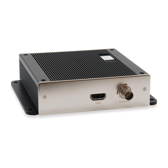
The LED turns off and lights up again when the restoration completes and DSS-1000 is ready for use. Use to restore DSS-1000 to its factory default setting. Reset Button / NTSC and PAL Switch Use to switch between NTSC and PAL functions. -
Page 13: System Requirements
DSS-1000 conforms to the display standard of composite and 1080p HDMI monitors. Therefore, to reserve as much computing power for DSS-1000 as possible, only up to 2 megapixels H.264 video stream can be displayed on the Local Live View. A black screen with a message will appear for channels using other codecs or those with higher resolution. - Page 14 @ 30 fps (1920 x 1080) 9 channels 9 channels only @ 12 fps @ 10 fps NOTE: Regardless of the configured frame rate of a camera video stream, DSS-1000 automatically adjusts the frame rate according to the table above.
-
Page 16: Connecting Devices
NOTE: This step may be skipped if a Power-over-Ethernet (PoE) switch or injector will be connected to DSS-1000. Connect a monitor to DSS-1000 via HDMI or Composite port connection (see Connecting to Local Display on page 17). 3. Connect a USB mouse. -
Page 17: Preparing The Power Adaptor
Preparing the Power Adaptor In case of using a non-PoE Ethernet switch, use the bundled power adaptor to directly connect DSS-1000 to a power outlet. The power adaptor must be connected to the supplied terminal block before use. To do this, follow the procedures below: 1. -
Page 18: Connecting To Local Display
These display outputs can be referred to as the local display or the local client. Local Display via HDMI Connection Connect an HDMI monitor (1080p) to the HDMI port of DSS-1000 using an HDMI cable (not included in the package). -
Page 19: Connecting The Cameras
DSS-1000 User Manual Connecting the Cameras DSS-1000 can decode up to 16 IP cameras or video encoders and display the videos through an HDMI (1080p) or composite monitor or display remotely via PC or a mobile client. To connect a camera, do the following: 1. -
Page 20: Accessing Dss-1000
DSS-1000 User Manual 1.3 Accessing DSS-1000 DSS-1000 can be accessed and managed in two ways: via Local access or Remote access. Local Access A monitor that is directly connected to DSS-1000 via the HDMI or Composite port is considered Local Access by a Local Client. Users can view the videos from the camera and manage network configurations right through the monitor. -
Page 21: Device Maintenance
Default LED lights on and off several times until it completely lights up to indicate reset is complete. Switching Between NTSC and PAL Mode When DSS-1000 is powered on, briefly press the NTSC and PAL switch (also the Reset button) to switch between NTSC and PAL mode. -
Page 22: Chapter 2: Local Management
ECD-1000 User Manual Chapter 2: Local Management This chapter describes DSS-1000 operation and management on the Local Client side. It contains the following topics: Accessing for the First Time: Describes the setup procedures involve when accessing DSS-1000 for the first time. This includes changing DSS-1000 IP address and adding the cameras.... -
Page 23: Accessing For The First Time
Network Disconnected Cable is unplugged Connected DSS-1000 comes with a default static IP address of 192.168.0.200. If your network has a DHCP server, DSS-1000 will automatically switch the connection type to DHCP and be assigned an IP address. Use the USB mouse to navigate through the user interface. Move the mouse cursor towards... -
Page 24: Quick Setup
Change the IP Address on Network without DHCP Server Remember that DSS-1000 must be on the same network segment as the cameras. In case you need to change the IP address of DSS-1000, follow the procedures below on how to do this. -
Page 25: Step 3: Add Cameras
DSS-1000 User Manual 4. Click Save. 5. When LAN showsActivated“”, the IP address configuration is complete. Step 3: Add Cameras 1. On the Setup screen, click Camera > Search Cameras. NOTE: To add cameras by IP address or connect to camera via RTSP protocol, see Adding Cameras on page 53. - Page 26 Modify these values as needed. NOTE: DSS-1000 supports third-party cameras. To validate specific camera models that can be integrated, visit our website. 3. Click one or more camera model(s). Selected cameras are displayed in orange.
- Page 27 DSS-1000 User Manual 5. Click to close the Setup screen. The Live View screen appears with the added cameras. By default, information such as the camera name, IP address, etc. are displayed on the local display. For security purposes, these information may be hidden, see Local Display page 47 for more information.
-
Page 28: The Live View Screen
These triggers are based on the events configured on the camera side. Connection Error Indicates the camera is disconnected from the network. System Date and The system date and time. Time DSS-1000 IP Address The IP address of DSS-1000. -
Page 29: The Menu Panel
DSS-1000 User Manual The Menu Panel Move the mouse cursor towards the bottom of the screen to display the Menu Panel. From the Menu Panel, users can modify the channel layout, start viewing channels on patrol, stretch image, reposition the channels, and access the Setup screen. -
Page 30: Changing The Layout
DSS-1000 User Manual Changing the Layout By default, the local Live View is displayed with a 9-channel layout. The layout can be changed into a 1-channel, 2-channel, 1+7-channel display, etc. Available layout varies depending on current channel mode (see Module on page 44). -
Page 31: Viewing Channels In Full Screen
DSS-1000 User Manual Layout 2+4 Layout 2+8 Click to display 8 Click to display 10 channels at a time on a 2+4 channels at a time on a 2+8 layout. layout. To view succeeding channels, click the layout icon again. For example, if viewing on a... -
Page 32: Viewing Channels By Patrol
DSS-1000 User Manual Viewing Channels by Patrol Instead of viewing all channels at the same time, users may want to view one channel in full screen and scroll through all the channels at a time. To do this, follow the procedures below: 1. - Page 33 DSS-1000 User Manual Repositioned Channels To reset the default channel position, click...
-
Page 34: The Login Screen
DSS-1000 User Manual 2.3 The Login Screen The Login screen appears before users can access the PTZ Control Panel and the Setup Page. When prompted to login, enter the default Account and Password using the on-screen keyboard. For security purposes, it is recommended to modify the account name and password through a remote client computer. -
Page 35: Using The On-Screen Keyboard
DSS-1000 User Manual Using the On-Screen Keyboard The on-screen keyboard allows users to enter text without using a physical computer keyboard. The on-screen keyboard appears when users click on fields that require character or numeric input, such as account name, password, etc. Using the mouse, click the keys on the on-screen keyboard to enter characters or numbers. -
Page 36: Using The Ptz Control Panel
DSS-1000 User Manual 2.4 Using the PTZ Control Panel You can pan, tilt and zoom PTZ cameras locally using the PTZ Control Panel, as well as create preset points and start tour. To display the PTZ Control Panel, move the mouse over the bottom of the screen to display the Menu Panel, then click . - Page 37 DSS-1000 User Manual Item Description Tilt Speed Drag the slider to adjust the tilt speed; 1 (slowest) to 5 (fastest). Zoom Speed Drag the slider to adjust the zoom speed; 1 (slowest) to 5 (fastest). Zoom Control Click the icons to zoom in or zoom out the camera view.
-
Page 38: Setting Preset Points
A preset point is a user-defined area where the camera zooms in. Up to 32 preset points can be configured on DSS-1000. When preset points are created on DSS-1000, they are automatically synced on the camera side, and vice versa. - Page 39 DSS-1000 User Manual How to Create / Modify Preset Points 1. On the Live View screen, move the mouse over the bottom of the screen to display the Menu Panel, then click . You must login as an administrator to have PTZ control access (see 2.3 The Login Screen...
-
Page 40: Setting Tours
Several preset points can be grouped into a “Tour”which directs the camera to cycle through the series of preset points at specific interval time. Up to 32 tours can be set on DSS-1000. The tour configuration is saved only on DSS-1000, not on the camera side. - Page 41 To create tours, make sure one or more preset points have already been created. The tour configuration on DSS-1000 is not synced with the tour configuration on the camera side. 1. On the Live View screen, move the mouse over the bottom of the screen to display the Menu Panel, then click .
- Page 42 DSS-1000 User Manual 6. Repeat steps 4 to 5 to add more preset points to the tour. TIP: Use the arrow keys to change the order sequence of preset points. Or, to remove a preset point from the tour, click 7.
-
Page 43: Accessing The Setup Screen
DSS-1000 User Manual 2.5 Accessing the Setup Screen The Setup screen allows users to configure the system and network settings and add or delete cameras for viewing. Users must login with an administrator account first to access the Setup screen. -
Page 44: Configuring System Settings
System Information On the Setup screen, click System. The system information is displayed. System Name: Name assigned to DSS-1000; can be modified. To modify the System Name, click the box and use the on-screen keyboard to enter the characters. ... -
Page 45: Module
DSS-1000 User Manual Module The Module page allows you to select the maximum number of cameras that you can view through DSS-1000. Options are: 4-channel, 9-channel (default mode), 12-channel, and 16-channel. To ensure video stream performance, take note of the Decoding Limitation on page 13. -
Page 46: Manually Change The Date And Time
DSS-1000 User Manual changes according to the current date and time of the time zone. 3. If applicable, check the Enable Daylight Saving Time box. Note that this box becomes enabled only if the Daylight saving time can be applied to the selected time zone. -
Page 47: Sync Date And Time With Ntp Server
DSS-1000 User Manual Sync Date and Time with NTP Server 1. On the Setup screen, click System > Date and Time. 2. On NTP Server, type the URL address of the NTP server. 3. Click Apply. A message will appear to confirm if synchronization is successful. -
Page 48: Mouse
DSS-1000 User Manual Mouse Click System > Mouse. Click-” “to reduce mouse cursor+”to speedincreaseor “onethenotchspeedatatime. and - ”holdor+” ““to continuously Click reduce increase speed. Local Display The Local Display allows users to show or hide information, such as the IP address, system date and time, or event trigger icons, on the Live View screen. -
Page 49: Local Audio Out
DSS-1000 User Manual Show system time: If checked, the system date and time is displayed on the bottom of the Live View screen. Show system IP address: If checked, the system IP address is displayed on the bottom of the Live View screen.... -
Page 50: Configuring Network Settings
DSS-1000 User Manual 2.7 Configuring Network Settings Viewing the Network Information On the Setup screen, click Network. The network information, such as the Hardware Address (MAC address), Speed, Connection Type, IP Address, Subnet Mask, Gateway, DNS Setting, and Primary and... -
Page 51: Configuring The Network Connection
Subnet Mask, Gateway, etc. Note that the IP address must be unique for each device on the network. By default, DSS-1000 has a default IP of 192.168.0.200 and subnet mask of 255.255.255.0. Users may need to change the default IP and subnet mask to ensure DSS-1000 belongs to the same network segment as the cameras.... -
Page 52: Obtaining The Ip Address Automatically
3. Leave the default DNS Setting as Auto“” . 4. Click Save. Connection is complete when LAN showsActivated“” . Configuring Port Mapping By default, DSS-1000 port number is 80. To change this value, click Network > Port Mapping on the Setup screen. -
Page 53: Configuring The Cameras
Adding Cameras on page 53. Camera Settings: Displays the camera video streaming properties, such as Channel ID, Resolution, Encoder, etc. These properties can be modified on DSS-1000 and will also take effect on the camera side. See Modifying Camera Settings... -
Page 54: Adding Cameras
4, 9, 12 or 16 cameras to connect to DSS-1000. The maximum number of cameras to be added varies depending on the selected module (see Module on page 44). - Page 55 In Use: The camera is already added to DSS-1000 for live viewing. 6. Click Add to add the selected cameras to DSS-1000 for live viewing. The cameras are then displayed on the Camera List panel. 7. Click to close the Setup screen. The Live View screen displays the live view of the...
-
Page 56: Adding Cameras Manually
DSS-1000 User Manual Adding Cameras Manually In case of adding a camera from outside the local area network or over WAN, use the add camera manually function. You need to know the IP address, HTTP port, User Name and Password of the camera you want to connect to. - Page 57 DSS-1000 User Manual 5. Click Get Camera Settings. DSS-1000 connects and retrieves the camera settings. At this point, nothing is shown on the Display window yet. 6. Click Save. Once camera settings are saved, the camera Live View is shown on the Display window.
-
Page 58: Adding Onvif-Compliant Cameras Manually
4. Enter the IP Address, HTTP Port (by default 80), Account and Password of the camera you want to connect to. 5. Click Get Camera Settings. DSS-1000 connects and retrieves the camera settings. At this point, nothing is shown on the Display window yet. -
Page 59: Adding Cameras Manually Via Rtsp
DSS-1000 User Manual TIP: Use the Duplicate button to add another camera with almost similar camera settings to another channel, see Duplicating Cameras on page 59. Adding Cameras Manually via RTSP In case you want to add cameras via Real Time Streaming Protocol (RTSP), use the Add Camera Manually (RTSP) function. - Page 60 DSS-1000 User Manual TIP: If you do not know the URI of the camera, click to select from the most common manufacturers on the list. Once a manufacturer is selected, its URI is filled up on the field. If the predefined URI does not work, check the camera specifications for details.
- Page 61 DSS-1000 User Manual 2. Available channels are shown under To. Check the box(es) of the channel(s) to copy the camera settings to. 3. Click Duplicate.
-
Page 62: Modifying Camera Settings
HTTP Port (port used by remote IE clients), User Name and Password, as needed. NOTE: The Name is the camera name displayed on DSS-1000. This name is not saved or shown on the camera side. The maximum length is 32 alphanumeric characters, symbols are not allowed. - Page 63 Network Video Recorder (NVR) recording purposes and stream 2 or Channel ID 2 with basic quality for live viewing on the NVR and DSS-1000. Once the Channel ID is selected, the succeeding camera properties, such as encoder, resolution, etc., change according to the compression settings of the...
- Page 64 GOP is changed- frameto“1 perI 5 seconds”, th one I-frame, followed by 149 P-frames. In case of the static scenes, long GOP can further minimize the bandwidth and storage consumption. 6. When done, click Save. The camera properties are saved and DSS-1000 restarts the connection.
-
Page 65: Reconnecting Cameras
DSS-1000 User Manual Reconnecting Cameras If there is a need to refresh the camera connection, click Reconnect All. All the cameras will be reconnected. NOTE: All video streams will be lost for a few seconds until the reconnection is finished. -
Page 66: Managing Network Loss Event
DSS-1000 User Manual 2.9 Managing Network Loss Event When a camera or a DSS-1000 suddenly disconnects from the network, DSS-1000 will trigger a network or video loss notification icon on the Live View channel window and will beep. By default, the trigger is enabled for 24 hours a day and 7 days a week. However, the beep sound must be enabled and configured separately. - Page 67 DSS-1000 User Manual 4. Drag the mouse over the time table to select the day and time period. 5. When done, click Save. TIP: Instead of manually modifying the event trigger on all cameras, users can copy the schedule to other channels. See Copying Event Schedule Settings on page 68.
-
Page 68: Enabling Beep Sound Trigger
DSS-1000 User Manual Enabling Beep Sound Trigger To enable the beep sound when a camera is disconnected from the network or when an encoder loses its video source, do the following: 1. On the Setup screen, click Event. 2. Click Network Loss or Video Loss, and then click Set. -
Page 69: Copying Event Schedule Settings
DSS-1000 User Manual 6. Click Save to save the configurations. DSS-1000 will demonstrate and emit the beep sound as configured. Copying Event Schedule Settings Instead of manually modifying the event schedule and beep settings on all cameras one by one, users can copy the settings to other channels. -
Page 70: Rebooting The Device
2.10 Rebooting the Device 1. On the Setup screen, click Power. 2. Click Reboot. 3. When the confirmation message appears, click OK to restart. NOTE: All video streams will be lost for a few seconds until DSS-1000 completes the reboot process. -
Page 71: Chapter 3: Remote Management
This chapter describes DSS-1000 operation and management on a Remote Client side. It contains the following topics: Accessing the Device: Describes the setup procedures involve when accessing DSS-1000 for the first time through a computer on the network. This includes changing DSS-1000 IP address and adding the cameras. ... -
Page 72: Accessing Dss-1000 Remotely
In most cases, it is recommended to perform the initial configurations, before DSS-1000 is even mounted to its location, using local access. This is because of the limitation of DSS-1000 to decode some video resolution and compression. If monitoring will be mainly done on a local display, it is recommended to directly test and view the camera live view on the local display to ensure the video stream properties are supported for local display. - Page 73 From IP Utility (downloaded from the website), click the IP address of DSS-1000 to open the user interface on the web browser. If you already know the IP address of DSS-1000, open the web browser and directly type the IP address on the address bar....
-
Page 74: Accessing From A Network Without Dhcp Server
The default IP address of DSS-1000 is 192.168.0.200. If the network does not have a DHCP server, then this is the IP address of DSS-1000, whereas the default port number is 80. Take note that the computer must be within the same network segment. For example, the computer must have an IP address of 192.168.0.X (where X is any number between 1 ~ 255, except... -
Page 75: The Login Screen
Check to skip the login page and go directly to the Live View screen every time the user logs in from the current computer. This feature takes effect on the succeeding log in. NOTE: This can be a security risk for any other user will be able to access DSS-1000. -
Page 76: The Setup Wizard
DSS-1000 User Manual The Setup Wizard When accessing DSS-1000 for the first time on a client computer, the Setup Wizard appears to facilitate easy camera connection. All settings can still be modified in the Setup screen. 1. Click Next. 2. Set the date and time by one of the following options: ... - Page 77 If you want to add camera from other manufacturers or the camera has different account and password, modify these values as needed. Then, click Search to search for cameras. NOTE: DSS-1000 supports third-party cameras. To validate specific camera models that can be integrated, visit our website.
- Page 78 DSS-1000 User Manual 6. The list of cameras connected on the network appears. Click on a camera to select it. By default, you can select up to 9 cameras to add. Selected cameras are highlighted in orange. 7. Click Next to continue.
-
Page 79: The Live View Page
Description Camera List Displays the channel number and camera name of the cameras connected to DSS-1000. Drag a channel to a window on the Live View display area to view the video stream. Or, double-click All Cameras to automatically view all cameras on the list to the Live View display area. - Page 80 Click to sync the local display according to the remote client display. Your user account The IP address of DSS-1000 Click to view the firmware version. The system date and time. Click the date and time to access the Date and Time menu.
-
Page 81: Viewing The Cameras
Double-click All Cameras to view all cameras on the Live View display area. NOTE: DSS-1000 does not save the displayed channel settings; so every time users access DSS-1000, the Live View display area is empty and cameras must be added to the Live View display area again. - Page 82 DSS-1000 User Manual Viewing Channels in Full Screen Double-click a channel to view the channel in full screen. Double-click again to switch back to the previous layout. Zooming In With the mouse icon over the channel window, scroll the mouse wheel up or down to zoom in or zoom out the image.
-
Page 83: Changing The Window Layout
DSS-1000 User Manual Changing the Window Layout By default, the Live View is displayed with a 9-channel layout. The layout can be changed into a 1-channel, 2-channel, 1+7-channel display, etc. Layout 1 Layout 2 Layout 4 Click to display one... -
Page 84: Patrolling Channels
DSS-1000 User Manual Layout 2+4 Layout 2+8 Click to display 6 Click to display 10 channels at a time on a 2+4 channels at a time on a 2+8 layout. layout. To view succeeding channels, use the icon. For example, if viewing on a 2-channel layout, and you want to view the next 2 channels, click . -
Page 85: Syncing Remote And Local Live View Display
DSS-1000 User Manual Syncing Remote and Local Live View Display The displayed cameras and window layout on the remote client and local client can be synced. Click to sync the Live View based on the local client display. So instead of dragging... -
Page 86: Using Optical / Digital Ptz
DSS-1000 User Manual Using Optical / Digital PTZ PTZ and zoom cameras have the option to toggle between optical and digital PTZ. Non-PTZ and non-zoom cameras can still have digital PTZ functions when viewed on remote clients. For PTZ and zoom cameras, right-click on the channel window and click Digital PTZ or Optical PTZ to toggle between optical and digital PTZ. -
Page 87: Taking Snapshots
DSS-1000 User Manual How to Use Digital PTZ Digital PTZ can be done on the channel window and on full-screen view. For PTZ and zoom cameras, right-click the mouse button and toggle to Digital PTZ first. 1. On the Live View, select the camera to highlight the channel window. -
Page 88: Using The Ptz Control Panel
DSS-1000 User Manual Using the PTZ Control Panel Use the PTZ Control Panel to pan, tilt, and zoom the camera. To display the PTZ Control Panel, click PTZ from the left panel menu. TIP: Move the mouse over the icon to display the function name. -
Page 89: Viewing By Preset Point And Tour
DSS-1000 User Manual Viewing by Preset Point and Tour NOTE: The Preset Point Panel is available only when PTZ and zoom cameras are selected. For other cameras, the Preset Point Panel appears blank. PTZ and zoom cameras can have up to 32 preset points and 32 tours configured on DSS- 1000. -
Page 90: Using The Toolbar
Decode I-frame / Auto Drop Frame: Select Decode I-frame to save computing power. With this function, DSS-1000 decodes only the I-frames, so the frame rate of each channel becomes 1 fps. This function is useful when using a computer which is also used for other applications.... - Page 91 DSS-1000 User Manual Logout: Click to logout from DSS-1000 but continue using Internet Explorer. Quit: Click to quit the entire session and close Internet Explorer. Camera List Menu The Camera List menu defines how the cameras are listed on the left panel.
-
Page 92: The Setup Screen
DSS-1000 User Manual 3.3 The Setup Screen Click the Setup tab to access the Setup screen. Click an icon from the Home menu or a page tab to access the menu page: System Network Menu Camera... -
Page 93: Configuring The System Settings
On the Setup screen, click System. The system information is displayed. System Name: Name assigned to DSS-1000; can be modified. To modify the System Name, type the preferred name on the box. Click the Save button at the bottom of the screen to apply and save changes.... -
Page 94: Date And Time
DSS-1000 User Manual Date and Time The Date and Time page allows you to manually change the system date and time or sync with an NTP server. Automatically Set the Date and Time Select the time zone to automatically set the date and time. -
Page 95: Sync Date And Time With Ntp Server
DSS-1000 User Manual 3. Modify the date and time. Item Description Month and Year Select the month and year from the box. Scroll Icons Click to view the calendar of the previous or the next month. Date Click a date to set the date. Selected date is highlighted in orange, while the current date is in yellow. -
Page 96: Module
To delete an NTP server, delete the URL address on the field and click Apply. Module The Module page allows users to select the maximum number of cameras that can be connected to DSS-1000. Options are: 4-channel, 9-channel, 12-channel, and 16-channel mode. Language To change the language of the local display interface, click System >... -
Page 97: Local Display
DSS-1000 User Manual Local Display The Local Display page allows users to show or hide information, such as the IP address, system date and time, or event trigger icons, on the Live View screen. By default, all options are enabled. -
Page 98: Configuring The Network Settings
DSS-1000 User Manual 3.5 Configuring the Network Settings Viewing the Network Information On the Setup screen, click Network. The network information, such as the Hardware Address (MAC address), Speed, Connection Type, IP Address, Subnet Mask, Gateway, DNS Setting, and Primary and Secondary DNS Server are displayed. -
Page 99: Configuring The Network Connection
Subnet Mask, Gateway, etc. Note that the IP address must be unique for each device on the network. By default, DSS-1000 has a default IP of 192.168.0.200 and subnet mask of 255.255.255.0. Users may need to change the default IP and subnet mask to ensure DSS-1000 belongs to the same network segment as the cameras.... -
Page 100: Configuring Port Mapping
3. Leave the default DNS Setting as Auto“” . 4. Click Save. Configuring Port Mapping By default, DSS-1000 port number is 80. To change this value, click Network > Port Mapping on the Setup screen. Click Save to apply and save the changes. 3.6 Configuring the Cameras... - Page 101 DSS-1000 User Manual To add cameras, click Add. See Adding Cameras on page 101. To add cameras with almost the same setting as an existing channel, see Duplicating Cameras page 106. To delete cameras, see ...
-
Page 102: Adding Cameras
There are two ways to add cameras for viewing: by manually entering the IP address of the camera or by searching the cameras on the network. NOTE: DSS-1000 supports third-party cameras. To validate specific camera models that can be integrated, visit our website. Searching Cameras to Add... - Page 103 DSS-1000 User Manual 3. Click Search Cameras.
- Page 104 Account and Password fields. So that camera cannot be accessed. In Use: The camera is already added to DSS-1000 for live viewing. 7. Click Submit to add the selected cameras to DSS-1000 for live viewing.
-
Page 105: Adding Cameras Manually
DSS-1000 User Manual Adding Cameras Manually To add cameras manually, you need to know the IP address, HTTP port, User Name and Password of the camera you want to connect to. 1. On the Setup screen, click Camera. 2. If the camera list table is not shown, click All Cameras or Camera List. - Page 106 DSS-1000 User Manual characters, no spaces nor symbols). This name is saved only on DSS-1000 and does not affect the settings on the camera side. 6. Enter the IP Address, HTTP Port, User Name and Password of the camera you want to connect to.
- Page 107 DSS-1000 User Manual Duplicating Cameras Use this function to add another camera with almost the same camera settings as the selected camera. So instead of entering all the information one by one, duplicate the camera settings first and then modify afterwards. However, to use this function, there must be at least one available channel without a connected camera.
- Page 108 DSS-1000 User Manual...
-
Page 109: Modifying Camera Settings
Web Configurator. Item Description Enter a descriptive name to assign to DSS-1000, e.g. location of camera, etc. This name is not saved or shown on the camera Name side. The maximum length is 32 alphanumeric characters, symbols and spaces are not allowed. - Page 110 2 or Channel ID 2 Channel ID with basic quality for live viewing, like viewing through DSS-1000. Once the Channel ID is selected, the succeeding camera properties, such as encoder, resolution, etc., change according to the compression settings of the selected stream.
- Page 111 Displays the installation angle of the camera. This field appears Installation Angle only on applicable Fisheye camera models and cannot be (only for Fisheye cameras) modified. 5. When done, click Save. The camera properties are saved and DSS-1000 restarts the connection.
-
Page 112: Deleting Cameras
DSS-1000 User Manual Deleting Cameras 1. On the Setup screen, click Camera. 2. If the camera list table is not shown, click All Cameras or Camera List. 3. On the camera list table, click the camera(s) to delete. Click as many cameras as needed. -
Page 113: Setting Preset Points On The Remote Client
A preset point is a user-defined area where the camera is directed at or zoomed in. Up to 32 preset points can be configured on DSS-1000. When preset points are created on DSS- 1000, they are automatically synced on the camera side, and vice versa. -
Page 114: Setting Preset Tours On The Remote Client
How to Create / Modify Tours To create tours, make sure one or more preset points have already been created. The tour configuration on DSS-1000 is not synced with the tour configuration on the camera side. 1. On the Setup screen, click Camera. - Page 115 DSS-1000 User Manual 7. Repeat steps 5 ~ 6 to add more preset points. TIP: To change the order of preset point sequence, drag a preset point up or down the list. 8. When done, click Save. How to Delete Tours...
-
Page 116: Configuring User Access
DSS-1000 User Manual 3.7 Configuring User Access User access permissions are managed by Groups. Groups define what functions and devices are allowed for each user. Different Groups may have different access rights, like Live View, Setup Access, and Remote Access. - Page 117 DSS-1000 User Manual 3. Enter the group Name (up to 32 characters) and Description (up to 128 characters). NOTE: The group name can be up to 32 alphanumeric characters; symbols and spaces are not allowed. 4. Click OK. The new group appears on the group table.
-
Page 118: Adding Users
DSS-1000 User Manual Adding Users 1. On the Setup screen, click User > User. By default,adminthe”usr is“ preset and cannot be deleted. 2. Click Add User. 3. Enter the following information: Item Description Name Enter a user name. The name can be up to 63 alphanumeric characters;... -
Page 119: Granting Access Permission
Setup: Permission to access the Setup screen from both the local and remote client. Granting this access enables the user to modify the camera and system settings. Remote: Permission to access DSS-1000 through a remote client computer. 4. When done, click Save. -
Page 120: Managing Groups And Users
DSS-1000 User Manual Managing Groups and Users Except for the Administrator group, all user-defined groups and users can be modified. To modify a group or user, click the corresponding Edit button. To delete a group or user, click the corresponding Delete button.... -
Page 121: Managing Network Loss
DSS-1000 User Manual 3.8 Managing Network Loss When a camera suddenly disconnects from the network, DSS-1000 will trigger a network loss notification by displaying a network loss icon and a beep sound. By default, the trigger is enabled for 24 hours a day and 7 days a week. However, the beep sound must be enabled and configured separately. - Page 122 DSS-1000 User Manual 4. Drag the mouse over the time table to select the time period. By default, the schedule affects all the days of the week. 5. To exempt a particular day from time selection, click the day. A lock icon appears. In the example below, Saturday and Sunday are locked so both days are not included in the time selection.
-
Page 123: Enabling Beep Sound Trigger
DSS-1000 User Manual Enabling Beep Sound Trigger To enable the beep sound when a camera or video server is disconnected from the network, do the following: 1. On the Setup screen, click Event. 2. Click on Network Loss or Video Loss. -
Page 124: Copying Event Schedule Settings
DSS-1000 User Manual Copying Event Schedule Settings Instead of manually modifying the event schedule and beep settings on all cameras one by one, users can copy the settings to other channels. 1. After setting the event schedule or beep settings, click Copy. The Copy Schedule window appears. -
Page 125: System Maintenance
WARNING: Do not restart or turn off the remote computer while the system is upgrading the firmware! 5. A message appears when upgrade is complete, click OK to reboot DSS-1000. NOTE: All video streams will be lost for a few seconds until DSS-1000 completes... -
Page 126: Saving Backup Settings
1. On the Setup screen, click Maintenance > Settings Backup/Restore. 2. Click Backup. 3. A pop up message appears. DSS-1000 creates a backup file of the whole system settings as Backup_[yyyymmdd].nvr file. Save the file to the hard disk or to a USB disk connected to the remote computer. -
Page 127: Restoring Backed Up Settings
DSS-1000 User Manual Restoring Backed Up Settings 1. On the Setup screen, click Maintenance > Settings Backup/Restore. 2. Click Browse. Then browse for the backed up file (Backup_[yyyymmdd].nvr). 3. Click Restore. 4. A confirmation message appears, click OK to continue. -
Page 128: Troubleshooting
DSS-1000 User Manual Troubleshooting The Troubleshooting page allows users to export an error report (*.tgz) to be sent to the Customer’s Help Desk (CHD) troubleshooting purposes. 1. On the Setup screen, click Maintenance > Troubleshooting. 2. Click Export. An error report (error_report.tgz) is generated. Save the file and send it to the CHD... -
Page 129: Managing The System Log
3.10 Managing the System Log The Log page allows users to view DSS-1000 activity log and save a log report as an XML file. DSS-1000 saves the latest 3000 logs. Logs can be filtered according to date and the source of activity. -
Page 130: Chapter 4: Installation And Maintenance
Pole Mount 4.1 How to Surface Mount? DSS-1000 can be mounted on a straight wall or on a table or pedestal. For wall installation, it is recommended to install DSS-1000 with the HDMI and Composite connectors facing down. 1. Mark the 4 screw holes on the surface. -
Page 131: How To Use Vesa Mount
DSS-1000 User Manual 4.2 How to Use VESA Mount? DSS-1000 is designed to be directly installed between a VESA mount and a monitor. 1. Place the device in between a VESA mount (10 x 10) and the monitor, with the top side of the device facing the monitor while the bottom side facing the VESA mount. -
Page 132: How To Use The Pole Mount
DSS-1000 User Manual 4.3 How to Use the Pole Mount? DSS-1000 comes bundled with pole mount accessories, like the cable straps and the bracket. cable straps hold poles with 1” 2” diameter. 1. With the smooth side outwards, insert the supplied cable straps through the holes (A Use the inner A and D holes if mounting on a pole with 1”... - Page 133 DSS-1000 User Manual Align DSS-1000 to the mount with the Ethernet port side up and HDMI port side down. 5. Attach the 4 supplied long screws to secure DSS-1000 to the mount.
Need help?
Do you have a question about the DSS-1000 and is the answer not in the manual?
Questions and answers