Advertisement
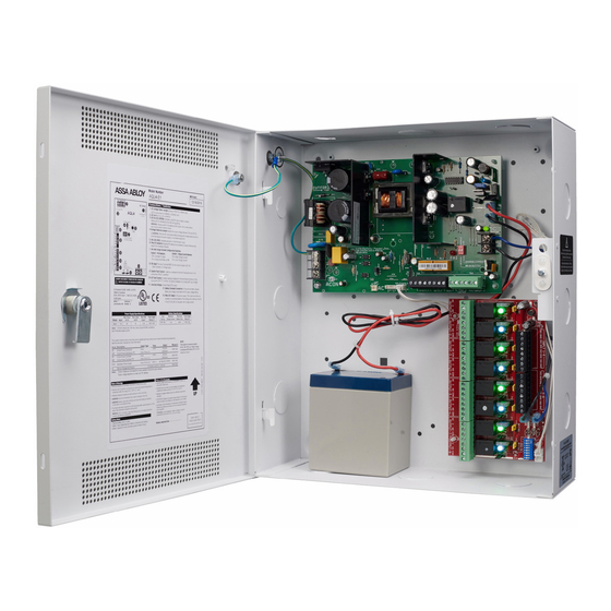
Securitron
Intelligent Power System
Quick Start Guide
Overview
This guide gives the basic information needed to install a system
containing a single Securitron AQL Power supply for most applications.
1
AC Input Voltage Selection – Leave INTACT
for 120 V input. CUT for 230 V input.
Failure to cut this jumper when using the Securitron AQL
with a 230VAC input will result in damage to the system.
2
AC Input – The primary AC connection. Cut JP1 for 230 VAC input.
3
AC ON LED (GREEN) – Indicates a valid AC input voltage is
present. Missing AC is indicated by this LED extinguishing.
Always confirm the absence of AC power with a meter
before servicing to prevent electric shock.
4
FAI LED (RED) – Indicates activation of the Fire Alarm Input.
5
Charge Current / Main output FAI Configuration Switches
SWITCH 1
FAI Selection
OFF = Constant Output
ON = Output switches on FAI
6
FLEX IO Connector – Supplies FAI status to any accessory
boards. Receives fault signal from accessory boards.
7
System Fault Contact – Contact labeling is adjacent to the
terminals and shown in the unpowered (FAULT) condition.
8
AC Fault Contact – Contact labeling is adjacent to the
terminals and shown in the unpowered (FAULT) condition.
AC fault is indicated on a missing AC Input voltage.
AC Select
1
2
N
L
AQL6
®
SWITCH 2
Charge Current
OFF = High Charge Current
ON = Low Charge Current
For UL compliance, the AC fault contact must
be monitored by a listed control panel
13
14
3
9
AUX Voltage – The auxiliary voltage is a fixed
Class 2 Power Limited DC output.
10
FAI Input – The input from the FACP. Can be wired to
accept a NO, NC, Open Collector, or Voltage input.
11
Main Output – This is the main DC output of the power
supply. The output can either be constant or switched based
on the configuration setting of switch 1 (see number 5 on this
page). The DC ON LED will light: GREEN 12 V | BLUE 24 V.
12
Battery Terminal Connection – The connection
for the optional backup battery. Battery set voltage
must match the DC output voltage setting.
13
12/24 V Selection Jumper – This selects the output voltage
between 12 V and 24 V DC. The Securitron AQL Power supply must
be completely powered down before changing this setting. Voltage
markings are printed on the PC Board adjacent to the selector.
Remove AC input power before changing the voltage select switch
to avoid damaging the power supply or connected equipment.
14
DataLink Connection – This connector allows optional
programming and monitoring of the Securitron AQL power
supply via an optional NetLink network module. See the
instructions for the Netlink module for more information.
4
7
8
9
6
SYS FLT AC FLT
SYS FLT
AC FLT
AUX
AUX
Specifications and more details
found in the full manual here.
(Downloadable pdf)
+
12
–
5
ON
11
1 2
1 2
10
FAI INPUT
FAI INPUT
Observe
battery polarity
or damage
may result
Advertisement
Table of Contents

Subscribe to Our Youtube Channel
Related Manuals for Assa Abloy Securitron AQL6


Summary of Contents for Assa Abloy Securitron AQL6
- Page 1 Securitron AQL6 ® Intelligent Power System Quick Start Guide Overview Specifications and more details found in the full manual here. This guide gives the basic information needed to install a system (Downloadable pdf) containing a single Securitron AQL Power supply for most applications. AC Input Voltage Selection –...
- Page 2 1" long screws to the edge of the enclosure’s cover for additional security. Patent pending and/or patent www.assaabloydss.com/patents Copyright © 2020, Hanchett Entry Systems, Inc., an ASSA ABLOY Group company. techsupport.esh@assaabloy.com | assaabloyesh.com All rights reserved. Reproduction in whole or in part without the express written 800 626 7590 | 10027 S.
Need help?
Do you have a question about the Securitron AQL6 and is the answer not in the manual?
Questions and answers