Table of Contents
Advertisement
Quick Links
- 1 Main Assembly - Front View - A-5846-10 Sh't. 1 of 5 Rev. a
- 2 Main Assembly - Lower Right View - A-5846-10 Sh't. 3 of 5 Rev. a
- 3 Main Assembly - Hydraulic Power Unit - 16541-3 Rev. a
- 4 Hydraulic Power Unit Assembly - H-356-4 Rev. B
- 5 Hydraulic Power Unit - H-372-5
- 6 Spindle Block Assembly A-5847-1-6R Rev. B
- Download this manual
The Challenge Machinery Company provides owner's manuals on its
products solely as a courtesy to its customers. See the information below
before using this manual.
These manuals are for reference only. These manuals include products which are noncurrent,
unsupported or no longer produced by The Challenge Machinery Company, and are provided solely as
an accommodation to our customers. By providing these manuals, The Challenge Machinery Company
makes no representation or warranty as to the products, their current condition, or their suitability or fitness
for use in any particular application, which are the sole and independent responsibility of the product
owner and user.
Older products may not comply with current safety procedures, guidelines or regulations, and it
is the product owner's and user's responsibility to evaluate the suitability and fitness of the
products in their current use and application. The Challenge Machinery Company makes no
representation, warranty or recommendation regarding any modifications which may be required
on non-current or unsupported products. The Challenge Machinery Company assumes no liability
for any modification or alteration to any Challenge product, and any such modification or
alteration to any Challenge product is not authorized by The Challenge Machinery Company. The
availability of these manuals is solely for the purpose of providing reference information for the products.
This manual may not be complete in all aspects of product maintenance and repair. All products should
be used only by qualified and properly trained personnel, following proper safety procedures. All
products should be regularly inspected and maintained, and their condition, application and use should
be periodically evaluated by qualified personnel. Only qualified and properly trained technicians should
perform maintenance, repair and replacement procedures. Attempting these procedures without proper
training may cause machine damage or operator injury!
Products may be unsupported by The Challenge Machinery Company due to age or the unavailability of
parts from their original manufacturer. No parts or product support will be available to repair or maintain
unsupported products. Older products may not be UL listed (if the product does not have a UL label it is
not a listed product), and may not comply with applicable installation or other regulations or requirements
if relocated to a new facility. Many municipalities require a product to be UL listed before an electrician
will connect power to them. Often the cost of updating an older product to comply with current safety
regulations is greater than the value of the product.
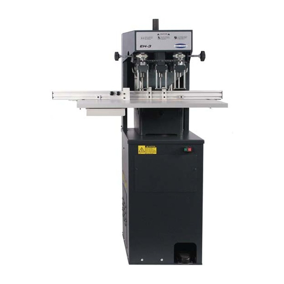
MODEL EH-3D
Technical Service and Parts Manual
Serial Numbers:
085279 through 159999,
EH3-D-150000 and up
Sold and Serviced by
The Challenge Machinery Company
6125 Norton Center Drive
Norton Shores, MI 49441-6081 USA
F.352-LT
ChallengeMachinery.com
November 2018
Advertisement
Table of Contents

Related Manuals for Challenge EH-3D


Summary of Contents for Challenge EH-3D
- Page 1 Products may be unsupported by The Challenge Machinery Company due to age or the unavailability of parts from their original manufacturer. No parts or product support will be available to repair or maintain unsupported products.
-
Page 2: Introduction
DIRECTLY TO CHALLENGE. If you bought a used machine, it is important to have the following information on record at Challenge. Copy this page, fill in the information and send it care of The Challenge Service Department, 6125 Norton Center Dr. -
Page 3: Table Of Contents
5.8 Removing the Cutting Blocks ....................15 5.9 Removing the Drills from the Spindle ..................15 6.0 Drilling Tips ............................ 16 7.0 Accessories for Challenge Paper Drilling Machine ................ 17 7.1 Genuine Challenge Hollow Drills ....................17 7.2 Challenge Drill-Ease Lubricant Stick ..................18 7.3 Challenge Drilling Blocks ...................... - Page 4 1.0 Introduction 8.5 Hydraulic ............................ 28 8.5.1 Recommended Oils ......................28 9.0 Parts Lists & Schematics ........................ 30 9.1 Main Assembly – Front View – A-5846-10 Sh’t. 1 of 5 Rev. A ..........30 9.2 Main Assembly – Front View – A-5846-10 Sh’t. 1 of 5 Rev. D ..........32 9.3 Main Assembly –...
-
Page 5: Safety
If the machine sounds or operates abnormally, turn it off and consult the Trouble Shooting section of this manual. If the problem cannot be corrected, have it checked by a qualified service person or your Authorized Challenge Dealer. Have your electrician make sure the machine is properly grounded and that there is sufficient power to operate the machine properly. -
Page 6: Warning Label Definitions
2.0 Safety 2.3 Warning Label Definitions The following warning labels are found at various locations on your machine. Read and understand the meaning of each symbol. If a label is lost from the machine, it should be replaced HAZARDOUS AREA Disconnect power before cleaning, servicing, or making adjustments not requiring power. -
Page 7: Specifications
Net Weight (@) 525lbs 236kg Shipping Weight (@) 570lbs 257kg Electrical 208/230 Volts (+/-10%)/18Amps, 1 phase, 50/60Hz, AC. Service size: 30Amps. Challenge reserves the right to make changes to any product or specification without notice and without incurring responsibility to existing units. -
Page 8: Installation Guide
4.0 Installation Guide 4.0 Installation Guide Refer to Figure 1on this page as well as the parts lists and drawings in the back of this manual for part identification and orientation, if necessary. All guards and instruction plates are installed for your safety and information and must remain on the machine as shipped from the factory. -
Page 9: Uncrating The Paper Drill
4.0 Installation Guide 4.1 Uncrating the Paper Drill This machine is shipped on a wooden skid and is enclosed with a protective corrugated cover. It is held onto the skid with plastic straps. Remove the straps and carefully cut the corrugated cover down the side and unwrap it from around the machine. -
Page 10: Using Auto-Trip Backgauge
4.0 Installation Guide Figure 3 Pull Down Shaft Figure 4 4.2.2 Using Auto-Trip Backgauge: Attach the backgauge assembly to the table and set both sides to the 6” position (as shown in Figure 5). Next, position the table so that the front surface of the backgauge is 1-7/8” from the front of each pull down shaft (see Figure 5). -
Page 11: Installing The Drill Blocks And Drills
Lock Out Procedures, page 5. This EH-3D is factory wired for 230 Volts, single phase, 50/60Hz and is supplied with a power cord with a NEMA ‘L6-30P’ plug. It is the customer’s responsibility to have a NEMA ‘L6-30R’ receptacle wired by a licensed electrician to a 30 Amp circuit (minimum). -
Page 12: Installing The Chip Container
4.0 Installation Guide 4.6 Installing the Chip Container The chip container is installed by slipping it over the two hooks provided on the rear of the machine. -
Page 13: Operation
5.0 Operation 5.0 Operation 5.1 Starting the Machine The power for this machine is supplied by two motors; one is for the hydraulic power pack, the other is for the spindle. They are both started and stopped simultaneously by a single set of start-stop buttons located on the stand under the table (Figure 1 on page 8). -
Page 14: Setting The Backgauge Position
5.0 Operation outside of each head. This moves the heads along a shaft. A scale and pointer located at the front of the heads gives a reading in inches and millimeters of the center-line relationship to the center head. When a setting is made, make certain that the clamp knob is tightened again. Any combination of three heads can be used, that is one, two, or three holes may be drilled if desired. -
Page 15: Removing The Cutting Blocks
5.0 Operation Figure 8 5.8 Removing the Cutting Blocks Each cutting block is removed by inserting your fingers in the hole provided in the frame (under the table) and pushing up on the cutting stick knock out. There are three holes: one on each side of the frame and one in the front. -
Page 16: Drilling Tips
6.0 Drilling Tips 6.0 Drilling Tips Important! To prevent the drill from overheating, always avoid drilling too slowly. The drill stroke speed should be set at the fastest speed possible that still allows the drills to cut easily through the paper. -
Page 17: Accessories For Challenge Paper Drilling Machine
7.0 Accessories for Challenge Paper Drilling Machine 7.1 Genuine Challenge Hollow Drills In 13 Standard Sizes For Every Drilling Need All drills carried in stock by local Challenge dealers (17/32” & 9/16” available by special order). Hollow Drills Diameter x Drill Capacity Cat. No. -
Page 18: Challenge Drill-Ease Lubricant Stick
CARE MUST ALWAYS BE TAKEN WHEN USING STICK AND HANDLING DRILLS. 7.3 Challenge Drilling Blocks Cat. No. KK-473-3 These Challenge 3” End-Wood Drilling Blocks are for round hole drilling operations. Sold in packages of 12. 7.4 Handi-Sharp Drill Sharpner Cat. No. 57100 Replacement Cutting Bit Part No. -
Page 19: Right Side Guide Kit
2. USE CLOCKWISE ROTATION while maintaining an even pressure, until the hollow drill is sharpened (usually two or three turns). The cutting tool seldom requires replacing, but when it does become necessary, the bit can be ordered through your Challenge Dealer (Cat. No. 4952). -
Page 20: Setting The Side Guide Stops
The automatic trip gage comes equipped with seven stops. Additional stops can be purchased at a very nominal price. Challenge fixed index gages are recommended where the same job is to be handled over and over again. They are easily and quickly attached and removed. NOTE: When drilling narrow strips, the side guide roller assembly should be mounted on the inside of the side guide assembly. -
Page 21: Two-Hand Control Kit
7.9 Two-Hand Control Kit Cat. No. A-4851-52 This 2-hand control safety kit can be installed on the EH-3D in place of the standard foot pedal control. All of the necessary hardware and instructions are included in the kit. The 2-hand control offers anti-tie-down and anti-repeat features, which means both buttons must be released between each cycle, and both buttons must be pressed within .5 seconds of each other. -
Page 22: Drill Shield Kit
This drill shield safety kit includes a clear Lexan shield that protects the operator from contacting the spinning drills. The kit can be installed on all EH-3A, EH-3B,EH-3C and EH-3D machines. All of the necessary hardware and instructions are included in the kit. -
Page 23: Maintenance Guide
Challenge. The Challenge Machinery Company assumes no liability for any modification or alteration to any Challenge products, and any such modification or alteration to any Challenge product is not authorized by The Challenge Machinery Company. Any... -
Page 24: Troubleshooting
8.0 Maintenance Guide 8.1 Troubleshooting DISCONNECT THE POWER AND LOCK IT OUT whenever working on the machine unless the instructions specifically require the machine to be powered (see Power Lockout Procedure, page 5). Some of the following tests may require the machine to be operational for checking and adjusting. -
Page 25: Routine Maintenance
8.0 Maintenance Guide 8.2 Routine Maintenance Always disconnect the power when cleaning, servicing, or lubricating your drill, see Lock Out Procedures, page 5. Production losses can be reduced if good maintenance practices are followed. The following suggestions may be helpful: 1. -
Page 26: Yearly
8.0 Maintenance Guide 2. Use only one of the recommended oils or an ISO VG 100 Hydraulic Fluid equivalent. Oils other than the recommended type will cause seals, cups and O-rings to deteriorate. See Section 8.5.1 on page 28. 8.2.4 Yearly 1. -
Page 27: Drill Head Replacement
8.0 Maintenance Guide 8.4 Drill Head Replacement Figure 19 Always disconnect the power when cleaning, servicing, or lubricating your drill, see Lock Out Procedures, page 5. Through normal use, bearings will wear and need replacing. Signs of wear are excessive noise, heat, or loose spindles. -
Page 28: Center Head Bearing Replacement
Through normal use, hydraulic systems gum up and seals wear. Signs of wear are hydraulic leaks and erratic operation of the vertical speed. Check with your Authorized Challenge Dealer for a current repair and/or replacement policy. Replace oil yearly. (Capacity: 1-1/2 Quarts/1.4 liters) NEVER USE Automatic Transmission oil or brake fluid as a substitute! Oils other than the recommended type will cause seals, cups and O-rings to deteriorate. - Page 29 8.0 Maintenance Guide NOTES...
-
Page 30: Parts Lists & Schematics
9.0 Parts Lists & Schematics 9.0 Parts Lists & Schematics 9.1 Main Assembly – Front View – A-5846-10 Sh’t. 1 of 5 Rev. A S/N 085279 to 105487... - Page 31 9.0 Parts Lists & Schematics Main Assembly – Front View, Parts list A - 5 8 4 7 - 1 - 6 R A - 5 8 6 2 - 1 - 6 R...
-
Page 32: Main Assembly - Front View - A-5846-10 Sh't. 1 Of 5 Rev. D
9.0 Parts Lists & Schematics 9.2 Main Assembly – Front View – A-5846-10 Sh’t. 1 of 5 Rev. D S/N 105488 and Up... - Page 33 9.0 Parts Lists & Schematics Main Assembly – Front View, Parts list rev. “D” PART NO. DESCRIPTION OF ACCESSORIES 5700 BACKGAUGE ASM. E-3073-( ) SWITCH - START AND STOP REF. 5712 LABEL - SHOCK HAZARD, COVER REM., ON/OFF S-1864-2 CAPTIVE RETAINING DEVICE K-480-3 FRONT GRILL K-250-8...
-
Page 34: Main Assembly - Upper Right View - A-5846-10 Sh't. 2 Of 5 Rev. A
9.0 Parts Lists & Schematics 9.3 Main Assembly – Upper Right View – A-5846-10 Sh’t. 2 of 5 Rev. A REV “C”... - Page 35 9.0 Parts Lists & Schematics Main Assembly – Upper Right View, Parts List REV. “C” PART NO. DESCRIPTION OF ACCESSORIES 5739 WASTE BIN 41130 SERIAL PLATE 5886 HINGE 5870 HOOK - CHIP BAG E-1172-4 SNAP IN BUSHING E-968-4 CLAMP - 3/8" CABLE S-1880 LABEL - OIL K-2-24...
-
Page 36: Main Assembly - Lower Right View - A-5846-10 Sh't. 3 Of 5 Rev. A
9.0 Parts Lists & Schematics 9.4 Main Assembly – Lower Right View – A-5846-10 Sh’t. 3 of 5 Rev. A... -
Page 37: Main Assembly - Top View - A-5846-10 Sh't. 4 Of 5 Rev. A
9.0 Parts Lists & Schematics 9.5 Main Assembly – Top View – A-5846-10 Sh’t. 4 of 5 Rev. A S/N’s 085279 to 135900... -
Page 38: Main Assembly - Top View - A-5846-10 Sh't. 4 Of 5 Rev. B
9.0 Parts Lists & Schematics 9.6 Main Assembly – Top View – A-5846-10 Sh’t. 4 of 5 Rev. B S/N’s 135901 to 14xxxx PART NO. DESCRIPTION OF ACCESSORIES 5861-1 ARM - IDLER PULLEY 5889 STUD - IDLER PULLEY A-5887-1 PULLEY ASM. - IDLER S-1661-1 BELT - FLAT S-694-4... -
Page 39: Main Assembly - Top View - A-5846-10 Sh't. 4 Of 5 Rev. C
9.0 Parts Lists & Schematics 9.7 Main Assembly – Top View – A-5846-10 Sh’t. 4 of 5 Rev. C S/N’s 14xxxx and Up (ECN 13N070) PART NO. DESCRIPTION OF ACCESSORIES 5861-1 ARM - IDLER PULLEY 5889 STUD - IDLER PULLEY A-5887-1 PULLEY ASM. -
Page 40: Main Assembly - Wiring Detail - A-5846-10 Sh't. 5 Of 5 Rev. A
9.0 Parts Lists & Schematics 9.8 Main Assembly – Wiring Detail – A-5846-10 Sh’t. 5 of 5 Rev. A S/N 085279 to 105487... -
Page 41: Main Assembly - Wiring Detail - A-5846-10 Sh't. 5 Of 5 Rev. B
9.0 Parts Lists & Schematics 9.9 Main Assembly – Wiring Detail – A-5846-10 Sh’t. 5 of 5 Rev. B S/N 105488 and Up... -
Page 42: Power Panel Assembly - Wiring Detail - Ee-3256 Rev. C
9.0 Parts Lists & Schematics 9.10 Power Panel Assembly – Wiring Detail – EE-3256 Rev. C S/N 105487 and Below... - Page 43 9.0 Parts Lists & Schematics Power Panel Assembly – Parts List – EE-3256 Rev. C PART NO. DESCRIPTION OF ACCESSORIES E-3257 PANEL - ELECTRICAL E-2232-1 RELAY E-2742-13 TRANSFORMER, 50VA - 230V PRIM./24V SEC. E-1977-23 MOUNTING RAIL - TERMINAL BLOCK 5" LONG E-3264-7 CIRCUIT BREAKER - TRIP 6A (CB1) E-3264-5...
-
Page 44: Power Panel Assembly - Wiring Detail - Ee-3256-1 Rev. B
9.0 Parts Lists & Schematics 9.11 Power Panel Assembly – Wiring Detail – EE-3256-1 Rev. B S/N 105488 and Up... - Page 45 9.0 Parts Lists & Schematics Power Panel Assembly – Parts List – EE-3256-1 Rev. B PART NO. DESCRIPTION OF ACCESSORIES E-3257 PANEL - ELECTRICAL E-2232-1 RELAY E-2742-13 TRANSFORMER, 50VA - 230V PRIM./24V SEC. E-1977-18 MOUNTING RAIL - TERMINAL BLOCK 6-1/2" LONG E-3264-7 CIRCUIT BREAKER - TRIP 6A (CB1) E-3264-5...
-
Page 46: Main Assembly - Hydraulic Power Unit - 16541-3 Rev. A
9.0 Parts Lists & Schematics 9.12 Main Assembly – Hydraulic Power Unit – 16541-3 Rev. A... - Page 47 9.0 Parts Lists & Schematics Hydraulic Power Unit Assembly – Parts List/Hydraulic Schematic...
-
Page 48: Hydraulic Power Unit Assembly - H-356-4 Rev. B
9.0 Parts Lists & Schematics 9.13 Hydraulic Power Unit Assembly – H-356-4 Rev. B... -
Page 49: Hydraulic Power Unit - H-372-5
9.0 Parts Lists & Schematics 9.14 Hydraulic Power Unit – H-372-5... -
Page 50: Spindle Block Assembly A-5847-1-6R Rev. B
9.0 Parts Lists & Schematics 9.15 R.H. Spindle Block Assembly A-5847-1-6R Rev. B... -
Page 51: Spindle Block Assembly A-5862-1-6R Rev. B
9.0 Parts Lists & Schematics 9.16 L.H. Spindle Block Assembly A-5862-1-6R Rev. B... - Page 52 F.352-LT November 2018...
Need help?
Do you have a question about the EH-3D and is the answer not in the manual?
Questions and answers