Table of Contents
Advertisement
Quick Links
NOTICE: Varian, Inc. was acquired by Agilent
Technologies in May 2010. This document is provided
as a courtesy but is no longer kept current and thus
will contain historical references to Varian. For more
information, go to www.agilent.com/chem.
©Varian, Inc. 2000 - 2004
Varian, Inc.
2700 Mitchell Drive
Walnut Creek, CA 94598-1675/usa
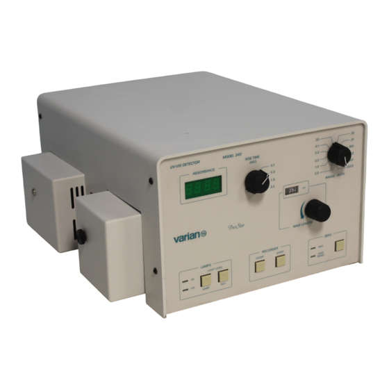
ProStar 340
UV-Vis Detector
Operation Manual
03-914783-00:Rev. 3
Advertisement
Table of Contents
Troubleshooting

Related Manuals for Varian ProStar 340


Summary of Contents for Varian ProStar 340
- Page 1 NOTICE: Varian, Inc. was acquired by Agilent Technologies in May 2010. This document is provided as a courtesy but is no longer kept current and thus will contain historical references to Varian. For more Varian, Inc. information, go to www.agilent.com/chem.
- Page 3 9000 series registration constitutes an objective third-party report to determine the level of a supplier's commitment to quality. In 1992, Varian, Inc., Analytical Instruments became registered to the most comprehensive of the ISO 9000 series standards — ISO 9001. ISO 9001 registration means that every stage of our quality system, including product development, manufacturing, final test, shipping, and parts and supplies has been rigorously examined against the most exacting set of internationally recognized standards.
- Page 4 Customer to return the defective workmanship for the periods specified and in accessory or instrument to Varian or to send it to a accordance with the terms on the face of Varian's designated service facility. The Customer shall be...
- Page 5 NOTES CAUTIONS WARNINGS accordance with this instruction manual and any additional information which may be provided by Varian. Address any questions regarding the safe and proper use of your equipment to your local Varian office. NOTE Information to aid you in obtaining...
- Page 6 It is the responsibility of the Customer to inform Varian Customer Support Representatives if the instrument has been used for the analysis of hazardous biological, radioactive, or toxic samples, prior to any instrument service being performed or when an instrument is being returned to the Service Center for repair.
- Page 7 GC Safety Practices Flash Chromatography The operator should be familiar with the physico- Exhaust System chemical properties of the components of the mobile No special exhaust ducting is necessary for GC phase. detectors installed in a well-ventilated room except Keep solvents from direct...
- Page 8 Varian, Inc. Analytical Instruments Sales Offices For Sales or Service assistance and to order Parts and Supplies, contact your local Varian office. Argentina France...
- Page 9 HINWEIS ACHTUNG WARNUNG, Sie Ihr Gerät in Übereinstimmung mit dieser Arbeitsanleitung und allen möglichen zusätzlichen Informationen von Varian betreiben. Alle Fragen bezüglich Sicherheit und Handhabung Ihres Gerätes richten Sie an Ihr Varian Büro. ACHTUNG WARNUNG HINWEIS Eine Information, um einen optimalen Weist auf Situationen, die zu mäßiger...
- Page 10 Es muß mit geeigneten Gasen und/oder Lösungsmitteln und innerhalb der im Handbuch spezifizierten maximalen Werte für Druck, Flüsse und Temperaturen betrieben werden. Der Kunde ist vor der Durchführung irgendeines Geräteservices verpflichtet den Varian WARNUNG Kundendienstvertreter zu informieren, wenn das Instrument für Analysen gefährlicher biologischer, radioaktiver oder toxischer Proben benutzt worden ist.
- Page 11 Öffnen Sie niemals eine unter Druck stehende GC Sicherheitspraktiken Lösungsmittelleitung oder ein Ventil. Halten Sie Abgassystem zuerst die Pumpe an und lassen Sie den Druck auf Für GC Detektoren, die in einem gut durchlüfteten Null abfallen. Raum installiert sind, ist keine spezielle Abgasführung Benutzen Sie splittersichere Reservoirs, die für erforderlich, außer wenn die Detektoren zum Testen einen Druck von 3,4 bis 4,1 bar ausgelegt sind.
- Page 12 Verfügbarkeit von Ersatzteilen Serviceverfügbarkeit Varian bietet seinen Kunden auch Es ist Varian’s Grundsatz, Ersatzteile für alle Instrumente und die wichtig- nach dem Auslaufen der Garantie sten Zubehöre für einen Zeitraum von fünf (5) Jahren nach dem Fertigung- eine Vielfalt von Serviceleistungen sauslauf dieser Geräteserie verfügbar zu haben.
- Page 13 AVERTISSEMENTS. matériel conformément aux instructions du présent manuel et à toute autre information émanant de Varian. S’adresser au bureau régional Varian pour toute question relative à la sécurité ou à l’utilisation correcte du matériel. NOTE Information destinée à tirer le Attire l’attention sur une situation...
- Page 14 Le client est tenu d’informer le service Varian d’assistance à la clientèle que son matériel ATTENTION a été utilisé pour l’analyse d’échantillons biologiques dangereux, radioactifs ou toxiques avant que n’en soit effectué...
- Page 15 Ne jamais déconnecter un conduit de solvant ou Mesures de sécurité en CPG une vanne sous pression. Arrêter préalablement la Système d’échappement pompe et laisser la pression descendre à zéro. Les détecteurs CPG installés dans une pièce bien Utiliser des réservoirs incassables à 50-60 psi. ventilée ne nécessitent pas de conduits spéciaux d’échappement excepté...
- Page 16 Points de vente des instruments analytiques Varian Contactez votre point de vente régional Varian pour toute question commerciale ou de service d’assistance à la clientèle ou pour passer commande de pièces et de fournitures.
- Page 17 . E’ importante che lo strumento venga utilizzato rispettando le istruzioni fornite in questo CAUTELA ATTENZIONE manuale o che verranno fornite successivamente dalla Varian. Per ogni eventuale chiarimento sull’uso o sulla sicurezza, si prega di contattare la Varian di Leinì (TO). ATTENZIONE...
- Page 18 E’ responsabilità del Cliente informare il Servizio Tecnico Varian, prima di qualsiasi ATTENZIONE intervento di riparazione, se lo strumento è stato utilizzato per l’analisi di campioni biologicamente pericolosi, radioattivi o tossici.
- Page 19 Non smontare mai una linea del solvente od una Procedure di Sicurezza in GC valvola quando il sistema è sotto pressione. Scarico dei Gas Fermare prima la pompa ed aspettare che la Per i rivelatori GC non è richiesto alcun sistema pressione scenda a zero.
- Page 20 Disponibilità delle Parti di Ricambio Servizi Tecnico E’ politica della Varian il fornire le parti di ricambio per lo strumento ed La Varian, alla scadenza del periodo i suoi accessori per un periodo di cinque (5) anni a partire dalla data di di garanzia, è...
- Page 21 PRECAUCION ATENCION el instrumento de acuerdo con este Manual de Operación y cualquier otra información que le proporcione Varian. Remita a la Oficina Local de Varian cualquier cuestión que tenga respecto al correcto uso de su equipo. ¡PRECAUCION! ATENCI N Ó...
- Page 22 Debe ser operado usando gases y/ó disolventes apropiados y con unos niveles máximos de presión, flujos y temperaturas, según se describe en este manual. El Usuario tiene la obligación de informar al Servicio Técnico de Varian cuando el ATENCI N Ó...
- Page 23 Nunca abra una línea ó una válvula bajo presión. GC Prácticas de Seguridad Apague la bomba antes y deje que la presión baje a Sistema de Extracción cero. No se necesita un sistema de extracción para los Utilice depósitos irrompibles que sean capaces de detectores GC instalados en un laboratorio bien operar a 50-60 psi.
- Page 24 Disponibilidad de Recambios Disponibilidad de Servicio Es Política de Varian disponer de Recambios para cualquier instrumento y la mayoría de los accesorios por un periodo de cinco (5) años después del Varian ofrece una gran variedad de último instrumento fabricado. Los recambios durante esos cinco años sistemas de Servicio para mantener estarán disponibles, pero siempre bajo el sistema “Según disponibilidad”.
-
Page 25: Table Of Contents
Shut Down......................20 Maintenance and Troubleshooting ............21 Changing the Flowcells ....................21 Flow Cell Maintenance....................24 Cleaning the Flowcells ..................24 Cell Disassembly ....................24 Flow Cell Reassembly ..................25 Changing the Lamp.....................28 Deuterium (D2) Lamp ....................28 Removing the D2 Lamp ..................29 ProStar 340 UV-Vis Detector... - Page 26 Installing the D2 Lamp ..................30 Tungsten Lamp ......................30 Removing the Tungsten Lamp................31 Installing the Tungsten Lamp................31 Troubleshooting ......................32 Light Intensity Diagnostics .................32 Proper Full Scale Voltage Output ..............33 Filter Bypass Switch...................33 Troubleshooting Guide..................34 Appendix ....................37 Specifications ......................37 Parts and Accessories ....................38 03-914783-00:3...
-
Page 27: Introduction
Introduction The ProStar 340 is a variable wavelength UV/visible absorbance detector for liquid chromatography. Using various combinations of flowcells and lamps, the detector can be adapted for applications from capillary to preparative scale. Theory of Operation Figure 1 illustrates the optical system for the detector. Only one lamp (D2 or tungsten) can be mounted at a time. - Page 28 True double beam operation is provided by a fiberoptic beam splitter. A reference photodiode continuously monitors the light from one leg of the beam splitter. The other leg is imaged by a lens through a sample cell onto the sample photodiode. The photodiodes are connected to individual preamplifiers.
-
Page 29: Installation
If any items are missing, contact LC Technical Services at 1-800-FOR-HPLC, or your local Varian office. In addition to the detector, you will need the following items for setup and initial operation: •... -
Page 30: Location
Location Place the detector on a firm, flat surface, such as a laboratory bench top, near the column outlet. Allow at least 5 inches of clear space between the rear panel of the unit and any wall or obstruction. This gives access to the rear panel connections and provides a free flow of cooling air. -
Page 31: System Description
3. Range Selection Switch: A twelve-position rotary switch controls the full scale output range for the rear panel- positioned Recorder Output. Full scale ranges of 2.0, 1.0, 0.5, 0.2, 0.1, 0.05, .02, 0.01, 0.005, 0.002, 0.001, and 0.0005 ProStar 340 UV-Vis Detector... - Page 32 AUFS are provided. This switch does not affect the fixed 1V/AU output of the rear panel integrator output. 4. Wavelength Indicator: A mechanical three-digit indicator displays operating wavelength. 5. Wavelength Selector: A mechanical continuous turn control selects wavelengths from 190 to 800 nm. Rotating this control clockwise decreases wavelength;...
- Page 33 EVENT LAMP + – + – + – + – + – 1 2 3 4 5 6 OPEN FILTER BYPASS RECORDER 100mV INT. OFFSET 10mV REC. OFFSET 100V 120V 220V 240V Figure 4 Back Panel ProStar 340 UV/Vis Detector...
- Page 34 1. Earth Ground: This terminal is continuous with the earth ground. NOTE: Do note use this terminal as negative ground for any output or input function. Doing so may create ground loops resulting in excessive noise. 2. Recorder Outputs: Two terminals supply an analog output for a strip chart recorder or integrator.
- Page 35 (for 100-120 Vac operation) and two 0.5 Amp slow-blow fuses (220-240 Vac operation). 17. Voltage Control Selector: A four position voltage selector allows the instrument to be operated at 100, 120, 220, or 240 Vac (50/60 Hz). ProStar 340 UV/Vis Detector...
-
Page 36: Flowcell Housing And Lamp Housing
Flowcell Housing and Lamp Housing BACK PANEL Figure 5 Flowcell Housing and Lamp Housing WARNING: BURN HAZARD NEVER remove the lamp housing cover when power is connected. UV radiation from the D2 lamp can damage skin and eyes. Lamps become very hot. Use care when handling them to avoid burns. -
Page 37: Electrical Connections
The outlet and inlet tubing ID, OD, and position may vary according to the flowcell in use. Consult the flowcell manual for more details. Electrical Connections Figure 6 Voltage Selection ProStar 340 UV/Vis Detector... -
Page 38: Setting Voltage
Setting Voltage WARNING: SHOCK HAZARD Make sure the power cord is disconnected from the rear panel of the detector. Refer to the figure above. Check the voltage selector block located next to the power cord connector on the rear panel. The plastic tab indicates the voltage for which instrument has been set (100, 120, 220, or 240V;... -
Page 39: Recorder Connections
However, its output will reflect the zeroing of the autozero circuit. Thus, a changing baseline can be corrected by pushing the autozero switch. Connect the input line of the integrator in an identical manner as was outlined for the strip chart recorder. ProStar 340 UV/Vis Detector... -
Page 40: Power Cord
Power Cord Power to the detector is provided by a standard modular power cord assembly. Connect the power cord to the receptacle next to the fuse block. Remote Connections The detector provides external remote control connections. (You do not need to connect these in order to finish the initial installation and check-out. -
Page 41: Lamp
Before connecting a new piece of tubing or column to the detector, pump several mL of clean solvent through it to waste. This action will clean any particulates or oil from the inside bore of the tubing, which would otherwise reach the sample cell or heat exchanger. ProStar 340 UV/Vis Detector... - Page 42 03-914783-00:3...
-
Page 43: Operation
After the lamp has ignited and the autozero button has been pushed, it will be necessary to push the Short Switch to set the ProStar 340 UV-Vis Detector... -
Page 44: Setting Detector Controls
recorder output to zero volts to allow adjustment of the chart recorder pen. The Short Switch does not affect the integrator output. Set the detector to a more sensitive range such as 0.01 AUFS and monitor the baseline until a straight, non-drifting baseline is noted. -
Page 45: Range
Zero the detector, inject your sample, and activate the event mark. You should note an approximate 20% deflection on the recorder. Note the peaks as they appear on the strip chart recorder. Readjust the parameters of wavelength, range, and rise time to optimize the chromatography. ProStar 340 UV/Vis Detector... -
Page 46: Shut Down
Shut Down As a general rule, it is recommended that the flowcell be flushed with several volumes of clean, non-ionic eluant. This is especially important if ionic buffer solutions have been used. After flushing, simply turn the power switch on the back panel to the OFF (downwards) position. -
Page 47: Maintenance And Troubleshooting
This section of the manual provides general guidelines for maintenance and service of the flowcell and lamp assemblies. The flowcell is located in the forward housing on the left side of the detector. ProStar 340 UV-Vis Detector... - Page 48 Cell Cover Photodiode Retaining Screw Photodiode Mount Tubing Strain Relief Thrumbscrew Cell Retaining Screws Tubing Strain Relief Clamp Cell Body Assembly Cell Holder Cell holder Tumbscrews 10. Lamp Light Shield Screw 11. Lamp Light Shield 12. Deuterium Lamp Assembly and Plug 13.
- Page 49 11. Reconnect the inlet line to the column or connecting tubing and reconnect the outlet tubing to the fraction collector, back-pressure device, or appropriate waste reservoir. 12. Reconnect the power cord to the rear panel of the detector. ProStar 340 UV/Vis Detector...
-
Page 50: Flow Cell Maintenance
Flow Cell Maintenance Cleaning the Flowcells If at all possible, we discourage the disassembly of flowcells for routine cleaning purposes. Most cells can be adequately cleaned by flushing with several milliliters of appropriate solvent. We recommend the following solvents for this purpose: 1. -
Page 51: Flow Cell Reassembly
(large hole) and fluid bore (small hole) are exposed by the tear drop. 2. Carefully replace the cell window (9). 3. Install the retaining washer (10) so that its concave surface faces away from the cell body. ProStar 340 UV/Vis Detector... - Page 52 4. Replace the window retaining nut (11). Tighten to 14 inch- pounds. To avoid possible damage to the windows, do not exceed 14 inch-pounds of torque. 5. Repeat steps 1 through 4 for the other side of the flow cell. 6.
- Page 53 AINTENANCE AND ROUBLESHOOTING Figure 10 Flowcell ProStar 340 UV/Vis Detector...
-
Page 54: Changing The Lamp
Changing the Lamp The detector accepts two light sources: a deuterium lamp (for wavelengths in the range 190-380 nm) and a tungsten lamp (for wavelengths in the range 380-800 nm). If your detector was ordered for operation in the visible spectrum, the tungsten lamp is installed. -
Page 55: Removing The D2 Lamp
UV light can damage eyes and skin. Always disconnect the power cord before working in the vicinity of the lamp. WARNING: BURN HAZARD The D2 lamp gets very hot. Care must be taken while handling it to prevent burns. Always allow the lamp to cool before removal. ProStar 340 UV/Vis Detector... -
Page 56: Installing The D2 Lamp
3. Disconnect the UV lamp lead from the detector by gently pulling it straight back toward you. DO NOT twist the connector while pulling (see Figure 11). 4. Unscrew the two thumbscrews holding the lamp mount in place, and pull the lamp mount straight back towards you. Be careful not to lose the two aluminum standoffs or the thumbscrews. -
Page 57: Removing The Tungsten Lamp
2. Remove the screw and remove the lamp housing on the left side of the detector to expose the tungsten lamp. Installing the Tungsten Lamp 1. Slide the tungsten lamp assembly along the same alignment dowel used for the D2 lamp (see Figure 11B). ProStar 340 UV/Vis Detector... -
Page 58: Troubleshooting
2. Fasten the tungsten lamp assembly using the same two screws and aluminum standoffs that are used to fasten the D2 lamp assembly to the detector. 3. Plug the tungsten lamp power cord into the lower of the two receptacles located on the detector. 4. -
Page 59: Proper Full Scale Voltage Output
0.1 seconds is created. To deactivate the Filter Bypass Circuit: 1. Push the bottom half of Switch #6 (see Figure 7) until it rocks downward to the OFF position. ProStar 340 UV/Vis Detector... -
Page 60: Troubleshooting Guide
Troubleshooting Guide For further assistance phone 1-800-FOR-HPLC or contact your local Varian office. Symptom Possible Cause Suggested Remedy Spikes on a Bubbles passing through Degas solvent and/or supply back recorder baseline. cell. pressure to the sample cell, also check all high pressure fittings for leaks (both liquid and gases). - Page 61 Large temperature Remove detector from the source of fluctuations are occurring. drafts of hot and cold air. Flowcell, photodiode Tighten thumbscrews fastening assembly, or flowcell flowcell holder and flowcell cover. cover is loose. ProStar 340 UV/Vis Detector...
- Page 62 03-914783-00:3...
-
Page 63: Appendix
2x time constant in seconds. A filter bypass switch located on the rear panel provides an equivalent rise time of 0.1 seconds. Display: A 3½ digit LED displays absorbance and relative sample and reference light intensities. ProStar 340 UV-Vis Detector... -
Page 64: Parts And Accessories
Flowcells: Pathlengths from 0 mm to 10 mm, cell volumes from 0 mL to 15 mL, stainless steel, titanium, or Kel-F, contact materials, sapphire windows. 1000 psi pressure rating for stainless steel cells, 500 psi pressure rating for Kel-F cells, 2,000 psi pressure rating for variable pathlength preparative cells;...
Need help?
Do you have a question about the ProStar 340 and is the answer not in the manual?
Questions and answers