Table of Contents
Advertisement
Quick Links
Service Manual
FOR
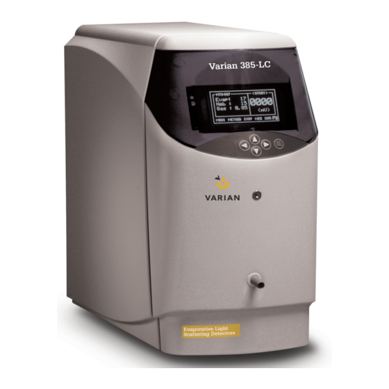
Varian 380-LC & 385-LC
EVAPORATIVE
LIGHT-SCATTERING
DETECTOR
Version 1.0 January 2008
PL0890-0360
Polymer Laboratories Ltd, Now a part of Varian, Inc., Essex Road, Church Stretton,
Shropshire SY6 6AX, UK
Tel +44 (0)1694 723581, Fax +44 (0)1694 722171, Service Tel +44 (0)1694 724333
Polymer Laboratories, Varian, Inc., Amherst Fields Research Park, 160 Old Farm Road,
Amherst, MA 01002, USA Tel +1 413 253 9554, Fax +1 413 253 2476
Polymer Laboratories, Varian B.V., Herculesweg 8, 4339 PL Middelburg,
The Netherlands Tel +31 (0)118 671500, Fax +31 (0)118 671502
Polymer Laboratories, Varian Belgium NV SA, Mechelsesteenweg 362,
2860 St.-Katelijne-Waver, Belgium Tel +32 (0) 15 556460, Fax +32 (0) 15 556186
Polymer Laboratories, Varian Deutschland GmbH, Alsfelder Straße 6,
D-64289 Darmstadt, Germany Tel: +49 (0)6151 7030 Fax: +49 (0)6151 703237
Varian S.A.,7 Avenue des Tropiques, Z.A. Courtaboeuf, B.P. 12
F-91941 Les Ulis Cedex, France Tel +33 1.6986.3838 Fax: +33 1.6928.2308
Advertisement
Table of Contents


Need help?
Do you have a question about the 380-LC and is the answer not in the manual?
Questions and answers