
Related Manuals for Hillrom Welch Allyn H12+


Summary of Contents for Hillrom Welch Allyn H12+
- Page 1 Welch Allyn H12+™ ® 12-lead Holter Service Manual CAUTION: Federal law restricts this device to sale by or on the order of a physician.
- Page 2 For information about any Welch Allyn product, visit: https://www.welchallyn.com/en/about- us/locations.html Customer Service and Technical Support: https://www.welchallyn.com/en/other/contact-us.html 1.888.667.8272, mor_tech.support@hillrom.com 80026044 Ver. A Revision date: 2020-04 901141 HOLTER RECORDER Welch Allyn, Inc. 4341 State Street Road Skaneateles Falls, NY 13153 USA...
-
Page 3: Table Of Contents
TABLE OF CONTENTS SERVICE AND SPARE PARTS ........................... 3 ..............................3 SSISTANCE AND ARTS ..................................3 EPAIRS NOTICES ................................. 5 ’ ............................ 5 ANUFACTURER ESPONSIBILITY ............................ 5 ESPONSIBILITY OF THE USTOMER ............................. 5 QUIPMENT DENTIFICATION ..........................5 OPYRIGHT AND RADEMARK OTICES ............................. - Page 4 TABLE OF CONTENTS ............................... 35 PENING THE ................................ 36 EYPAD EMOVAL LCD R & R ............................. 38 EMOVAL EPLACEMENT & R ........................40 IGITAL OARD EMOVAL EPLACEMENT & R ......................... 40 RONT OARD EMOVAL EPLACEMENT PROGRAMMED DIGITAL PCBA ................ 42 NTERING A SERIAL NUMBER ONTO A NEW PRINTED CIRCUIT BOARDS ...........................
-
Page 5: Service And Spare Parts
SERVICE AND SPARE PARTS Assistance and Parts If the product fails to function properly or if assistance, service or spare parts are required, contact the nearest Welch Allyn Technical Support Center. https://www.welchallyn.com/en/other/contact-us.html When calling, please be prepared to provide: Product name and model number and complete description of the problem ... - Page 6 SERVICE AND SPARE PARTS...
-
Page 7: Notices
NOTICES Manufacturer’s Responsibility Welch Allyn is responsible for the effects on safety and performance only if: • Assembly operations, extensions, readjustments, modifications, or repairs are carried out only by persons authorized by Welch Allyn. • The device is used in accordance with the instructions for use. Responsibility of the Customer The user of this device is responsible for ensuring the implementation of a satisfactory maintenance schedule. - Page 8 NOTICES...
-
Page 9: User Safety Information
USER SAFETY INFORMATION WARNING: Means there is the possibility of personal injury to you or others. Caution: Means there is the possibility of damage to the device. Note: Provides information to further assist in the use of the device. WARNING(S) ... - Page 10 USER SAFETY INFORMATION This device was designed to use the electrodes specified in this manual. Proper clinical procedure must be employed to prep the electrode sites and to monitor the patient for excessive skin irritation, inflammation, or other adverse reactions. ...
-
Page 11: Caution(S)
USER SAFETY INFORMATION Caution(s) The H12+ recorder is not waterproof. It may be placed in an optionally available sealed, clear pouch that will protect it from moisture, but should not be submerged in water. To prevent possible damage to the device, do not use sharp or hard objects to depress buttons, only use fingertips. -
Page 12: Note(S)
USER SAFETY INFORMATION Note(s) Proper patient preparation is important to proper application of ECG electrodes and operation of the device. If electrode is not properly connected to the patient, or one or more of the patient cable lead wires is damaged, display will indicate a lead fault for the lead(s) where the condition is present. -
Page 13: Equipment Symbols
EQUIPMENT SYMBOLS Symbol Delineation For information on the origin of these symbols, see the Welch Allyn symbols glossary: http://www.welchallyn.com/symbolsglossary. Electrostatic sensitive devices WARNING The warning statements in this manual identify conditions or practices that could lead to illness, injury, or death. In addition, when used on a patient applied part, this symbol indicates defibrillation protection is in the cables. - Page 14 EQUIPMENT SYMBOLS...
-
Page 15: General
GENERAL Service Manual Purpose The purpose of this manual is to provide information to service personnel in order to maintain and repair the H12+ Holter Recorder. This manual includes parts lists and is intended to function primarily as a guide to preventative and corrective maintenance and electrical repairs considered field repairable. - Page 16 GENERAL...
- Page 17 GENERAL...
-
Page 18: Maintenance
MAINTENANCE Introduction This section provides servicing and maintenance instructions for the H12+ Holter Recorder. Subsequent parts of this section are disassembly, inspection techniques, and cleaning techniques. Cleaning and Inspecting Techniques This section describes the procedures for cleaning and disinfecting the H12+ and accessories. WARNING: Follow these instructions to clean and disinfect the H12+ and its accessories. -
Page 19: Cleaning And Disinfecting Accessories
MAINTENANCE To clean the H12+: Remove carry case and disconnect ECG cable from the device. Disconnect power source by removing AA. Reinstall the battery door. Thoroughly wipe the surface of the H12+ with a clean, lint-free cloth dampened with a mild detergent and water for general cleaning or use one of the above recommended agents for disinfection. -
Page 20: Periodic Maintenance
MAINTENANCE WARNING: Prevent liquid from penetrating the device and do not attempt to clean/disinfect the device or patient cables by submerging into a liquid, autoclaving, or steam cleaning. Never expose cables to strong ultra-violet radiation. Do not sterilize the device or ECG cable with Ethylene Oxide (EtO) gas. -
Page 21: Battery Terminal Inspection
MAINTENANCE Battery Terminal Inspection 1. Remove the battery door. Remove the battery. 2. Check battery connection terminals for debris and/or corrosion. CAUTION Be sure that the polarity of the battery is correct. Follow diagram in cover. 3. Re-install the battery. -
Page 22: Technical Description
TECHNICAL DESCRIPTION H12+ Overview Feature Specifications Instrument Type 12-lead digital Holter recorder Input Channels Simultaneous acquisition of all leads Standard Leads Acquired I, II, III, aVR, aVL, aVF, V1, V2, V3, V4, V5, and V6 +/- 300 mV with a resolution of 2.5 µV/LSB Input Dynamic Range 0.05 to 60 Hz for standard recording Frequency Response... -
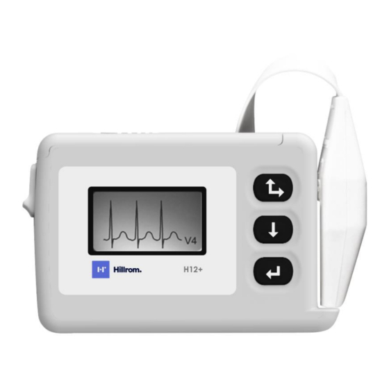
Page 23: H12+ Digital Recorder
TECHNICAL DESCRIPTION H12+ Digital Recorder The SD-card slot and the battery compartment are accessible via the battery door of the H12+ Recorder. Opening and Closing the Battery Door 1. To open the battery door, hold the latch (1) down and then depress and slide the battery door (2) until it stops. - Page 24 TECHNICAL DESCRIPTION Inserting and Removing SD Cards To insert an SD card, open the battery door of the recorder. Position the card above the empty card slot with the label facing front as shown below. Place the SD card in the slot and gently push down on the SD card until it is firmly engaged and can move no further.
- Page 25 TECHNICAL DESCRIPTION Attaching the Patient Cable The patient cable consists of a connector block, main cable and ten lead-wires connected to the main cable. Each lead-wire terminates in a snap connector. The lead-wires are positioned on the main cable to follow the contour of the torso.
- Page 26 TECHNICAL DESCRIPTION Using the Keypad The keypad is located on the front, right-side of the H12+ Recorder. Three keys are available for navigating through the LCD screens and for entering the patient ID and event markers during the recording. These include the Up/Right, Down and Enter keys. During patient hook-up, the Down and Up keys are used to scroll through the Main menu options, to enter the Patient ID and to set the date/time and language.
- Page 27 TECHNICAL DESCRIPTION...
- Page 28 TECHNICAL DESCRIPTION The TARGET RATE / DURATION SETTINGS, LEAD CHECK, DISPLAY ECG, ENTER ID and CONFIGURE tasks are performed prior to starting a new patient recording. With the exception of CONFIGURE, the other three tasks typically are done for each new recording. Note: Patient ID entry (ENTER ID) is optional.
- Page 29 TECHNICAL DESCRIPTION Displaying ECG Leads DISPLAY ECG is used to visually inspect leads I, II, III, V1, V2, V3, V4, V5 and V6 before starting a recording. Check the signal quality and lead amplitude for each lead. From the Main menu, scroll to DISPLAY ECG using the Down or Up key. Press the Enter key to select this option.
- Page 30 TECHNICAL DESCRIPTION To end patient ID entry, position the cursor over End on the bottom line. Press the Enter key to store the patient ID in the patient record. Configuration CONFIGURE is used to set the current date and time, the date format, the recording duration, language defaults, and to display the software version number.
- Page 31 TECHNICAL DESCRIPTION...
- Page 32 TECHNICAL DESCRIPTION Setting Date and Time DATE/TIME is used to set the current date and time and to set an alternative format for the displayed date. 1. From the configuration menu, scroll to DATE/TIME, press Enter. The DATE/TIME menu includes the following options: ...
-
Page 33: Starting A Recording Session
Note: If the battery door is removed during recording, the H12+ recorder stops recording. A new proprietary Hillrom SD card and fresh battery must be inserted to continue recording. Note: In the event of a lead fail condition occurring during recording, the appropriate lead fail indicator(s) is displayed below the Recording message and will replace the displayed patient ID number until resolved. -
Page 34: Entering (Optional) Diary Events
TECHNICAL DESCRIPTION Entering (Optional) Diary Events During the recording session, the patient may be instructed to enter event markers on the H12+ for analysis purposes. Once entered, the patient is instructed to document the Time and Symptom in the Patient Diary. Typical diary events may include symptomatic occurrences, such as shortness of breath or palpitations, or any event deemed valuable for analysis purposes. - Page 35 TECHNICAL DESCRIPTION...
-
Page 36: H12+ Disassembly
HOUSING UPPER ASSY H12+ 4160-025-01 KEYPAD 3 BUTTON H12+ 6021-003 SCREW M2 X 16 PHILLIPS PNHD PLTD STEEL 748980 H12+ HILLROM NAMEPLATE LABEL 413502 BATTERY DOOR ASSEMBLY H12+ 7401-003 TAPE 2SIDED ADHESIVE 0.031 THK x.50 WIDE 26025-030-450 H12+ DIGITAL BOARD PROGRAMMED ASSY... -
Page 37: Opening The Unit
H12+ DISASSEMBLY Opening the Unit Anti-Static equipment should always be worn when working with static sensitive devices and in a static sensitive area. 1. Remove the battery door assembly from the unit. The battery door assembly consists of item #10. 2. -
Page 38: Keypad Removal
H12+ DISASSEMBLY Battery door latch, item # 5 and spring, item # 4 Keypad Removal 1. Open the unit (see step above) 2. Flip the top cover over and remove the rubber keypad, item # 7. - Page 39 H12+ DISASSEMBLY 3. Install new keypad. 4. Reassemble unit in reverse order using 2.5 in/lbs torque driver with a 1# Phillips bit.
-
Page 40: Lcd Removal & Replacement
H12+ DISASSEMBLY LCD Removal & Replacement 1. Open unit as described above. 2. Locate LCD cable on Digital board. 3. Remove the foam tape, item# 11, covering the LCD cable. 4. Locate the LCD Cable connector on the digital board. Lift the ears of the LCD connector to release the cable from the connector. - Page 41 H12+ DISASSEMBLY Remove the LCD from the plastic shell. Install LCD and reassemble unit in reverse order using 2.5 in/lbs torque driver (Brown) with a 1# Phillips bit...
-
Page 42: Digital Board Removal & Replacement
H12+ DISASSEMBLY Digital Board Removal & Replacement 1. Open unit and remove the LCD module, item #18, from the Digital board, item # 12, as described above. 2. Lift the Digital board, item # 12, straight up from the front end board, item # 1, to remove it from the mating connectors being careful not to bend any of the pins. - Page 43 H12+ DISASSEMBLY 4. Locate the two mounting screws, item # 2, holding the Analog board, item # 1, to the chassis of the unit and remove. 5. Lift the Analog board out of the chassis. 6. Replace/install analog board and reassemble unit in reverse order using 2.5 in/lbs torque driver with a 1# Phillips bit.
-
Page 44: Entering A Serial Number Onto A New Programmed Digital Pcba
H12+ DISASSEMBLY Entering a serial number onto a new PROGRAMMED DIGITAL PCBA Serial Number Format The serial number shall consist of 12 numeric characters. Serial Number Default The serial number shall default to 999999999999 after first-time programming. Display Serial Number When the Serial Number menu item is selected and the serial number is not the default value, the device shall display the serial number. - Page 45 H12+ DISASSEMBLY...
-
Page 46: Printed Circuit Boards
PRINTED CIRCUIT BOARDS Introduction This section provides illustrations of the H12+ Holter Recorder Printed Circuit boards. The parts list has not been provided. Boards are to be ordered for replacement as a whole. Refer to Safety Test in the section for Testing and Troubleshooting. Anti-Static equipment should always be worn when working with static sensitive devices and in a static sensitive area. -
Page 47: H12+ Front End Pc Board Assembly
PRINTED CIRCUIT BOARDS H12+ Front End PC Board Assembly:... -
Page 48: Block Diagram Of H12+ Front End Board
PRINTED CIRCUIT BOARDS Block Diagram of H12+ Front End Board... -
Page 49: H12+ Digital Pc Board Assembly
PRINTED CIRCUIT BOARDS H12+ Digital PC Board Assembly:... -
Page 50: Block Diagram Of H12+ Digital Board
PRINTED CIRCUIT BOARDS Block Diagram of H12+ Digital Board... -
Page 51: Testing And Troubleshooting
TESTING AND TROUBLESHOOTING Introduction This section contains testing and troubleshooting information and procedures. Repair of the H12+ is limited. Removal of the label on the rear of the H12+ can and will void any and all Manufacturer's Warranties, see Warning. WARNING: No user serviceable parts are inside. -
Page 52: Required Equipment
TESTING AND TROUBLESHOOTING Required Equipment Equipment ID Description / Requirements ECG Simulator TF-0347 H12+ Modified Battery Compartment TF-0345 H12+ High Lead Quality Test Fixture TF-0346 H12+ Low Lead Quality Test Fixture Digital Multi-Meter Variable Power Supply H-Scribe 6.4 or higher Initial Set-up ... - Page 53 TESTING AND TROUBLESHOOTING Real-Time Clock Memory Test 1. Navigate to the date format setting in the device menu options. 2. Set the date format to the DD.MM.YYY option and exit the menu. 3. Cycle the power on the power supply. 4.
- Page 54 TESTING AND TROUBLESHOOTING Recording Test 1. Remove TF-0347 and TF-0346 from UUT. 2. Connect the UUT to the simulator. 3. Put a new AA battery into the UUT and install the battery compartment. 4. Select the record function on the UUT. 5.
- Page 55 TESTING AND TROUBLESHOOTING H12+ Test Data Record Unit Serial #: ____________________________________ [Circle one] Low Battery Test Pass / Fail [Circle one] SD Card Test Pass / Fail [Circle one] Real-Time Clock Memory Test Pass / Fail [Circle one] SDRAM Front End Control Test Pass / Fail [Circle one] Lead Quality Test...
-
Page 56: Troubleshooting
‘CARD ERROR’ SD card error. SD card product capabilities identification file is missing. ‘No card’ SD card not detected in the card slot. Install a formatted SD card. ‘CARD NOT Hillrom SD not properly formatted. FORMATTED’ ‘CARD NOT ERASED’ Data detected on SD card. Erase the card using HScribe system software. -
Page 57: Log File Information
LOG FILE INFORMATION Introduction The H12+ Holter recorder generates several files when recording a monitoring session. One of these files, the log.txt file, can be useful in determining problems or events that occurred during a monitoring session. This file is accessible on the SD-card data once the card has been inserted into the SD-card reader on the PC for data readback. -
Page 58: Power-Up
LOG FILE INFORMATION Power-up The first section of the log file is the power-up. From the example above, useful information that the power-up section contains are the battery start-up voltage, device software version and device serial number: 09/30/2019 09:04:11 Logging Begins 09/30/2019 09:04:11 Startup Voltage: 1525 09/30/2019 09:04:11 Erase data files 09/30/2019 09:04:16 SW Ver: V5.0.0.14... -
Page 59: Recording
LOG FILE INFORMATION Recording An entry of “Begin Recording” means that the Record option was selected, and that the monitoring session has begun. The entry after this will be an Event indicating the start of the monitoring session: 09/30/2019 09:09:39 Begin Recording Immediately following the “Begin Recording”... - Page 60 LOG FILE INFORMATION Lead Fault value in Log Indicates Lead Fault on: Entry Left Leg Right Arm Left Arm V1/C1 V2/C2 V3/C3 V4/C4 V5/C5 V6/C6...
Need help?
Do you have a question about the Welch Allyn H12+ and is the answer not in the manual?
Questions and answers