Table of Contents
Advertisement
Quick Links
Designed, Manufactured and Supported in the USA
VIKING
SECURITY & COMMUNICATION
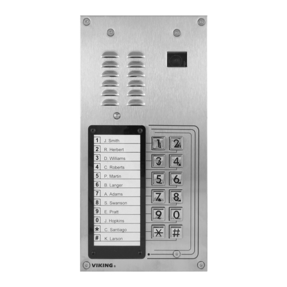
Vandal Resistant VoIP Entry Phone System with Built-In
Directory, 12 Button Auto Dialer and Analog Video Camera
The K-1205-IP is a durable and attractive handsfree phone for apartment and residential door entry
applications requiring a vandal resistant VoIP speaker phone with integrated analog color video camera.
The K-1205-IP phone is designed to provide quick and reliable handsfree communication for SIP VoIP
phone systems or cloud based service providers. The K-1205-IP can be programmed from any PC on the
same LAN or remotely using a Static IP Address. The K-1205-IP entry phone can dial up to 12
programmable numbers and 12 rollover numbers. The brushed stainless steel faceplate has a built-in 12
resident directory with a waterproof, scratch resistant lens and 12 buttons for single push auto-dialing of a
tenant's phone number or business extension.
When the K-1205-IP phone is connected to an apartment or business tenant, a built-in contact closure may
be activated to control an electric gate or door strike. Up to 1,000 keyless entry codes may be programmed,
providing tenants with keyless entry. A 26 bit Wiegand input is provided for adding an optional proximity
card reader with capacity to program up to 1,000 card numbers. Keyless entry codes and card numbers
can be programmed to only allow access at specific times and/or day of the week. The K-1205-IP includes
a request for exit (REX) input and also offers event logging with time and date stamp .
The K-1205-IP-EWP shares all of the features of the K-1205-IP in addition to Enhanced Weather Protection
(EWP) for outdoor installations where the unit is exposed to precipitation or condensation. EWP products
are designed to meet IP66 standards and may feature foam rubber gaskets, sealed connections, gel-filled
butt connectors, as well as potted circuit boards. For more information on EWP, see DOD 859.
• Vandal Resistant Features: 14 gauge louvered 316 stainless steel faceplate with
permanent laser etched graphics. Speaker/mic screen. Heavy duty metal keypad
buttons and T-10 Security Torx drive mounting screws.
• Weather Resistant Features: Marine grade 316 stainless steel faceplate and screws.
Keypad internally sealed per IP67. Mylar speaker. Self-draining mic mount. Faceplate,
mic and speaker gaskets.
• Built-in high resolution analog NTSC color video camera with wide viewing angle,
tilt/swivel adjustments and wide operating temperature: -40°F to 140°F
• Two sets of SPDT 2 Amp relay contacts for door/gate or camera control
• Optional RC-4A for Secure Remote Relay Control, see DOD 582
• Blue "Call /Status" LED indicator
• SIP compliant (see page 2 for compatible SIP servers and IP phone systems)
• Outbound Proxy, Authentication ID, Peer to Peer, VLAN Tagging
• PoE powered (class 2, <6.5 Watts)
• Automatic Noise Canceling (ANC) feature for operation in noisy environments
• Viking's proprietary VOX switching eliminates the need for "Push to Talk" mode
• Network downloadable firmware
• 26 bit Wiegand input for optional proximity card readers, see DOD 221 and 228
• 26 Bit Wiegand output connect to card reader input of an Access Control System
Applications
• Residential Gate Entrance
• Courtesy Assistance Phone
• Customer Service Phone
• Automated Teller (ATM) Phone
Information: 715-386-8861
www.VikingElectronics.com
PRODUCT
MANUAL
Features
• Door Entry Phone
• Apartment Entry Phone
• Kiosk Phone
VoIP Entry Phone System with
12 Button Auto Dialer & Camera
"Brushed 316 Stainless Steel"
(similar to brushed nickel)
• Programmable to speed dial up to 12 numbers
• Cycles to rollover phone number on busy or no-answer
• Program up to 1,000 keyless entry codes and/or proximity card numbers
• Keyless entry codes and proximity card numbers can be programmed to only allow
access at specific times and days of week
• Event logging with time and date stamp
• Optional Enhanced Weather Protection (EWP), EWP products are designed to meet IP66
Ingress Protection Rating, see DOD 859
• Hangs up on busy signal, time-out or touch tone command
• Remotely programmable
• Extended temperature range -40°F to 140°F
• Programmable volume adjustments for microphone and speaker
• Selectable auto-answer feature for monitoring
• Flush mount with included Zinc plated steel rough-in box,
• Surface mount using an optional VE-5x10 surface mount box (not included, see DOD 424)
• Optional LRR-4 Long Range RFID Receiver, see DOD 226
• Optional VE-LIGHT kit to illuminate the front panel at night, see DOD 428
• Diagnostics for testing microphone, speaker and relays
Specifications
Power: PoE class 2 (<6.5 Watts)
Dimensions: Overall: 5" x 10" x 2.5" (127mm x 254mm x 63.5mm)
Rough-in box: 4.5" x 9.12" x 2.5" (114mm x 232mm x 64mm)
Shipping Weight: K-1205-IP: 4.3 lbs (1.95 kg), K-1205-IP-EWP: 4.5 lbs (2.04 kg)
Operating Temperature: -40°F to 140°F (-40°C to 60°C)
Humidity - Standard Products: 5% to 95% non-condensing
Humidity - EWP Products: Up to 100%
Audio Codecs: G711u, G711a, G722
Network Compliance: IEEE 802.3 af PoE, SIP 2.0 RFC3261, 100BASE-TX with auto cross over
Regulatory Compliance: CE, FCC Part 15 and Canada ICES-003 Class A
Connections: (1) RJ45 10/100 Base-T, (16) gel-filled butt connectors
See Camera Specifications on page 3.
K-1205-IP Series
May 29 , 2020
K-1205-IP
K-1205-IP
(shown in optional VE-5x10-SS
surface mount box)
Installation requires the assistance of a
!
Network Administrator / IT Technician.
Advertisement
Table of Contents

Related Manuals for Viking K-1205-IP Series


Summary of Contents for Viking K-1205-IP Series
- Page 1 • Automatic Noise Canceling (ANC) feature for operation in noisy environments • Optional LRR-4 Long Range RFID Receiver, see DOD 226 • Viking’s proprietary VOX switching eliminates the need for “Push to Talk” mode • Optional VE-LIGHT kit to illuminate the front panel at night, see DOD 428 •...
- Page 2 VoIP SIP System Compatibility For compatibility and vendor specific detailed configuration instructions, see the Viking VoIP SIP System Compatibility List, DOD 944. To open and download this PDF file: Scan the QR code below to open 1. Go to www.vikingelectronics.com...
-
Page 3: Camera Specifications
Right 30° correct video color in outside applications. The standard camera is NOT compatible with IR illuminators. If IR illumination is required, you will need to replace the existing camera with a Viking model VCAM-1IR. For more information, see DOD 190. -
Page 4: Features Overview
PoE LAN Port 10/100, For connecting optional Proximity Card Readers, Green PoE Class 2 (<6.5 Watts): see Viking models above (not included) or program Connect to your LAN via + Red as a output to connect to the card reader input of an... - Page 5 IP video Twisted foil and braided shield encoder (Axis M7011), etc. Yellow/Red ** Note: For ease of installation, a Viking Female "F" to Black Wire Converter Cable can be used (Part # 261217) or - Black (GND) "BNC" to wire converter cable (Part # U213510) can be ** Female "F"...
-
Page 6: Installation And Mounting
When mounting a PRX-3 in close proximity of the K-1205-IP (ie: using a PRX-3-MK-GNP mounting kit), you must set “Relay 2 mode” to “Alarm” in Programming and wire as shown below. When using the PRX-3 with any Viking Entry System/Controller, the provided 12V DC 500mA power adapter and 2200µF bi polar capacitor should be used. - Page 7 2. Click K-1205-IP in the search results 3. Scroll down the page to Downloads, click IP Programming Software 4. Install the programming software by saving or opening the file and then clicking on setup Viking IP Programming.exe 5. Follow the prompts on your screen to complete software installation.
- Page 8 “,” button for 5 seconds (2 beeps will then be heard) or by clicking the “Mute Alarm Until Next Failure” button in the Viking IP programming software. The LED will continue to flash allowing you to trouble shoot the failure.
- Page 9 Step 1. Series phone to be programmed. The window in the upper left corner of the menu will show you each K-1205-IP Series phone that is connected to that Step 2. LAN. Select the unit with the same MAC address shown on the label located on the top of the Ethernet connector on the K-1205-IP Series phone.
- Page 10 D. Configuring K-1205-IP VLAN Settings Step 1. Click on the “VLAN” tab Step 2. Disable or enable VLAN tagging by setting the value of “VLAN Tagging”. Step 3. Set the VLAN tag ID by selecting an integer (1 to 4094) in “ID for all packets”. Set the Priority Code Point (PCP) value for all not SIP and RTP packets in the “PCP for all packets”...
- Page 11 Programming Features Index DESCRIPTION Section Page Connect/Disconnect VLAN Settings Unit Name SIP Server Peer to Peer Settings Outbound Proxy Authentication ID Register Fails Phone Number Database Event Log Entry Code Database Keyless / Card Logging Security code (factory set to 845464) Access Code (1 - 6 digits, blank = disabled, factory set to 123456) Weigand Direction Select Time Zone...
-
Page 12: Programming Features
Programming Features 1. Unit Name Up to a 31 character unit name can be assigned to the K-1205-IP Series Phone being programmed. 2. SIP Server Enter the IP address or URL of your SIP server or service provider in this field. The SIP server IP address is limited to 74 characters. - Page 13 7. Phone Number Database Clicking on the “Phone Number Database” button will open a screen allowing you to program all the Tenants Name’s, Speed Dial Numbers, and Primary and Roll Over phone numbers. Tenant names are stored locally on the PC and are not uploaded.
-
Page 14: Event Log
8. Event Log The Event Log button is used to open the Event Log screen. The Event Log screen shows you the time and date of each event, the event type, relay action (which door/gate was opened or closed), entry code index and phone number index with tenant name. -
Page 15: Security Code
9. Entry Code Database Clicking on the “Entry Code Database” button will open the Entry Code Database screen. The Entry Code Database will then download, this can take over a minute. The Entry Code Database will allow you to program the Relay Function, Relay 1 or 2, once only (one time use only), Entry Type (Card, Keyless or both), Keyless Code, Proximity Card #, Facility Code, Day of week, Time of Day and Tenant Name. -
Page 16: Select Time Zone
With relay 1 and/or 2 set to “Internal” the K-1205-IP will activate its on board relays for doorstrike / gate control. Relay 1 and/or 2 should be set to “External” for higher security installations when using a Viking model RC-4A remote relay controller to activate the doorstrike / gate controller (see page 23). - Page 17 17. Relay Mode Doorstrike Mode (Factory Setting): When programmed for Doorstrike Mode the relay will momentarily activate for the preprogrammed relay activation time after detecting the correct relay activation command (one or two digit touch tone) from the called party. Outbound Call Mode: When programmed for Outbound Call Mode the relay will activate continuously for the duration of any outbound call from the Entry phone.
- Page 18 22. Relay Latch Commands When set to “Enabled” the Remote Access Operation Commands to Un-Latch or Latch the relay are enabled. When set to “Disable” the Remote Access Operation Commands to Un-Latch or Latch the relay are disabled. Disabling the Latch commands can be useful in applications where you want to eliminate the possibility of inadvertently entering a latch command leaving a gate open/closed, etc.
- Page 19 30. Inbound Call Mode The Inbound Call Mode determines how the K-1205-IP handles incoming SIP calls. One option is to auto answer a SIP call to transmit a page, control the relay or listen to transmit audio from the microphone. Another option is the silent monitor mode, which allows callers to listen to the transmit audio from the microphone.
- Page 20 “Update IP” button. You can then browse to the folder that contains the PIP file for updating the unit’s IP firmware. This method is typically only used when Viking Technical Support has sent you updated IP firmware. 38. Unit Firmware If new K-1205-IP firmware is available, after opening the programming software a pop window will come up asking you if you would like to update firmware.
-
Page 21: Operation
42. Diagnostics The Diagnostics section in the Viking IP Programming can be used to test the functionality of the two relays, read current relay status, perform mic/spkr diagnostics, or to display information on the last card or fob detected by the card reader. -
Page 22: Troubleshooting
” button on the keypad for 5 seconds or by clicking the “Mute Alarm Until Next Failure” button in the Viking IP Programming Software (see section 35 on page 20). The error beeps automatically re-enable once the unit is registered, to alert of any new problems that arise. - Page 23 The front panel of the K-1205-IP is mounted using security Torx screws to help prevent intruders from removing the panel and accessing the on board door strike/gate control relays. For applications requiring additional security, a Viking model RC-4A remote relay controller can be used. The relay controller is mounted securely inside the building and connected to the same LAN as the K-1205-IP.
-
Page 24: Related Products
Caution: Handsfree phones are not suitable for noisy applications (see “Important” on page 2). For more information on Viking Surface Mount Boxes and Pedestals, see DOD 424. Add Panel Lighting to Your Viking VoIP Entry Phone... - Page 25 Relays can be toggled on or off, or user-programmed timed closures can be activated. The RC-4A can be configured to work as a remote relay for Viking VoIP series entry phones, controlling door strikes and gates when a remote relay is required for security reasons. It can also be programmed to send an email or text message in response to a change in one or more of the sensor inputs.
-
Page 26: Warranty
TWO YEAR LIMITED WARRANTY Viking warrants its products to be free from defects in the workmanship or materials, under normal use and service, for a period of two years from the date of purchase from any authorized Viking distributor. If at any time during the warranty period, the product is deemed defective or malfunctions, return the product to Viking Electronics, Inc., 1531 Industrial Street, Hudson, WI., 54016.
Need help?
Do you have a question about the K-1205-IP Series and is the answer not in the manual?
Questions and answers