Advertisement
Quick Links
Installation Instructions
Original Instructions
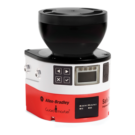
SafeZone 3 Optics Cover
Catalog Numbers 442L-SZNMZCP, 442L-ASZNCPW
Safety
WARNING: Risk of ineffectiveness of the protective device.
Failure to observe these instructions can result in failure of
the protective device: persons or parts of the body to be
protected cannot be detected. During operation, the safety
laser scanner constantly measures the degree of
contamination of the optics cover. For a new optics cover to
function perfectly, an optics cover calibration has to be
implemented initially. This optic cover serves as a reference
for contamination measurement (status = uncontaminated).
• Conduct an optics cover calibration with the 442L Add-on
Profile (AOP) configuration software every time the cover of the
SafeZone™ 3 safety laser scanner is replaced.
• Conduct the optics cover calibration at room temperature
(10...30 °C [50...86 °F]).
• Only conduct the optics cover calibration with a new optics
cover.
• Make sure that the entire system is clear of contamination
when the calibration is conducted.
IMPORTANT
• The optics cover of the safety laser scanner is an
optical component. Make sure that the optics cover
does not become dirty or scratched during unpacking
and mounting. Prevent fingerprints on the optics cover.
Wear the gloves supplied with the new optics cover
during replacement.
• Only qualified safety personnel may replace the optics
cover in a dust- and dirt-free environment.
• Never replace the optics cover during continuous
operation, as dust particles could penetrate into the
safety laser scanner.
• You must prevent contamination on the inside of the
optics cover, for example due to fingerprints.
• Do not use an additional sealant, such as silicone, for
sealing the optics cover. Any vapors that are created
may damage the optical components.
• Mount the optics cover according to the following
instructions, to achieve IP65 leak tightness of the
housing.
• Use new optics covers exclusively as a replacement.
• You must provide ESD protection during the
replacement of the optics cover.
• The IP65 enclosure rating is only valid if the safety laser
scanner is closed and the safety plug is mounted.
Replace the Optics Cover
Figure 1 - Attach the Optics Cover (Use T10 Torx Bit)
Tools Required:
• TX10 torque wrench
1.
Confirm that the environment is clean and clear of fog, moisture, and dust.
2.
First, clean the safety laser scanner from the outside, so that no foreign
bodies penetrate into the open device.
3.
Unscrew the mounting screws (1 in
4.
Slowly and carefully detach the optics cover from the safety laser scanner.
If the optics cover seal sticks to the safety laser scanner, carefully detach
the optics cover using a screwdriver.
5.
If necessary, remove contamination from the sealing groove and the
bearing surface of the safety laser scanner. Use residue-free plastic
cleaners.
6.
Check whether the mirror on the motor is dirty and, if necessary, remove
dirt with an optic brush.
7.
Set 1.0 N•m (8.85 lb•in.) tightening torque on the torque wrench.
8.
During the following steps, wear the gloves that are supplied with the new
optics cover.
9.
Take the new optics cover out of the packaging and remove the protective
cap of the seal.
10. Remove any remaining packaging, if necessary.
11.
Carefully push the optics cover over the mirror. Make sure that the optics
cover does not touch the mirror.
12. Place the optics cover onto the safety laser scanner. Make sure that the
optics cover rests over the whole area without any gaps.
13. Screw in the new mounting screws (1 in
14. Tighten the screws with the set tightening torque of 1.0 N•m (8.85 lb•in.)
15. Verify that the optics cover is clear of dirt and damage.
16. Recommission the safety laser scanner, see publication 442L-UM008.
1
1
1
1
Figure
1) for the optics cover.
Figure
1).
Advertisement

Related Manuals for Rockwell Automation Allen-Bradley Guard master Safezone 3 442L-SZNMZCP


Summary of Contents for Rockwell Automation Allen-Bradley Guard master Safezone 3 442L-SZNMZCP
- Page 1 Installation Instructions Original Instructions SafeZone 3 Optics Cover Catalog Numbers 442L-SZNMZCP, 442L-ASZNCPW Safety Replace the Optics Cover Figure 1 - Attach the Optics Cover (Use T10 Torx Bit) Tools Required: WARNING: Risk of ineffectiveness of the protective device. • TX10 torque wrench Failure to observe these instructions can result in failure of the protective device: persons or parts of the body to be protected cannot be detected.
- Page 2 Rockwell Otomasyon Ticaret A.Ş. Kar Plaza İş Merkezi E Blok Kat:6 34752 İçerenköy, İstanbul, Tel: +90 (216) 5698400 EEE Yönetmeliğine Uygundur Allen-Bradley, expanding human possibility, Guardmaster, Rockwell Automation, and SafeZone are trademarks of Rockwell Automation, Inc. Trademarks not belonging to Rockwell Automation are property of their respective companies.