Table of Contents
Advertisement
4028051/7
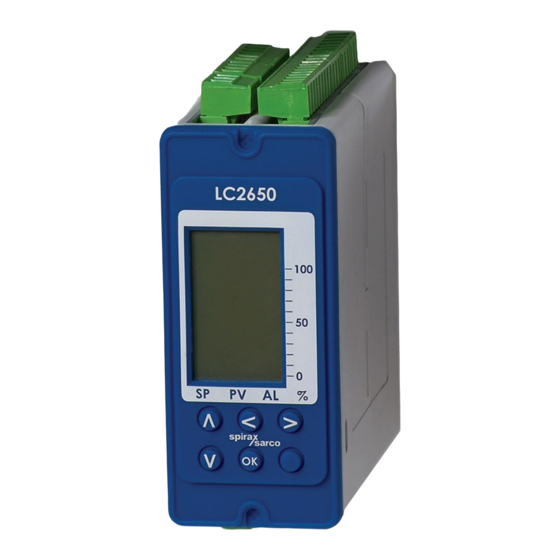
LC2650
Level controller
Installation and Maintenance Instructions
LC2650
100
50
0
%
SP
PV
AL
OK
IM-P402-128
EMM Issue 7
1. Safety information
2. User instructions and
delivery information
3. System overview
4. Mechanical
installation
5. Electrical installation
6. Commissioning
- Quick set-up
- Full
7. Communications
8. Maintenance
9. Fault finding
10. Technical information
- Default settings
11. Appendix
- Summary of the
Modbus protocol
12. Menu map
© Copyright 2017
Printed in GB
Commissioning password
Current legislation states that in order to prevent tampering and potentially
hazardous programming errors, access to the pass codes required to enter
commissioning mode should only be available to qualified and trained personnel.
Enter commissioning
This is done from the run mode by pressing and holding down the
The run mode display will disappear and the display will show 'PASS CODE' with '8888' at
the bottom right corner of the screen. The flashing leading digit indicates the position of the
cursor. The default, or factory set pass code is 7452 but this can be changed from within
the commissioning mode. The pass code can be entered by using the
to increase or decrease the flashing value and the
Pressing the
button will enter the pass code. If an incorrect pass code is used, the display
OK
automatically returns to the run mode.
This page MUST be removed after
commissioning and kept in a safe,
access controlled location.
button for 5 seconds.
OK
and
buttons
and
buttons to move the cursor.
IM-P402-128 EMM Issue 7
Advertisement
Table of Contents

Related Manuals for Spirax Sarco LC2650


Summary of Contents for Spirax Sarco LC2650
- Page 1 Current legislation states that in order to prevent tampering and potentially hazardous programming errors, access to the pass codes required to enter commissioning mode should only be available to qualified and trained personnel. LC2650 Enter commissioning Level controller This is done from the run mode by pressing and holding down the button for 5 seconds.
- Page 2 IM-P402-128 EMM Issue 7 IM-P402-128 EMM Issue 7...
-
Page 3: Safety Information
This product is suitable for Heavy Industrial Environments. A fully detailed EMC assessment has been made and has the reference number UK Supply BH LC2650 2008. The product may be exposed to interference above the limits of Heavy Industrial Immunity if: The product or its wiring is located near a radio transmitter. - Page 4 Static precautions (ESD) Static precautions must be observed at all times to avoid damage to the product. Level control and level limiting products in steam boilers Products / systems must be selected, installed, operated, and tested in accordance with: Local or National standards and regulations. Guidance Notes, (Health and Safety Executive BG01 and INDG436 in GB).
- Page 5 Symbols Equipment protected throughout by double insulation or reinforced insulation. Functional earth (ground) terminal, to enable the product to function correctly. Not used to provide electrical safety. Clean earth / ground. Safety earth. Caution, risk of electric shock. Caution, risk of danger, refer to accompanying documentation. Optically isolated current source or sink.
- Page 6 Determine the correct installation situation and direction of fluid flow. iv) Spirax Sarco products are not intended to withstand external stresses that may be induced by any system to which they are fitted. It is the responsibility of the installer to consider these stresses and take adequate precautions to minimise them.
- Page 7 1.16 Returning products Customers and stockists are reminded that under EC Health, Safety and Environment Law, when returning products to Spirax Sarco they must provide information on any hazards and the precautions to be taken due to contamination residues or mechanical damage which may present a health, safety or environmental risk.
-
Page 8: All Rights Reserved
Spirax-Sarco Limited. 2.1 General description The Spirax Sarco LC2650 is a level controller for conductive liquids. It has two alarm channels that can be independently configured high or low. Warning: The minimum conductivity when used with the LP20, PA20 or PA420 is 5 μS / cm or 5 ppm. -
Page 9: Front Panel
2.2 Front panel The front panel has an LCD graphics display and five-button keypad. LC2650 Graphic display Horizontal arrows are used to toggle between the Bar graph Scroll up menus and the Trend graph Scroll down menus Clears any errors or alarms... -
Page 10: Lcd Display
2.4 LCD display The display is divided into three sections: Four large digits, displaying the process variable and control parameters. Information line. Displays the various control states and process units. Three bar graphs, which show a percentage of full scale (percentage of the gauge glass). After initially applying power to the product, it will automatically enter its run mode. - Page 11 Highest process variable reached This can be reset by entering the commissioning mode. Current process variable Graphical representation of the process variable in terms of percentage of full scale. Lowest process variable This can be reset by entering the commissioning mode Fig.
- Page 12 Two element control - Split set point The Split Set Point is visible only if a STEAM OFFSET percentage is selected in the INPUT menu. 100% PV has increased due to sudden high steam demand causing feedwater valve to close. SP PV AL Fig.
- Page 13 100% Set Point raised by steam meter compensation Offset Original Set Point SP PV AL Fig. 7 Graphics display with steam meter compensation A second display is superimposed on the SP graph to show the offset caused by the action of the steam meter.
-
Page 14: Trend Screen
Trend screen A trend graph appears if the button is pressed in run mode. buttons are used to toggle between the run mode and trend graph. The trend graph displays a record of the variation in level over a set time. The most recent event / value is to the left of the graph. - Page 15 2.5 Information line The information line will show level and will alternate with information about alarms and the pump or valve status. Example of valve status: ä ä LEVEL% VALVE OPENING If an alarm occurs, the pump or valve status will not show. 'ALARM' will be shown first followed by the type of alarm.
- Page 16 2.6 View parameter mode Press the button or downward button to view and step through the parameters selected. Each parameter will remain on view for a further 2 minutes unless a button is pressed again. After initially applying power to the product, it will automatically enter its run mode. The current level (percentage) will be displayed.
- Page 17 AL1 DEL S Shows the delay in seconds (damping effect for turbulent conditions), chosen for ALARM 1. AL2 LOW% Alarm 2 is set to a LOW or HIGH water alarm. Its value is a percentage of the gauge glass. AL2 HYST% Shows the hysteresis selected for alarm 2.
-
Page 18: Receipt Of Shipment
Each carton should be unpacked carefully and its contents checked for damage. If it is found that some items have been damaged or are missing, notify Spirax Sarco immediately and provide full details. In addition, damage must be reported to the carrier with a request for their on-site inspection of the damaged item and its shipping carton. -
Page 19: System Overview
3. System overview 3.1 Function The product compares the input signals with the Set Point to control the water level in the boiler tank, or vessel, by operating a pump, valve, or solenoid. On / off control Pump control. Two alarm outputs. 4 - 20 mA level retransmission output (isolated). -
Page 20: Other Features
To prevent unwanted or inadvertent changes being made, all commissioning parameters are protected with a pass code. The commissioning Engineer can change this. The product can communicate via an infra-red link between adjacent controllers (Spirax Sarco Products only) - see Section 7 'Communications'. - Page 21 TDS level. There will also be a difference in level between the boiler and the gauge glass under different firing conditions and steam demand. LC2650 Steam meter Level probe Pneumatic valve Fig.
- Page 22 Under certain conditions where the boiler feedwater pressure varies considerably, perhaps due to other boilers drawing water, three-element control is used. A water flowmeter is added to compensate for variations in flow due to pressure variations. LC2650 Steam meter Level probe...
-
Page 23: Mechanical Installation
4. Mechanical installation Note: Read the 'Safety information' in Section 1 before installing the product. The product must be installed in a suitable industrial control panel or fireproof enclosure to provide impact and environmental protection. A minimum of IP54 (EN 60529) or Type 3, 3S, 4, 4X, 6, 6P and 13 (UL50/NEMA 250 ) is required. - Page 24 4.3 Installation on a chassis plate: Drill holes in chassis plate as shown in Figure 12. Fit unit to chassis plate and secure with 2 screws, nuts and washers, using the slots provided at the top and bottom of the case. Warning: Do not drill the product case or use self-tapping screws.
- Page 25 Fig. 12 Ø 4.2 mm Ø 4.2 mm Chassis plate / panel - 10 mm cutout diagram 45 mm 112 mm 92 mm 22.5 10 mm Ø 4.2 mm Ø 4.2 mm 67 mm 120 mm 8 mm 112 mm 120 mm IM-P402-128 EMM Issue 7...
-
Page 26: Electrical Installation
Use only the connectors supplied with the product, or spares obtained from Spirax Sarco Limited. Use of different connectors may compromise product safety and approvals. Ensure there is no condensation within the unit before installing and connecting the power. - Page 27 It is important that the cable screens are connected as shown in order to comply with the electromagnetic compatibility requirements. 10. All external circuits must meet and maintain the requirements of double / reinforced installation as stated in IEC 60364 or equivalent. 11.
- Page 28 5.2 Mains wiring notes: 1. Read Section 5.1 - 'General wiring notes', before attempting to wire the supply to the product. 2. The wiring connections are identified on the terminal plugs. 3. Fuses should be fitted in all live conductors, see Figures 13 and 14. 4.
- Page 29 Alarm Input Norm 3 A fuse 22 21 Alarm 2 relay Caution live terminals Alarm 1 relay Control relay ac supply 3 A fuses Norm 3 A fuse Input Input Alarm See Mains wiring notes Modulating control Control valve electric actuator (valve motor drive) ON / OFF control...
-
Page 30: Probe Wiring
5.4 Probe wiring The maximum cable length for all transducers is 100 m (328 ft). Note: It is essential to select the correct sensitivity on the PA20 preamplifier, (see the PA20 Installation and Maintenance Instructions for details). 0-20 mA or 4-20 mA 4-20 mA output display Connect to... - Page 31 50 51 52 53 54 55 50 51 52 53 54 Connect to a clean earth Another 53 54 local in the LC2650 Self powered panel 4-20 mA level transmitter Fig. 18 4 - 20 mA level transmitter LC2200 LT2010,...
- Page 32 5.6 Wiring diagram for the UL version of the PA20 PA20 preamplifier and LP20 capacitance probe (see PA20 and LP20 Installation and Maintenance Instructions). Level input (s) +24V Screen Connect to clean earth local to the panel Terminal box See PA20 IMI for sensitivity selection Flying leads supplied with the UL approved PA20 (approximately 12") Capacitance level probe...
- Page 33 5.7 EIA / TIA-485 communication wiring diagram The product can be connected as a slave to a two or four-wire EIA / TIA-485 multi-drop network. Remove link between terminals 90 and 91. Slave(s) (Boiler controller) H / D H / D Common Earth wiring...
- Page 34 Slave(s) (Boiler controller) H / D H / D Add link between terminals 91 and 90 Common Earth See wiring notes Master Fig. 22 RS485 / Modbus half-duplex circuit (view from the top) EIA / TIA-485 wiring notes continued: The bus common must be connected directly to protective ground / earth at one point only. Generally this point is at or near the master device.
-
Page 35: General Information
If during commissioning, the buttons are not pressed for over 5 minutes, the controller will revert to run mode and an error will occur. If the commissioning was incomplete the controller may not provide the correct control. LC2650 Graphic display Exit sub-menus and shift... - Page 36 6.2 Commissioning mode navigation After the correct pass code has been entered the display shows: MODE To exit the commissioning mode at any stage, press and hold the button to return to the run mode. Press the buttons to scroll through the first level menus. Press the button to enter a particular sub-menu.
- Page 37 6.3 Commissioning - Quick set-up This section allows the user to carry out the minimum commissioning necessary to operate the system. It accepts the defaults set in the factory, so will only work if the original default settings have not been altered - see the default settings in Section 10. Settings can then be tailored to suit the individual requirements of the customer / application if required.
- Page 38 6.4 Commissioning - Full Enter commissioning as stated in Section 2 and follow the main menu structure to make the changes required. 6.4.1 Main menu structure This IMI indicates your position within the menu by showing the parameter in bold, but also shows the path, so it is easy to see where you are within the menu structure, e.g.: INPUT (main menu) LEVEL (first sub-menu )
-
Page 39: Mode Sub-Menu
6.4.2 MODE sub-menu Entering this menu (press ) allows the user manual drive the valve or pump to assist in commissioning: Modulating control: CLOSED: Drive valve closed OPEN: Drive valve open STOP: Stop the valve and leave in current position. ON/OFF control: Pump on: Switches the pump on... - Page 40 6.5 INPUT sub-menus 6.5.1 INPUT LEVEL sub-menu INPUT Sets sensor input type: 1 - 6 V for probes LP20 and PA20, or LEVEL ä 4-20 mA for probes LP20 and PA420 or DP transmitter SENSOR INPUT User can select an alarm if the input signal is out of range. LEVEL Select ON or OFF.
- Page 41 Note: Grey tint indicates features only available under certain conditions. 6.5.2 INPUT POT sub-menu Enables the VMD feedback potentiometer to be calibrated. INPUT INPUT – POT – CAL – MIN The controller will automatically drive the valve to the closed position.
- Page 42 Note: Grey tint indicates features only available under certain conditions. 6.5.4 INPUT WATER METER sub-menu INPUT Enables the feedwater meter (water meter) to be selected. W/METER Only available if proportional control is selected. Only available if a water meter is selected. Enables the INPUT water meter to be scaled so that it reads 100% at the maximum boiler output.
- Page 43 Note: Grey tint indicates features only available under certain conditions. 6.5.6 OUTPUT DRIVE sub-menu OUTPUT Sets type of valve control - ON OFF or PROP DRIVE ä (proportional). CONTROL OUTPUT DRIVE Selects PUMP IN or PUMP OUT, i.e. fill or empty control. ACTION OUTPUT Only available if proportional control is selected.
- Page 44 6.5.7 OUTPUTS RETRANS Enables the water level to be remotely sensed, recorded or displayed. 0 or 4 mA This menu enables the user to choose between a 0 or 4 mA minimum setting. Default 4 mA. (4 mA is used so that a 0 mA signal will act as an indication of a fault). 4 mA and 20 mA retransmission levels are set as a percentage of the gauge glass, normally 4 mA = 0% and 20 mA = 100, though this can be changed if required.
- Page 45 6.5.10 ALARM 1 and ALARM 2 menus Both alarm menus are identical. ALARM 1 or Sets high or low alarm. Both alarms can be set to high or ALARM 2 low, or one high, one low. Regulations apply to boiler low ä...
- Page 46 6.5.11 Test menu Allows access to the diagnostic features All display pixels will be activated - black background. Press TEST down button to go to TEST INPUT. Press the left button to ä DISPLAY cancel the test and step to SW.VER. TEST Displays the input signal on each input.
- Page 47 6.5.12 TEST INPUT sub-menu TEST INPUT Displays current temperature of internal components in °C. ä INT TEMP TEST INPUT Displays mA or Volts input from the level sensor. TEST Displays voltage input from the valve feedback INPUT potentiometer (if fitted). FEEDBACK TEST INPUT...
- Page 48 6.5.13 TEST OUTPUT sub-menu Test parameters will reset to the normal run mode value or state either after 5 minutes or by selecting the TEST / OUTPUT / CANCEL. TEST Tests 0/4-20 mA output signal - e.g. to BMS. OUTPUT ä...
- Page 49 6.5.14 SOFTWARE VERSION sub-menu SW VER Allows the software version to be viewed - useful for fault diagnosis. 6.5.15 PASS CODE sub-menu SET PASS Allows the default pass code to be changed to a user-defined code. It is important that if the default pass code is changed that the new code is noted and kept safe.
-
Page 50: Infrared (Ir)
It enables the parameters of up to seven products to be passed to a product fitted with RS485 (products with a graphics display). The LC2650 can be designated a master or a slave unit. The product connected to the RS485 networks must be fitted on the left of all the slaves fitted to the IR bus (Figure 25) and have ‘master’... -
Page 51: Level Controls
Boiler water level controls and level alarms, however, do require testing and inspection. General guidance is given in Health and Safety Executive Guidance Notes BG01 and INDG436. For specific instructions for the Spirax Sarco system please see separate literature. Cleaning instructions Use a cloth dampened with tap / de-ionized water / isopropyl alcohol. -
Page 52: Fault Finding
9. Fault finding WARNING: Before fault finding read the Safety information in Section 1 and the General wiring notes in Section 5.1. Please note that there are hazardous voltages present and only suitably qualified personnel should carry out fault finding. The product must be isolated from the mains supply before touching any of the wiring terminals. - Page 53 Symptom Action 1. Switch off the mains supply to the product. 2. Disconnect all signal wires. 3. Switch the mains supply on: If symptoms are still present, return the product for examination. 4. Replace each signal wire in turn until the fault occurs. 5.
-
Page 54: Error Message
9.3 Operational error messages Any operational errors that occur will be displayed in the run mode, on the alarms and errors screen. Error Cause Action message 1. Remove the power from the product. There has been a 2. Check that all the wiring is correct. loss of power to 3. -
Page 55: Technical Information
10.2 Returning faulty equipment Please return all items to your local Spirax Sarco representative. Please ensure all items are suitably packed for transit (preferably in the original cartons). Please provide the following information with any equipment being returned: 1. - Page 56 10.4 Environmental General Indoor use only Maximum altitude 2 000 m (6 562 ft) above sea level Ambient temperature limits 0 - 55 °C (32 - 131 °F) 80% up to 31 °C (88 °F) decreasing linearly to 50% at Maximum relative humidity 40 °C (104 °F) Overvoltage category...
- Page 57 10.5 Cable / wire and connector data Mains and signal connector Rising clamp plug-in terminal blocks with screwed Termination connectors Cable size 0.2 mm² (24 AWG) to 2.5 mm² (14 AWG). Stripping length 5 - 6 mm Please note: Use only the connectors supplied by Spirax-Sarco Limited – Otherwise Safety and Approvals may be compromised.
- Page 58 10.6 Input technical data Level voltage Minimum voltage 0 Vdc or 1 V (with OUTRANGE function selected) Maximum voltage 6 Vdc (absolute maximum = 7 Vdc) Input impedance 28 kΩ Accuracy 5% FSD over operating range Repeatability 2.5% FSD over operating range Resolution 14 bit (0.15 mV approx) Sample time...
-
Page 59: Vdc Supply
10.7 Output technical data 24 Vdc supply Maximum voltage 24 Vdc (nominal) Maximum current 25 mA Ripple voltage 10 mV at 264V, full load 4-20 mA(s) Minimum current 0 mA Maximum current 20 mA Open circuit voltage 19 Vdc (maximum) Resolution 1% FSD Maximum output load... -
Page 60: Programming Parameters
10.8 Programming parameters The default settings in this table can be used as a ‘quick start’ guide. See Section 6. 10.8.1 MODE MENU Proportional control allows the valve to be manually opened, closed or stopped Ranges OPEN, CLOSED or STOP Default STOP In ON / OFF control... - Page 61 LEVEL - CTL BAND (Control Band) 5 - 100 (Interactive with steam offset and SP. control band Ranges cannot exceed 100%) Default Resolution (steps) Units LEVEL - SP (Set Point) 3 - 97 (Interactive with steam offset and SP. control band Ranges cannot exceed 100%) Default...
- Page 62 10.8.3 OUTPUT MENU COMMS - ADDRESS (MODBUS communication) DRIVE - CONTROL Ranges PROP or ON/OFF Default PROP DRIVE - ACTION Ranges PUMP IN or OUT Default PUMP IN DRIVE - TYPE Ranges VMD or 4-20 mA Default VMD (Valve Motor Drive) DRIVE - DEADBAND Ranges 5 - 20 (Relay hysteresis = 1%)
- Page 63 POSITION (positioner) - 0 or 4 mA Ranges 0 or 4 mA Default 4 mA POSITION (positioner) - SET - 4 mA Ranges 0 - 100 Default Units POSITION (positioner) - SET - 20 mA Ranges 0 - 100 Default Units POSITION (positioner) - CHECK - 4 mA Default...
- Page 64 LEVEL% Ranges 0 - 100 (Interactive with HYST) Default 85% (HIGH), or 20% (LOW) Resolution (steps) Units HYST (Hysteresis) Ranges 0 - 100 (Interactive with HYST) Default Resolution (steps) Units DELAY Ranges 0 - 99 Default Resolution (steps) Units Seconds LATCH Ranges OFF or ON...
- Page 65 INPUT - FLOW (Signal from water meter) Ranges 0.00 - 22.73 Resolution (steps) 0.01 Units dc milliamps INPUT - STEAM (Signal from steam meter) Ranges 0.00 - 22.73 Resolution (steps) 0.01 Units dc milliamps OUTPUT - RETRANS (Sets the output between 4-20 mA manually) Ranges 4 - 20 mA Default...
-
Page 66: Exception Codes
11. Appendix - Summary of the Modbus protocol Format: Byte Format: Request frame Start 1 bit Address 1 byte Data 8 bit Function code 1 byte Parity 0 bit Start address 2 bytes Stop 1 bit Quantity of registers 2 bytes Cyclic redundancy check (CRC) 2 bytes Total... - Page 67 12. Menu map IM-P402-128 EMM Issue 7...
- Page 68 IM-P402-128 EMM Issue 7...
Need help?
Do you have a question about the LC2650 and is the answer not in the manual?
Questions and answers