
Subscribe to Our Youtube Channel
Related Manuals for Croplands CROPAIR 300


Summary of Contents for Croplands CROPAIR 300
- Page 1 OPERATORS MANUAL CROPAIR 300/600 STOP BEFORE COMMENCING WWW.CROPLANDS.COM.AU operation, ENSURE you read & understand this manual, its contents, and any additional information supplied. LP-OMCROPAIR-A...
- Page 2 Croplands has taken steps to ensure this operator’s manual is as current and as accurate as possible. Due to the ever-changing markets of cropping and farming, Croplands is constantly striving to be at the forefront of innovation and technology. While the information in this manual is considered accurate at the time of writing, Croplands reserves the right to change this information without notice.
-
Page 3: Table Of Contents
CONTENTS SECTION 1 SECTION 5 SECTION 7 IMPORTANT INFORMATION PRE-OPERATION SPRAYING INFORMATION About this manual Safety first Spraywise Terminology Hook up Calibration Before Operating Your Sprayer Confirming Sprayer Functionality Step 1 - ensure equipment is in good working order Warranty Policy Confirming Fan Functionality Step 2 - determining the actual speed of travel Confirm Spraying... -
Page 4: Important Information
This manual provides assembly, setting up, operating and These terms/symbols used throughout Before attempting to use your sprayer, make sure you maintenance instructions for the Croplands Cropair range this manual: read all Operator Manuals for this sprayer including but of sprayers. -
Page 5: Warranty Policy
• the Sprayer’s unique serial number, WARRANTY & PRE-DELIVERY • the Sprayer’s specification sheet, HORTICULTURE • a pre-delivery checklist and • outlines the Croplands Warranty policy. STOP Always contact your Croplands Dealer first and foremost for warranty matters. BEFORE COMMENCING WWW.CROPLANDS.COM.AU... -
Page 6: Safety
This includes the Croplands Operators Safety Manual – as pictured here. MANUAL This manual is available on the Croplands Web site, or for printed versions contact Croplands customer support and ask for part number GP-SAFE-A (or later version if available). WWW.CROPLANDS.COM.AU... -
Page 7: Safety Signs And Decals
All signs and decals for sprayer safety and operation must be maintained in good order and replaced if damaged or missing. Most Croplands labels have a part number printed on the decal to aid identification and replacement. Some examples are shown below. -
Page 8: Product Identification, Shipping & Specification
HL600/800 50 ~ 60 HP Category 2 or 3 linkage connections required. GENERAL SPECIFICATION The Croplands Cropair sprayers featuring Fieni Airblast fans, are available in 2 standard configurations to give the maximum possible spray coverage. HL300/600 300L tank and frame, fitted with an ARVDR50 Controller... -
Page 9: Dimensions Hl300/600
THIS DRAWING IS THE PROPERTY OF CROPLANDS PTY. LTD. AND MUST BE TREATED AS CONFIDENTIAL. REPRODUCTION OF THIS DRAWING (OR PART THEREOF) OR COMMUNICATION OF ITS CONTENTS IS PROHIBITIED WITHOUT THE CONSENT OF CROPLANDS PTY. LTD. WEIGHT: SCALE: 1:15 SHEET 1 OF 1... -
Page 10: Product Features /Familiarisation
SECTION 4 PRODUCT FEATURES / FAMILIARISATION FIENI “AIRBLAST” FANS FIENI 616 MM FAN FIENI 815MM FAN CHASSIS/FRAME LINKAGE CONNECTIONS PUMP & PTO TANKS, LIDS, SIGHT GAUGES, SUMP & DRAIN THE MAIN TANKS FEATURE … THE FLUSHING TANKS …. THE HAND-WASH TANKS …. LP-OMCROPAIR-A... - Page 11 • STAY AWAY from the fan when the tractor is running. The Croplands, Cropair air-blast fans are engineered • DO NOT stay in the working area (air inlet or spray Fan Pitch by Fieni, a global leader in agricultural fan design, outlet) of the sprayer unit.
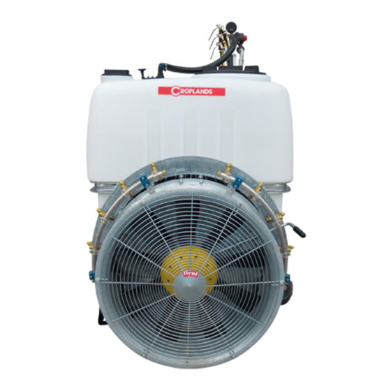
- Page 12 FRONT SPRAYER UNITS D.616-63RDVPL Sprayer unit with nylon fan 616 mm diameter, 9 blades and V1N gearbox. SECTION 4 Fan model: PRODUCT FEATURES / FAMILIARISATION Overview Product image FIENI “AIRBLAST” SPRAY FANS Fieni 616 mm Fan The 300 Litre sprayer uses a Fieni VPL series, 9-bladed, 616 mm diameter, pitch adjustable blades driven via the single speed V1N gearbox.
- Page 13 Ratio 1 1:3.50 1:4.40 Ratio 2 Nozzles to be selected at the time of ordering, either ATR’s or Disc and Cores. Refer to Croplands Buyers Guide for more information on nozzles and nozzle choices.
- Page 14 D.815-42RDVPL Sprayer unit with nylon fan 815 mm diameter, 9 blades and CM12 gearbox. SECTION 4 Assembled Spin Overview Product image PRODUCT FEATURES / FAMILIARISATION Fieni 815mm Fan The 600 Litre sprayer uses a Fieni VPL series, 9-bladed, 815 mm diameter, pitch adjustable blades driven via the dual speed V2C-A gearbox.
- Page 15 Weight 5 kg Nozzles to be selected at the time of ordering, either Ratio 1 1:3.50 ATR’s or Disc and Cores. Ratio 2 1:4.00 Refer to Croplands Buyers Guide for more information on nozzles and nozzle choices.
- Page 16 SECTION 4 PRODUCT FEATURES / FAMILIARISATION CHASSIS / FRAME TANKS, LIDS, SIGHT GAUGES, SUMP & DRAIN Heavy-duty, hot-dipped galvanised frame. The HL300/600 uses a 300 Litre Main tank, 40 Litre Flushing tank, and a 10 Litre Hand wash tank. The 600 Lt frame has an optional slide out rear parking legs. The HL600/800 uses a 600 Litre Main tank, 80 Litre PUMP &...
- Page 17 SECTION 4 PRODUCT FEATURES / FAMILIARISATION THE MAIN TANKS FEATURE … THE FLUSHING TANKS …. • A Pull Drain Valve is positioned at the base of the sump (blue arrow) for simple, fast and complete drainage. • A large lid with a mixing basket. Fill is via the lid / are accessed on the right-hand side of the sprayer.
- Page 18 SECTION 4 PRODUCT FEATURES / FAMILIARISATION Agitation Filtration Controls The agitation system is driven by the pump via single venturi • Lid-strainers / chemical mixing baskets are standard on • Tank selection ball valve (select Main or Flushing tanks). tank agitator (red arrow on previous page) which can all models.
- Page 19 SECTION 4 PRODUCT FEATURES / FAMILIARISATION Factory fitted options Pressure is adjusted by rotating the central red knob. Rotate • The 600 Lt Frame has an optional Fold down step for clockwise to increase pressure. access to the lid or •...
-
Page 20: Pre-Operation
SECTION 5 PRE-OPERATION SAFETY FIRST HOOK UP CONFIRMING SPRAYER FUNCTIONALITY CONFIRMING FAN FUNCTIONALITY CONFIRM SPRAYING SHUT DOWN ADJUSTING FAN BLADE ANGLES USING OPTIONAL ELECTRIC CONTROLLER PRE-OPERATION CHECKLIST LP-OMCROPAIR-A... - Page 21 2. Connect the PTO shaft to the tractor 3. Fit the controller (if applicable). Always park the sprayer in a horizontal position and on firm, level ground. Connecting to the tractor Croplands Cropair sprayers suit Categories I and II tractor linkage connections.
- Page 22 & sprayer dimensions. Follow the controller’s manual for instructions on Croplands Buyers Guide nozzle section or the Nufarm Follow the instructions below to fit the PTO shaft onto the connecting to a suitable (tractor) power source.
- Page 23 SECTION 5 PRE-OPERATION CONFIRMING SPRAYER FUNCTIONALITY 6. Select the water source from MAIN tank. At this stage the pump will be drawing from the main tank and bypassing the pressure regulator / controller straight 7. Make sure the Fan (gearbox) is in the neutral position (yellow arrow).
- Page 24 SECTION 5 PRE-OPERATION CONFIRMING FAN FUNCTIONALITY 1 1. Cycle through all 3 taps for Left and Right Spray Repeat the process while drawing fresh water from the Rings plus the Agitator. All are shown below in Flushing tank. the ON position. Check that all functions are The maximum allowed PTO speed is 540 rpm operating correctly.
- Page 25 SECTION 5 PRE-OPERATION 6. For the initial start-up use low tractor rpm and engage Note; the additional load of the fan running will require the PTO. Don’t “drop the clutch”. a different power setting from the tractor compared to the spray functionality testing.
- Page 26 / chosen operating angle settings. parameters such as PTO rpm. Croplands Cropair units are assembled, tested, and To increase the blade angle will increase air (spray) delivered in the medium blade angle setting. velocity and penetration, increase noise and increase tractor power requirements.
- Page 27 SECTION 5 PRE-OPERATION USING OPTIONAL ELECTRIC CONTROLLER Set-up Before start-up make sure all switches are in the off For sprayers fitted with the optional Braglia I-S4021 position. Engage PTO at low speed. electric (in-cab) controller / pressure manifold. The controller comes with a separate instruction manual. The photo below shows the controller (installed on a 1,000 Lt trailed sprayer).
- Page 28 SECTION 5 PRE-OPERATION PRE-OPERATION CHECKLIST Before operating the sprayer, please check the following items. All chemical & safety guides have been read, Be safety aware as some spillage is likely. Confirm the spray pump operation. understood and acted upon. Check that nothing is loose or damaged. Operator is familiar with all control functions.
-
Page 29: Spray Operations
SECTION 6 SPRAY OPERATIONS SAFETY FIRST FILTERS FILLING THE SPRAYER ADDING CHEMICAL TO THE SPRAY TANK CALCULATE WATER & CHEMICAL QUANTITIES PROCEED TO SPRAY OPERATING POINTERS TANK AND EQUIPMENT CLEANING UNHITCHING THE SPRAYER FROM THE TRACTOR... - Page 30 SECTION 6 SPRAY OPERATIONS The pre-operation and familiarisation tasks must be • Place the Tank Selection valve in FLUSHING position • Remove the outer filter screw and bowl, and then completed before commencing spray-operations. to isolate chemical liquid from the main tank. remove the filter and thoroughly clean it.
- Page 31 SECTION 6 SPRAY OPERATIONS FILLING THE SPRAYER Flushing Tank Hand-wash Tank Use freshwater (preferably rainwater), free of suspended Use FRESH WATER ONLY (preferably rainwater) in the Fill the hand-wash tank with FRESH WATER ONLY from a organic matter or clay as some chemicals are de-activated flushing tank.
- Page 32 SECTION 6 SPRAY OPERATIONS ADDING CHEMICAL TO THE SPRAY TANK Step 3: Measure & Pre-Mix the Chemical • Top up the tank with water to the required volume. • Close the tank lid securely. Read and follow the instructions on the chemical The steps for adding chemicals to the tank are: manufacturer’s label before mixing &...
- Page 33 • Always drive to the conditions taking into account the • Anyone operating this sprayer must be conversant with load, the terrain, and the weather. the Croplands Safety manual. Tank Volume (L) ÷ • Spray operations should be done in conjunction with...
- Page 34 Nufarm’s Tank and Equipment Cleaner is a suitable down the sprayer for the desired period. cleaning agent. Note this product is available from Croplands Dealers under part code L-H9704. 13. On completion of flushing, shut down all controls and disengage the PTO/ hydraulic drive.
-
Page 35: Spraywise
SECTION 7 SPRAYING INFORMATION SPRAYWISE CALIBRATION STEP 1 - ENSURE EQUIPMENT IS IN GOOD WORKING ORDER STEP 2 - DETERMINING THE ACTUAL SPEED OF TRAVEL STEP 3 - DETERMINE SPRAYING VOLUME REQUIRED STEP 4 - DETERMINE SPRAYER CONFIGURATION STEP 5 - DETERMINE THE IDEAL SPRAY PRESSURE STEP 6 - DETERMINE &... -
Page 36: Step 1 - Ensure Equipment Is In Good Working Order
Spraying should be done in conjunction with an agronomist This book is supplied with every Sprayer, and is available / spray manager / someone skilled in the art of spraying. from Croplands dealers, under the part number: The best setup might vary significantly from crop to crop, SPRAYWISEHK. -
Page 37: Step 3 - Determine Spraying Volume Required
SECTION 7 SPRAYING INFORMATION STEP 5 - DETERMINE THE IDEAL b) Set the sprayer operating and record the time taken to • Width of canopy travel 100 metres at your required spraying speed. SPRAY PRESSURE • Height of canopy c) Calculate the actual speed of travel using the formula: •... - Page 38 0.50 0.52 0.55 0.57 0.59 0.61 LILAC AZ-ATR-LC-80C 0.36 0.39 0.42 0.45 0.48 0.50 0.52 0.55 Croplands Web Site or Croplands Customer Service titled BROWN AZ-ATR-BN-80C 0.48 0.52 0.56 0.60 0.64 0.67 0.73 0.76 0.79 0.81 BROWN AZ-ATR-BN-80C 0.48 0.52 0.56...
-
Page 39: Step 7 - Fit & Test Selected Nozzles
SECTION 7 SPRAYING INFORMATION STEP 7 - FIT & TEST SELECTED NOZZLES Example 1, testing Tier 1 of our examples above. STEP 8 - CALCULATE THE ACTUAL APPLICATION RATE The most important calibration is to test for the actual 28.5 litres litres per hectare achieved through your sprayer. -
Page 40: Step 9 - If The Tested Rate Is Unsatisfactory
SECTION 7 SPRAYING INFORMATION STEP 9 - IF THE TESTED RATE IS LITRES PER 100 METRES / ROW The calculation requires volume and distance, such as 1 1 litres UNSATISFACTORY per 100 metres (of rows). The operator only needs to follow Many Auto Rate controllers have an option for Litres per the chemical label rate for mixing concentrate per 100 L.. -
Page 41: Step 10 - Coverage Assessment
Flowrate conversion charts are available in the Nufarm • Clay Markers as available through Croplands SprayWise Horticultural application handbook and the dealers – refer to Croplands Optima Buyers guide for For example; Croplands Optima spray range buyers guide. further details. -
Page 42: Step 12 - Record All Data For Future Reference
SECTION 7 SPRAYING INFORMATION ALBUZ-ATR HOLLOW CANE NOZZLES Features: For example; 20 (hectares) x 50 (application rate, L/ha) • Angle of 80° at 5 bar = 1000 litres of spray tank capacity required • Easy dismantling for cleaning • Hollow cone nozzle producing fin droplets •... - Page 43 SECTION 7 SPRAYING INFORMATION CALIBRATION WORK SHEET Step 1 Step 4 Step 7 Check the Sprayer is in Good Working Order Determine Sprayer Configuration Calculate the Actual Application Rate To calculate actual application rate (litres per hectare), Step 2 Number of row(s) to be sprayed in one pass use the following formula:: Determine Actual Speed of Travel Total number of nozzles to be used:...
- Page 44 SECTION 7 SPRAYING INFORMATION CALIBRATION WORK SHEET Step 1 Step 4 Step 7 Check the Sprayer is in Good Working Order Determine Sprayer Configuration Calculate the Actual Application Rate To calculate actual application rate (litres per hectare), Step 2 Number of row(s) to be sprayed in one pass use the following formula:: Determine Actual Speed of Travel Total number of nozzles to be used:...
- Page 45 SECTION 7 SPRAYING INFORMATION CALIBRATION WORK SHEET Step 1 Step 4 Step 7 Check the Sprayer is in Good Working Order Determine Sprayer Configuration Calculate the Actual Application Rate To calculate actual application rate (litres per hectare), Step 2 Number of row(s) to be sprayed in one pass use the following formula:: Determine Actual Speed of Travel Total number of nozzles to be used:...
- Page 46 SECTION 7 SPRAYING INFORMATION CALIBRATION WORK SHEET Step 1 Step 4 Step 7 Check the Sprayer is in Good Working Order Determine Sprayer Configuration Calculate the Actual Application Rate To calculate actual application rate (litres per hectare), Step 2 Number of row(s) to be sprayed in one pass use the following formula:: Determine Actual Speed of Travel Total number of nozzles to be used:...
-
Page 47: Lubrication & Maintenance
SECTION 8 LUBRICATION & MAINTENANCE GREASING & SERVICE PROCEDURES EVERY 200 HOURS DIAPHRAGM PUMPS FILTERS... -
Page 48: Greasing & Service Procedures
SECTION 8 LUBRICATION & MAINTENANCE Grease the PTO shaft as shown. * Pull shaft apart - apply grease to the inside of the outer telescopic profile. GREASING & SERVICE PROCEDURES EVERY 200 HOURS 6. Ensure safety covers and safety chains are in place and in good working order. - Page 49 SECTION 8 LUBRICATION & MAINTENANCE Every 250 hours or Every Season - Whichever Comes Sooner CAUTION 1. Change oil and refill with 20W/30 oil. Attention should be made to remove trapped air behind the Running a diaphragm pump faster than diaphragms by rocking from side to side as instructed.
- Page 50 SECTION 8 LUBRICATION & MAINTENANCE 2. Cold Climates Suction Filter 5. Restriction through suction filter. 6. Not cleaning suction filter regularly. For prolonged storage, an anti-freeze mixture can be The suction filter should be cleaned regularly, or after each flushed through the pump. Ensure this is thoroughly flushed 7.
- Page 51 SECTION 8 LUBRICATION & MAINTENANCE Cleaning the Pressure Filter 5. Carefully reassemble the filter, ensuring the screen O-Rings are in place, and then, tighten the outer filter NOTE The pressure filter (if fitted) should be cleaned regularly screw so that the outer O-ring is properly sealed. or after each spray tank has been emptied.
-
Page 52: Troubleshooting
SECTION 9 TROUBLESHOOTING DIAPHRAGM PUMP PROBLEMS PROBLEM PROBABLE CAUSE REMEDY 1. The pump is sucking in air through suction line. 1. Examine the suction hose and ensure it is firmly secured. A . Pump does not draw or 2. Air has not been entirely evacuated from the pump. 2. - Page 53 SECTION 9 TROUBLESHOOTING DIAPHRAGM PUMP PROBLEMS PROBLEM PROBABLE CAUSE REMEDY SUCTION SIDE OF PUMP F . Suction hose vibration... / 1. Air getting into suction. 1. Check suction lines for leaks. hunting 1. Suction tap partly turned off. 1. Seal all joints securely with tape or stag. Firm up clamps. G.
- Page 54 SECTION 9 TROUBLESHOOTING GENERAL SPRAYER PROBLEMS PROBLEM PROBABLE CAUSE REMEDY 1. Filter on the inlet side of the pump blocked. 1. Dismantle, clean & re-assemble. 1 . No spray when turned on 2. Faulty pump. 2. Change pump. 3. Control valves not working 3.
-
Page 55: Assembly Drawings, Parts & Schematics
SECTION 10 ASSEMBLY DRAWINGS, PARTS & SCHEMATICS ALL PARTS INFORMATION is now listed on the Croplands website: • Go to croplands.com.au • Search in the Parts Information section linked to the home page. NOTE Drawings are for illustration purpose only - refer to sprayer for actual plumbing. - Page 56 Items in italics or without a part number are non stocked M8X40BOLT M8 X 40 HEX HEAD BOLT HT ZP items and may need to be specially ordered. For further parts information refer to: www.croplands.com.au UNLESS OTHERWISE SPECIFIED: FINISH: DEBUR AND DO NOT SCALE DRAWING...
- Page 57 SECTION 10 ASSEMBLY DRAWINGS, PARTS & SCHEMATICS NO. PART NUMBER DESCRIPTION QTY. NO. PART NUMBER DESCRIPTION QTY. A1 16640 ELBOW 1 1/2" LP030 FRAME 300LT AGRIPAK FARMATE A1 18426 PIPE 1 X 1 SINGLE PIECE 90DEG LP060-1 FLUSH TANK BRACKET A200060 FLY NUT 1 1/2"...
- Page 58 M8X25 M8 X 25 SET SCREW HT ZP M8X40BOLT M8 X 40 HEX HEAD BOLT HT ZP For further parts information refer to: www.croplands.com.au UNLESS OTHERWISE SPECIFIED: FINISH: DEBUR AND DO NOT SCALE DRAWING ISSUE...
- Page 59 SECTION 10 ASSEMBLY DRAWINGS, PARTS & SCHEMATICS NO. PART NUMBER DESCRIPTION QTY. NO. PART NUMBER DESCRIPTION QTY. A1 16640 ELBOW 1 1/2" LP-121 CONTROLLER BRACKET LINKAGE A1 18426 PIPE 1 X 1 SINGLE PIECE 90DEG LP060 FRAME 600LT AGRIPAK FARMATE A200060 FLY NUT 1 1/2"...
- Page 60 SECTION 10 ASSEMBLY DRAWINGS, PARTS & SCHEMATICS Data: 12/07/2021 Assembly instructions VPL fans FIENI FAN ASSEMBLY LIGHTLY GREASE O'RING LIGHTLY GREASE O'RING AND RING MALE HUB PUT THE CLUTCH ASSEMBLED THE PUT THE BLADES FEMALE HUB Via del Chiavicone n.10 – Altedo (BO) 40051 - Italy Tel. 051 871004 Fax 051 871865 Codice Fiscale 03052740374 Partita IVA 00592031207 Sito Web: www.fieni.it Please contact Technical support for further details LP-OMCROPAIR-A...
- Page 62 CROPLANDS AUSTRALIA NEW ZEALAND Croplands Equipment Pty Ltd Croplands Equipment Ltd ACN 006 450 184 PO Box 2004, Stortford Bridge, Hastings 4120 PO Box 2441 Dry Creek Location: 50 Cavan Road 1422 Omahu Road, Dry Creek SA 5094 Hastings 4120...
Need help?
Do you have a question about the CROPAIR 300 and is the answer not in the manual?
Questions and answers