Advertisement
Quick Links
Advertisement

Subscribe to Our Youtube Channel
Related Manuals for Caple WI3118WH


Summary of Contents for Caple WI3118WH
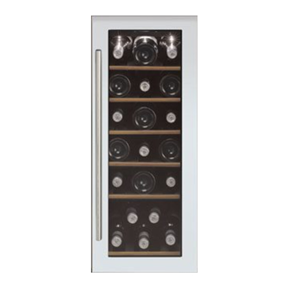
- Page 1 WI3118WH Caple 30cm 1 zone wine cabinet Caple 30cm 1 zone wine cabinet Technical information...
- Page 3 WI3118WH - Caple 30cm 1 zone wine cabinet Item Part Code Description Dry filter DG11-45 Power cord DG2-14 Compressor DG1-72 Water tank DG13-199 PCB board cover DG13-272-1 Transformer DG6-7 PCB board DG3-98-12 Cabinet DG26-133-1 Decorative nail DG13-268 Evaporator fixing nip...
- Page 4 WI3118WH - Caple 30cm 1 zone wine cabinet Item Part Code Description Fan fixing piece DG14-33 Air-circulating pipe DG12-58 Gasket M184-041 Handle DG22-3027 Top left hinge DG14-190-SL Lower left hinge DG14-212-BL Bottom grill DG22-3022 Bottom grill DG22-3055-1 Bottom grill bracket...
- Page 6 WI3118WH Caple Single zone wine cabinet Caple Single zone wine cabinet Service Manual...
- Page 7 SERVICE MANUAL (One temperature zone control wine coolar) JG series includes JG18 series, JG32B,JG45AJG50A,JG50A-1,JG50FA The content below shows different default might happen when the wine cooler is working, and also shows how to find the defaults and repair the defaults. Please find the corresponding default statement and find the repair information in the corresponding pages.
- Page 8 ▲ Unstable internal temperature problems……………………………………………….………( Page 12) ▲ Control system problems ○ Fault finding by the self-check mode…………………………………………………………………..(Page 12) ○ Sensor fault …………………………………………………………………………………………...(Page 12) ………………………………………………………………………………..(Page 14) ○ LED display fault ○ How to remove the electrical box …………………………………………………………………. (Page 14) ○...
- Page 9 △ Cooling system faults. ○ How to diagnose faults: It should take approximate 3 hours to reach the lowest setting temperature of 5℃ for an empty unit (assuming ambient temp of 32 degrees centigrade and continuous operation). If not, check the compressor, cooling fans, controller, and sensors. If all these are working normally, there is probably a cooling system’s fault.
- Page 10 the unit the compressor should automatically stop within - 2.5 deg centigrade of the set temperature and start with +2.5 deg centigrade of the set temperature within approx 3 hours (assuming an ambient temperature of 32℃and the unit is empty). ○...
- Page 11 ③. Drive up the shelves make it above the fixer 1 (Fig.3),then take it out according to the arrowhead Fdirection(Fig.4) Fig.3 Fig.4 2>. How to remove the air duct board(A).(in Fig.5 1~10 are the screws fixing the air duct board,in different types,the situations and quantity of them are different,A~D are the screws fixing the fan,no need to remove), Remove the fixing screws of air duct board (1,2,3,4,5,6,7,8,9,10), then pull out air duct board (A).
- Page 12 3>. For a View of the internal configuration after removal of the air duct board, see (Fig.6 & Fig.7) ○Diagram showing the front side soldered joints (There are two different types of evaporator:Finned and pipe evaporator,se (Fig.6& Fig.7) A. Capillary soldered joints B.
- Page 13 ○ Diagram showing the rear side solder joints. There are two different condensers: built-in (Fig.8) and outboard (Fig.9 & Fig.9.1) condenser ).See Dry filter process pipe soldered joint Dry filter soldered joint Capillary soldered joint Process pipe soldered joint Suction pipe soldered joint Discharge pipe soldered joint Condenser process pipe soldered joint Anti-Dew pipe soldered joint...
- Page 14 Fig.9.1 Outboard condenser ▲ High noise of wine cellar ○ compressor noise 1. The working of motor and piston motion will cause noise when compressor working. So if noise is steady and not exceeds 42 dB, it’s normal. If noise is not steady or very high, it’s compressor fault and it should be repaired or replaced.
- Page 15 a. Replacing the evaporator fan 1>.Remove the shelf holde fixing screws, and remove the shelves. See (Fig.1, Fig.2 ,Fig.3,Fig.4) 2>.Remove the air duct board. See(Fig.5) 3>.Remove the fan fixing screws (1,2,3,4) ,and replace the fan. See (Fig.10) b. Replacing the condenser fan (different model may have different fan position, but the procedure for replacement is the same) 1>.
- Page 16 1>. De-solder the capillary and re-solder in the correct position avoiding contact with the inside of the evaporator, (The depth should be within 15mm), then recharge the unit with refrigerant see (→7) 2>. If the capillary touches the inside of the cabinet or air duct board, you should adjust position of capillary and pack it with anti-vibration compound.
- Page 17 4>. Fix the wire in the correct position using the cable clip with screw (Fig.15) Fig.14 Fig.15 5>. If fan is foult ,please relace the whole fan. 6>.Note:the upper method only for the connector fixed under the evaporator.
- Page 18 ▲ Unstalbe temperatures inside the cabinet Unstable temperatures inside the cabinet is mostly due to a fault in the evaporator fan, you can check this by: When compressor works, the “RUN” indicator light should come on and the fan should spin, If fan does not spin check the fans electrical connections are faulty and repair them or if the fan is damaged replace the whole fan unit see (fig...
- Page 19 Strip the ends of the wires, cut of the connect of new sensor and strip the ends of wires about 5>. 12mm , re-connect them. Ensure this electrical joint is sealed against future water damage, and is electrically safe Fix the wire in the correct position using the cable clip with screw (Fig17&...
- Page 20 If the LED displays” E1” it indicates the inner sensor should be replaced see 2 >. (Fig.18 & Fig.19) If the LED displays” E2” it indicates the inner sensor should be replaced see 3 >. (Fig.18& Fig.19) For some older models with old computerized control panels,If the LED displays 37℃, 99F 4 >....
- Page 21 a. Remove the the shelf , ( Fig.19) b.Unplug all the connector, press the 4 studs(3) one by one. Updraw the control PCB board, and draw off the PCB board, , replace it with the same model’s PCB board. ( Fig.19) Fig.19 Fig.20 Diagram of the main...
- Page 22 a.Remove the two screw(1) that fixing the electrical box for power PCB ( Fig.21). the electrical box(C) for power PCB b.Remove the ( Fig.21). c. Unplug all the connector, press the 4 studs(4) one by one. Updraw the power PCB board(A), and draw off the PCB board, , replace it with the same model’s PCB board.
- Page 23 How to replace the LED light 2>. Remove the electrical box,Unplug the LED light connector, press the 4 studs one by one,take the LED light upward,replace it. ( Fig.24) Fig.24 ○ How to replace the decorative frame Remove the screw(1,2,3),pull the decorative frame according to the arrowhead that view K show,then remove (Fig.25) the screw(4,5,6) from the gap betoween decorative frame and cabinet,remove the decorative frame.
- Page 24 Fig.25...
Need help?
Do you have a question about the WI3118WH and is the answer not in the manual?
Questions and answers