Table of Contents
Advertisement
Quick Links
Advertisement
Table of Contents

Subscribe to Our Youtube Channel
Related Manuals for Major tech MT874


Summary of Contents for Major tech MT874
- Page 1 INSTRUCTION MANUAL MT874 600V AC/DC TRMS MULTIMETER...
-
Page 3: Table Of Contents
Contents Page no 1. Safety.................... 4 1.1. Safety Instructions..............4 1.2. Safety Symbols............... 4 1.3. Input Limits................5 1.4. Safety Category Ratings............5 1.5. Test Leads................5 2. Description..................6 2.1. Meter Description..............6 2.2. Symbols Used on LCD Display..........7 3. -
Page 4: Safety
1. Safety 1.1. Safety Instructions • This meter has been designed for safe use, but must be operated with caution. • The instructions listed below must be carefully followed for safe operation. 1. Never apply voltage or current to the meter that exceeds the specified maximum: 2. -
Page 5: Input Limits
1.3. Input Limits Voltage AC or DC 600 V AC/DC, 200Vrms on 200mV range Resistance, Continuity 250 Vrms for 15 sec max mA DC or mA AC 200mA 600V fast acting fuse A DC or A AC 10A 600V fast acting fuse (30 seconds max every 15 minutes) •... -
Page 6: Description
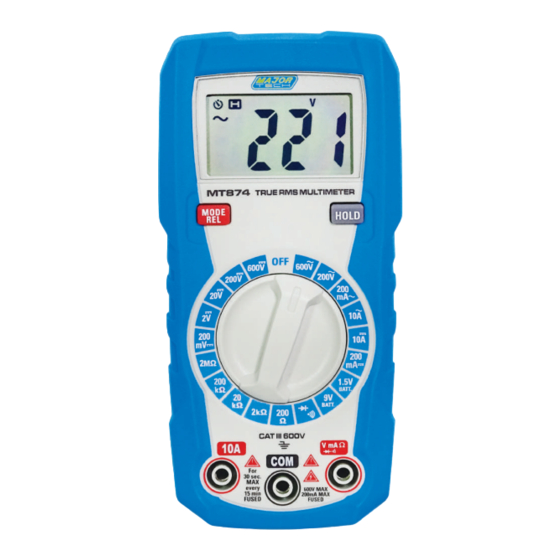
2. Description 2.1. Meter Description 1 - LCD Display 7 - COM Input Jack 2 - MODE/RELATIVE Button 8 - Lanyard Hole 3 - HOLD Button 9 - Test Lead Holders 4 - Function Switch 10 - Battery Cover Lock 5 - 10A Input Jack 11 - Tilt Stand 6 - Positive Input Jack... -
Page 7: Symbols Used On Lcd Display
2.2. Symbols Used on LCD Display 1 - Auto Power Off 7 - Alternating Current 2 - Display Hold 8 - Direct Current 3 - Relative 9 - Minus Sign 4 - Diode Test 10 - Battery Status 11 - Measurement Reading 5 - Continuity 6 - Units of Measure List... -
Page 8: Specifications
3. Specifications 3.1.Specifications Range Resolution Function Accuracy 200mV 0.1mV DC Voltage 0.001V ±(0.5% + 5 digits) 0.01V 0.1V 200V ±(0.8% + 5 digits) 600V ±(1.2% + 10 digits) 200V 0.1V AC Voltage 600V All AC voltage ranges are specified from 5% of range to 100% of range; AC voltage bandwidth: 50Hz to 1kHz (Sine), 50Hz to 60Hz (All wave). -
Page 9: General Specifications
3.2. General Specifications Insulation Class 2, Double insulation. Diode Test Test current of 1mA maximum, open circuit voltage 2V DC typical Continuity Check Audible signal will sound if the resistance is less than approximately 50Ω Battery Test current 9V (6mA); 1.5V (100mA) Input Impedance Approximately 10MΩ... -
Page 10: Battery Installation
4. Battery Installation WARNING: To avoid electric shock, disconnect the test leads from any source of voltage before removing the battery cover. 1. Disconnect the test leads from the meter. 2. Open the battery cover by loosening the screw using a Flat head screwdriver. -
Page 11: Operating Instructions
6. Operating Instructions WARNING: Risk of electrocution. High-voltage circuits, both AC and DC, are very dangerous and should be measured with great care. • Always turn the function switch to the OFF Position when the meter is not in use. •... -
Page 12: Ac Voltage Measurement
6.2. AC Voltage Measurement WARNING: Risk of Electrocution. The probe tips may not be long enough to contact the live parts inside some 240V outlets for appliances because the contacts are recessed deep in the outlets. As a result, the reading may show 0 volts when the outlet actually has voltage on it. -
Page 13: Dc Current Measurement
6.3. DC Current Measurement CAUTION: Do not make current measurements on the 10A scale for longer than 30 seconds. Exceeding 30 seconds may cause damage to the meter and/or the test leads. 1. Insert the black test lead banana plug into the COM Input Jack. 2. -
Page 14: Ac Current Measurement
6.4. AC Current Measurement CAUTION: Do not make current measurements on the 10A scale for longer than 30 seconds. Exceeding 30 seconds may cause damage to the meter and/or the test leads. 1. Insert the black test lead banana plug into the COM Input Jack. 2. -
Page 15: Resistance Measurement
6.5. Resistance Measurement WARNING: To avoid electric shock, disconnect power to the unit under test and discharge all capacitors before taking any resistance measurements. 1. Set the function switch to the highest Ω Position. 2. Insert the black test lead banana plug into the negative COM Input Jack; Insert the red test lead banana plug into the Positive Input Jack. -
Page 16: Continuity Check
6.6. Continuity Check WARNING: To avoid electric shock, never measure continuity on circuits or wires that have voltage on them. 1. Set the function switch to the Position. 2. Insert the black test lead banana plug into the negative COM Input Jack;... -
Page 17: Diode Test
6.7. Diode Test 1. Set the function switch to the Position. 2. Insert the black test lead banana plug into the negative COM Input Jack; Insert the red test lead banana plug into the Positive Input Jack. 3. Press the Mode/Rel Button until “ ”... -
Page 18: Battery Test
6.8. Battery Test 1. Insert the black test lead banana plug into the negative COM Input Jack; Insert the red test lead banana plug into the Positive Input Jack. 2. Select the 1.5V or 9V BAT Position using the function select switch. 3. -
Page 19: Replacing The Battery
7. Replacing The Battery WARNING: To avoid electric shock, disconnect the test leads from any source of voltage before removing the battery cover. 1. When the batteries become exhausted or drop below the operating voltage, “ ” will appear in the LCD display, the batteries should be replaced. - Page 20 MAJOR TECH (PTY) LTD www.major-tech.com www.majortech.com.au sales@major-tech.com info@majortech.com.au...
Need help?
Do you have a question about the MT874 and is the answer not in the manual?
Questions and answers