
Subscribe to Our Youtube Channel
Related Manuals for THORLABS PDB440A


Summary of Contents for THORLABS PDB440A
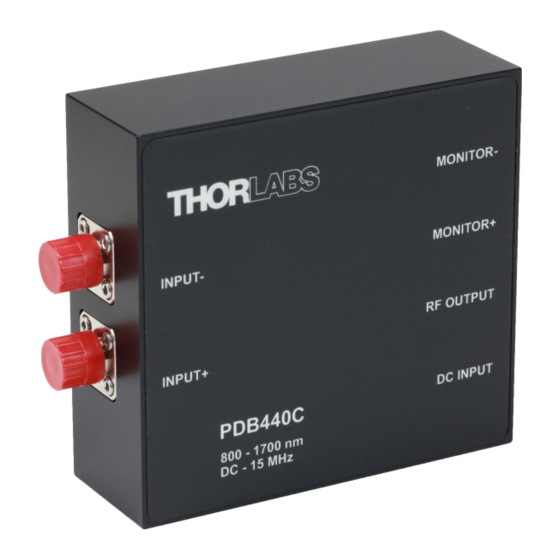
- Page 1 Balanced Amplified Photodetectors PDB440A, PDB440A-AC, PDB440C, PDB440C-AC, PDB450A, PDB450A-AC, PDB450C, PDB450C-AC Operation Manual 2019...
- Page 2 Version: Date: 08-Apr-2019 Item No.: M0009-510-1043 Copyright © 2019 Thorlabs...
-
Page 3: Table Of Contents
3.6 CMRR and Frequency Response 3.7 Recommendations 4 Maintenance and Service 5 Appendix 5.1 Technical Data 5.1.1 PDB440x Individual Technical Data 5.1.2 PDB450x Individual Technical Data 5.2 Dimensions 5.3 Certifications and Compliances 5.4 Warranty 5.5 Copyright and Exclusion of Reliability 5.6 Thorlabs Worldwide Contacts... -
Page 4: Foreword
Paragraphs preceded by this symbol explain hazards that could damage the instrument and the connected equipment or may cause loss of data. Note This manual also contains "NOTES" and "HINTS" written in this form. Please read this advice carefully! © 2019 Thorlabs... -
Page 5: General Information
If necessary, ask for replacement pack- aging. Refer servicing to qualified personnel! Only with written consent from Thorlabs may changes to single components be made or components not supplied by Thorlabs be used. 1.2 Ordering Codes and Accessories... -
Page 6: Getting Started
Note Prior to operation, please check, if the indicated line voltage range on the power supply matches with your local mains voltage! If you want use your own power supply, Thorlabs offers an appropriate power connector cable. Carefully unpack the unit and accessories. If any damage is noticed, do not use the unit ·... -
Page 7: Operating Instruction
3.1 Operating Principle Thorlabs product family of PDB440x and PDB450x detectors Balanced Amplified Photodetect- ors consist of two well-matched photodiodes and an ultra-low noise, high-speed transimped- ance amplifier that generates an output voltage (RF OUTPUT) proportional to the difference between the photo currents of the two photodiodes, i.e. -
Page 8: Optical Inputs
For free-space beam applications it is recommended to remove the FC adapter (receptacle) to have direct access to the photodiodes as shown below on a drawing of the PDB410C. This is identical to PDB440 and PDB450. Please be aware the INPUT+ and INPUT- are reversed in PDB440x versus PDB450x. © 2019 Thorlabs... - Page 9 In balanced mode the power difference between the optical inputs should be less than the CW Saturation Power. If necessary, use external neutral density filters or attenuators to reduce the input light level. Attention The optical damage threshold is 20 mW. Exceeding this value will permanently damage the photodiodes! © 2019 Thorlabs...
-
Page 10: Electrical Outputs
PDB440x and PDB450x detectors 3.3 Electrical Outputs The Thorlabs PDB440x and PDB450x detectors has three SMA output connectors: · MONITOR + · MONITOR - · RF OUTPUT RF OUTPUT delivers an output voltage proportional to the difference between the photo cur-... -
Page 11: Mounting
DC coupled RF Output signals when modulating the input signal with a mechanical chopper at a fre- quency of 500 Hz. Note : The input signal for AC coupling was in- creased by factor 2 to allow direct waveform com- parison. © 2019 Thorlabs... -
Page 12: Cmrr And Frequency Response
OUTPUT must be considered when calculating the CMRR - it is the difference between the RF OUTPUT signal at a given frequency and the measured common mode or balanced output sig- nal - at the same frequency. Typical measurement curves can be found in the individual tech- nical data. © 2019 Thorlabs... -
Page 13: Recommendations
· Another critical point can be electrostatic coupling of electrical noise associated with ground loops. In most cases an electrically isolated post (see Thorlabs parts TRE or TRE/M) will suppress electrical noise coupling. Always try to identify the electrical noise sources and in- crease the distance to the PDB440x and PDB450x detectors Balanced Detector. -
Page 14: Maintenance And Service
Do not soak the unit in water or use solvent based cleaners. When cleaning the windows of the photodetectors, please remember that is a sensitive optical device. Gently blow off any debris using compressed air and wipe gently with an optic tissue wetted with isopropanol or alcohol. © 2019 Thorlabs... -
Page 15: Appendix
50 W loads. Monitor outputs conversion gain is 10 V/mW, given at the detectors peak responsivity and high impedance load. Typical frequency response curves are measured using the setup described in section "CMRR and Frequency Response" © 2019 Thorlabs... -
Page 16: Technical Data
Operating Temperature Range Storage Temperature Range -40 to 70 °C Weight 0.35 kg (w/o power supply) ) Values are given for high impedance load. For a 50 W load, values are to be divided by 2. ) non-condensing © 2019 Thorlabs... - Page 17 5 Appendix Typical Detector responsivity curves Typical Si Detector responsivity (PDB440A, PDB450A) Typical InGaAs Detector responsivity (PDA440C, PDB450C) Typical Monitor Output Frequency Response PDB440 and PDB450 Series Monitor Output Frequency Response © 2019 Thorlabs...
-
Page 18: Pdb440X Individual Technical Data
) Values are given at peak responsivity of the detector, for high impedance load. For a 50 W load, values are to be divided by 2. PDB440A: Typical RF OUTPUT Frequency Response PDB440A: Typical RF OUTPUT Frequency Response © 2019 Thorlabs... - Page 19 5 Appendix PDB440A: RF OUTPUT Spectral Noise PDB440A: RF OUTPUT Spectral Noise PDB440C: Typical RF OUTPUT Frequency Response PDB440C: Typical RF OUTPUT Frequency Response © 2019 Thorlabs...
- Page 20 PDB440x and PDB450x detectors PDB440C: RF OUTPUT Spectral Noise PDB440C: RF OUTPUT Spectral Noise © 2019 Thorlabs...
-
Page 21: Pdb450X Individual Technical Data
) Values are given at peak responsivity of the detector, for high impedance load. For a 50 W load, values are to be divided by 2. PDB450A: Typical RF OUTPUT Frequency Response PDB450A: Typical RF OUTPUT Frequency Response at different gain settings © 2019 Thorlabs... - Page 22 PDB440x and PDB450x detectors PDB450A: RF OUTPUT Spectral Noise PDB450A: RF OUTPUT Spectral Noise at different gain settings PDB450C: Typical RF OUTPUT Frequency Response PDB450C: Typical RF OUTPUT Frequency Response at different gain settings © 2019 Thorlabs...
- Page 23 5 Appendix PDB450C: RF OUTPUT Spectral Noise PDB450C: RF OUTPUT Spectral Noise at different gain settings © 2019 Thorlabs...
-
Page 24: Dimensions
PDB440x and PDB450x detectors 5.2 Dimensions Mechanical Drawing PDB440 © 2019 Thorlabs... - Page 25 5 Appendix Mechanical Drawing PDB450 © 2019 Thorlabs...
-
Page 26: Certifications And Compliances
PDB440x and PDB450x detectors 5.3 Certifications and Compliances © 2019 Thorlabs... -
Page 27: Warranty
Thorlabs warrants material and production of the PDB440x and PDB450x detectors for a period of 24 months starting with the date of shipment. During this warranty period Thorlabs will see to defaults by repair or by exchange if these are entitled to warranty. -
Page 28: Thorlabs Worldwide Contacts
Contact Thorlabs for more information. Waste treat- ment is your own responsibility. “End of life” units must be returned to Thorlabs or handed to a company specializing in waste recovery. Do not dispose of the unit in a litter bin or at a public waste disposal site. - Page 29 www.thorlabs.com...
Need help?
Do you have a question about the PDB440A and is the answer not in the manual?
Questions and answers