Table of Contents
Advertisement
Quick Links
Advertisement
Table of Contents

Related Manuals for THORLABS PDA10DT


Summary of Contents for THORLABS PDA10DT
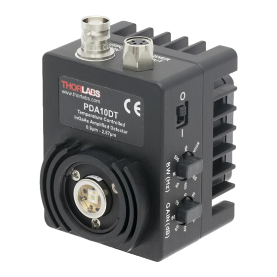
- Page 1 PDA10DT(-EC) Amplified InGaAs Detector User Guide...
-
Page 2: Table Of Contents
4.5. Light-to-Voltage Conversion .......... 5 Chapter 5 Maintenance ..............6 Chapter 6 Troubleshooting ............... 6 Chapter 7 Specifications ..............7 Chapter 8 Drawings ................. 13 Chapter 9 Regulatory ............... 14 Chapter 10 Certificate of Conformance ........... 15 Chapter 11 Thorlabs Worldwide Contacts........16... -
Page 3: Chapter 1 Warning Symbol Definitions
Amplified InGaAs Detector Chapter 1: Warning Symbol Definitions Chapter 1 Warning Symbol Definitions Below is a list of warning symbols you may encounter in this manual or on your device. Symbol Description Direct Current Alternating Current Both Direct and Alternating Current Earth Ground Terminal Protective Conductor Terminal Frame or chassis Terminal... -
Page 4: Chapter 2 Description
The SM1-threaded mount can be easily integrated into our cage and lens tube systems. The PDA10DT(-EC) has two 8-32 (M4) tapped holes for mounting the detector on a Ø1/2" optical post in one of two perpendicular directions. The detector includes a 100 - 240 V, 47 - 63 Hz power supply. -
Page 5: Chapter 3 Setup
Attach a 50 Ω BNC cable to the output of the PDA. When running cable lengths longer than 12", we recommend terminating the opposite end of the coax with a 50 Ω resistor (Thorlabs’ T4119 BNC in-line terminator) for maximum performance. Connect the remaining end to a measurement device such as an oscilloscope or high-speed DAQ card. - Page 6 Amplified InGaAs Detector Chapter 3: Setup Turn on the PDA10DT using the power switch located on the top side of the detector. Install any desired filters, optics, adapters, or fiber adapters to the input aperture. CAUTION The PDA10DT was designed to allow maximum accessibility to the photodetector by having the front surface of the diode flush with the outside of the PDA housing.
-
Page 7: Chapter 4 Operation
> 5 kΩ) and 5 V for 50 Ω loads. Adjust the gain so that the measured signal level out of the PDA10DT is below 10 V (5 V for a 50 Ω load) to avoid saturation. If necessary, use external neutral density filters to reduce the input light level. The BNC output signal is buffered with an amplifier capable of driving 50 Ω... -
Page 8: Bandwidth Filter Adjustment
The PDA10DT also includes an adjustable low-pass filter with settings from 500 Hz to 1 MHz in 8 steps. This filter allows the user to optimize the PDA10DT to operate at the lowest amount of high-frequency optical and electrical noise. The filter is adjusted by rotating the filter control knob, located on the side of the unit. -
Page 9: Chapter 5 Maintenance
Chapter 5: Maintenance Chapter 5 Maintenance There are no serviceable parts in the PDA10DT detector or power supply. The housing may be cleaned by wiping with a soft damp cloth. The window of the detector should only be cleaned using isopropyl alcohol and optical grade wipes. -
Page 10: Chapter 7 Specifications
0 V (20 dB - 70 dB) All measurements performed with a 50 Ω load unless stated otherwise. The PDA10DT has a 50 Ω series terminator resistor (i.e., in series with amplifier output). This forms a voltage divider with any load impedance (e.g., 50 Ω... - Page 11 Amplified InGaAs Detector Chapter 7: Specifications General Specifications Detector Extended InGaAs PIN Active Area 0.8 mm (Ø1.0 mm) Surface Depth 0.08" (2.0 mm) Output Weight (Detector/Power Supply) 0.42 lbs / 0.82 lbs (191 g / 372 g) Power Supply 30 W 100 - 240 VAC, 47 –...
- Page 12 Amplified InGaAs Detector Chapter 7: Specifications Figure 3 PDA10DT Gain Bandwidth Figure 4 PDA10DT Filter Bandwidth Rev M, September 7, 2021 Page 9...
- Page 13 Amplified InGaAs Detector Chapter 7: Specifications Figure 5 Noise at 70 dB Gain amd 500 Hz Bandwidth Page 10 13129-D02...
- Page 14 Amplified InGaAs Detector Chapter 7: Specifications Figure 6 Noise at 0 and 70 dB Gain and 1 MHz Bandwidth Rev M, September 7, 2021 Page 11...
- Page 15 Amplified InGaAs Detector Chapter 7: Specifications Figure 7 TEC Current vs. Temperature Figure 8 Photosensitivity at -10 °C and 25 °C Page 12 13129-D02...
-
Page 16: Chapter 8 Drawings
Amplified InGaAs Detector Chapter 8: Drawings Chapter 8 Drawings Rev M, September 7, 2021 Page 13... -
Page 17: Chapter 9 Regulatory
Waste Treatment is Your Own Responsibility If you do not return an "end of life" unit to Thorlabs, you must hand it to a company specialized in waste recovery. Do not dispose of the unit in a litter bin or at a public waste disposal site. -
Page 18: Chapter 10 Certificate Of Conformance
Amplified InGaAs Detector Chapter 10: Certificate of Conformance Chapter 10 Certificate of Conformance Rev M, September 7, 2021 Page 15... -
Page 19: Chapter 11 Thorlabs Worldwide Contacts
Amplified InGaAs Detector Chapter 11: Thorlabs Worldwide Contacts Chapter 11 Thorlabs Worldwide Contacts For technical support or sales inquiries, please visit us at www.thorlabs.com/contact for our most up-to-date contact information. USA, Canada, and South America UK and Ireland Thorlabs, Inc. - Page 20 www.thorlabs.com...
Need help?
Do you have a question about the PDA10DT and is the answer not in the manual?
Questions and answers