Table of Contents
Advertisement
Quick Links
Advertisement
Table of Contents

Related Manuals for THORLABS PDA10D


Summary of Contents for THORLABS PDA10D
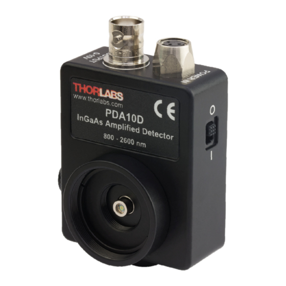
- Page 1 PDA10D(-EC) Extended InGaAs Amplified Detector User Guide...
-
Page 2: Table Of Contents
6.1. Response Curve.............. 9 6.2. Mechanical Drawing ............ 10 Chapter 7 Certificate of Conformance ........... 11 Chapter 8 Regulatory ............... 12 8.1. Waste Treatment is Your Own Responsibility .... 12 8.2. Ecological Background .......... 12 Chapter 9 Thorlabs Worldwide Contacts........13 ... -
Page 3: Chapter 1 Warning Symbol Definitions
InGaAs Amplified Detector Chapter 1: Warning Symbol Definitions Chapter 1 Warning Symbol Definitions Below is a list of warning symbols you may encounter in this manual or on your device. Symbol Description Direct Current Alternating Current Both Direct and Alternating Current Earth Ground Terminal Protective Conductor Terminal Frame or chassis Terminal... -
Page 4: Chapter 2 Description
Chapter 2: Description Chapter 2 Description The PDA10D(-EC) is an amplified, InGaAs detector designed for detection of light ranging from 800 to 2600 nm. A buffered output drives 50 Ω load impedances up to 5 V. The PDA10D(-EC) housing includes a removable threaded coupler (SM1T1) and retaining ring (SM1RR) that is compatible with any number of Thorlabs 1”... -
Page 5: Chapter 3 Setup
Attach a 50 Ω coax cable (i.e. RG-58U) to the output of the PDA. When running cable lengths longer than 12" we recommend terminating the opposite end of the coax with a 50 Ω resistor (Thorlabs p/n T4119) for maximum performance. Connect the remaining end to a measurement device such as an oscilloscope or high speed DAQ card. -
Page 6: Chapter 4 Operation
Chapter 4 Operation 4.1. Theory of Operation Thorlabs PDA series are ideal for measuring both pulsed and CW light sources. The PDA10D(-EC) includes a reverse-biased PIN photo diode, mated to a fixed gain transimpedance amplifier, and packaged in a rugged housing. -
Page 7: Dark Current
InGaAs Amplified Detector Chapter 4: Operation 4.3. Dark Current Dark current is leakage current which flows when a bias voltage is applied to a photodiode. The PDA with Transimpedance Amplifier does control the dark current flowing out. Looking at the figure above, it can be noted that Point B is held at ground and the amplifier will try to hold point A to “Virtual Ground”. - Page 8 > 5 kΩ) and 5 volts for 50 Ω loads. Adjust the gain so that the measured Load signal level out of the PDA10D(-EC) is below 10 volts (5 volts with a 50 Ω load) to avoid saturation. For low terminating resistors, <5 kΩ or 1% error, an additional factor needs to be considered.
-
Page 9: Chapter 5 Troubleshooting
InGaAs Amplified Detector Chapter 5: Troubleshooting Chapter 5 Troubleshooting Problem Suggested Solutions Verify that the power is switched on and all connections are secure. Verify the proper terminating resistor is installed if using a Voltage measurement device. There is no signal response. Verify that the optical signal wavelength is within the specified wavelength range. -
Page 10: Chapter 6 Specifications
Input Power 100 – 200 VAC (50 to 60 Hz) 220 – 240 VAC (50 to 60 Hz) Although the power supply is rated for 31 W the PDA10D actual usage is <5 W over the full operating range. Page 8... -
Page 11: Response Curve
InGaAs Amplified Detector Chapter 6: Specifications 6.1. Response Curve PDA10D(-EC) Responsivity Wavelength (µm) Rev G, December 19, 2017 Page 9... -
Page 12: Mechanical Drawing
InGaAs Amplified Detector Chapter 6: Specifications 6.2. Mechanical Drawing Visit the web for a more detailed mechanical drawing. Page 10 13127-D01... -
Page 13: Chapter 7 Certificate Of Conformance
InGaAs Amplified Detector Chapter 7: Certificate of Conformance Chapter 7 Certificate of Conformance Rev G, December 19, 2017 Page 11... -
Page 14: Chapter 8 Regulatory
8.1. Waste Treatment is Your Own Responsibility If you do not return an “end of life” unit to Thorlabs, you must hand it to a company specialized in waste recovery. Do not dispose of the unit in a litter bin or at a public waste disposal site. -
Page 15: Chapter 9 Thorlabs Worldwide Contacts
InGaAs Amplified Detector Chapter 9: Thorlabs Worldwide Contacts Chapter 9 Thorlabs Worldwide Contacts For technical support or sales inquiries, please visit us at www.thorlabs.com/contact for our most up-to-date contact information. USA, Canada, and South America UK and Ireland Thorlabs, Inc. - Page 16 www.thorlabs.com...
Need help?
Do you have a question about the PDA10D and is the answer not in the manual?
Questions and answers